User Guide
Page 8
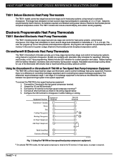
... automatic changeover. Electronic Programmable Heat Pump Thermostats T8011 Standard Electronic Heat Pump Thermostats The T8011 models provide two-stage heat and one -stage cool in the wiring diagram below. 5. Battery backup, with electric heat or fossil fuel while providing optimum comfort. HEAT PUMP THERMOSTAT CROSS REFERENCE/SELECTION GUIDE T8511 Deluxe Electronic Heat Pump Thermostats The T8511 models control two-stage heat and one -stage cool control for use of...
... automatic changeover. Electronic Programmable Heat Pump Thermostats T8011 Standard Electronic Heat Pump Thermostats The T8011 models provide two-stage heat and one -stage cool in the wiring diagram below. 5. Battery backup, with electric heat or fossil fuel while providing optimum comfort. HEAT PUMP THERMOSTAT CROSS REFERENCE/SELECTION GUIDE T8511 Deluxe Electronic Heat Pump Thermostats The T8511 models control two-stage heat and one -stage cool control for use of...
User Guide
Page 9
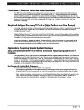
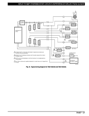
... T8611G and T8611M Y terminal. When the system switch is energized on the R8222B Switching Relay. second stage heat anticipation is fixed; Honeywell does not recommend this requirement, a separate switching relay must be turned off in the Installer Set-up...control brings the room temperature to three-stage heat and two-stage cool control for stage 1 heat and stage 1 cool. See the following wiring diagrams for heat pumps that provide changeover in order to be energized on a call for heat, the thermostat Y terminal activates the first stage of heating. * The O terminal is connected...
... T8611G and T8611M Y terminal. When the system switch is energized on the R8222B Switching Relay. second stage heat anticipation is fixed; Honeywell does not recommend this requirement, a separate switching relay must be turned off in the Installer Set-up...control brings the room temperature to three-stage heat and two-stage cool control for stage 1 heat and stage 1 cool. See the following wiring diagrams for heat pumps that provide changeover in order to be energized on a call for heat, the thermostat Y terminal activates the first stage of heating. * The O terminal is connected...
User Guide
Page 11
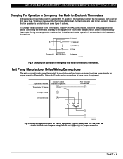
... wiring diagram shown below. Connecting the thermostat and relay to specific types of heat pump equipment require a separate relay for some types of equipment. HT. Relay wiring connections for proper operation. 70-6627 • 9 R (Power) E C (Common) E (EM. Heat Pump Manufacturer Relay Wiring Connections The wiring connections for proper operation. Existing Control Equipment Function Terminal Designation Transformer Common C 1st Stage Cooling...
... wiring diagram shown below. Connecting the thermostat and relay to specific types of heat pump equipment require a separate relay for some types of equipment. HT. Relay wiring connections for proper operation. 70-6627 • 9 R (Power) E C (Common) E (EM. Heat Pump Manufacturer Relay Wiring Connections The wiring connections for proper operation. Existing Control Equipment Function Terminal Designation Transformer Common C 1st Stage Cooling...

User Guide
Page 15
... and indicates the malfunction by being drawn in the system switching (EX: Q674F with EM. HEAT PUMP THERMOSTAT CROSS REFERENCE/SELECTION GUIDE Understanding Circuits To understand wiring diagrams, it is named (EX: H1 anticipator, C1 anticipator). C1-Stage 1 Cooling. All T874 Multistage Thermostats use mercury switches. KEY TO HOOKUP SYMBOLS TRANSFORMER (24 VAC SECONDARY) RELAY OR CONTACTOR...
... and indicates the malfunction by being drawn in the system switching (EX: Q674F with EM. HEAT PUMP THERMOSTAT CROSS REFERENCE/SELECTION GUIDE Understanding Circuits To understand wiring diagrams, it is named (EX: H1 anticipator, C1 anticipator). C1-Stage 1 Cooling. All T874 Multistage Thermostats use mercury switches. KEY TO HOOKUP SYMBOLS TRANSFORMER (24 VAC SECONDARY) RELAY OR CONTACTOR...

User Guide
Page 17
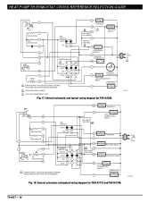
... EM. RELAY SYSTEM MONITOR X LACO Y HEAT CHANGEOVER VALVE COMPRESSOR CONTACTOR O COOL CHANGEOVER VALVE CHP M6060A Fig. 16. HT. HT. PROVIDE DISCONNECT MEANS AND OVERLOAD PROTECTION AS REQUIRED. 2 NO AUTO FAN IN EMERGENCY HEAT. HT. Internal schematic and typical wiring diagram for T841A1308. 70-6627 • 15 W2 AUX. HEAT PUMP THERMOSTAT CROSS REFERENCE/SELECTION GUIDE Typical System...
... EM. RELAY SYSTEM MONITOR X LACO Y HEAT CHANGEOVER VALVE COMPRESSOR CONTACTOR O COOL CHANGEOVER VALVE CHP M6060A Fig. 16. HT. HT. PROVIDE DISCONNECT MEANS AND OVERLOAD PROTECTION AS REQUIRED. 2 NO AUTO FAN IN EMERGENCY HEAT. HT. Internal schematic and typical wiring diagram for T841A1308. 70-6627 • 15 W2 AUX. HEAT PUMP THERMOSTAT CROSS REFERENCE/SELECTION GUIDE Typical System...
User Guide
Page 18
... THERMOSTAT X2 T OUTDOOR O THERMISTOR COOL CHANGEOVER RELAY COMPRESSOR CONTACTOR Y 2 FIELD REMOVABLE JUMPER. 3 AUTO FAN IN EMERGENCY HEAT. HEAT RELAY 8 11 12 FALL H2 10 SYSTEM SWITCH 3 EM. Internal schematic and typical wiring diagram for T841A1712 and T841A1738. W3 O EM. HEAT LED (GREEN) B EM. HEAT RELAY AUX. HEAT RELAY B HEAT CHANGEOVER RELAY COMPRESSOR CONTACTOR Y Fig. 18. HEAT OFF 1 RESET 4 COOL 1 POWER SUPPLY. HEAT LED...
... THERMOSTAT X2 T OUTDOOR O THERMISTOR COOL CHANGEOVER RELAY COMPRESSOR CONTACTOR Y 2 FIELD REMOVABLE JUMPER. 3 AUTO FAN IN EMERGENCY HEAT. HEAT RELAY 8 11 12 FALL H2 10 SYSTEM SWITCH 3 EM. Internal schematic and typical wiring diagram for T841A1712 and T841A1738. W3 O EM. HEAT LED (GREEN) B EM. HEAT RELAY AUX. HEAT RELAY B HEAT CHANGEOVER RELAY COMPRESSOR CONTACTOR Y Fig. 18. HEAT OFF 1 RESET 4 COOL 1 POWER SUPPLY. HEAT LED...
User Guide
Page 19
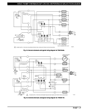
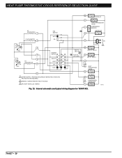
... VALVE M6068A Fig. 19. Internal schematic and typical wiring diagram for T841B1000. HEAT PUMP THERMOSTAT CROSS REFERENCE/SELECTION GUIDE H1/C1 ANTICIPATOR H1 C1 FALL FAN SWITCH AUTO ON W1 HEAT RELAY 1 W2 HEAT RELAY 2 B HEAT CHANGEOVER VALVE G FAN RELAY H2 ANTICIPATOR H2 FALL SYSTEM SWITCH HEAT OFF COOL 1 POWER SUPPLY. AUTO OFF C815A OUTDOOR THERMISTOR T FAN RELAY G CHANGEOVER...
... VALVE M6068A Fig. 19. Internal schematic and typical wiring diagram for T841B1000. HEAT PUMP THERMOSTAT CROSS REFERENCE/SELECTION GUIDE H1/C1 ANTICIPATOR H1 C1 FALL FAN SWITCH AUTO ON W1 HEAT RELAY 1 W2 HEAT RELAY 2 B HEAT CHANGEOVER VALVE G FAN RELAY H2 ANTICIPATOR H2 FALL SYSTEM SWITCH HEAT OFF COOL 1 POWER SUPPLY. AUTO OFF C815A OUTDOOR THERMISTOR T FAN RELAY G CHANGEOVER...
User Guide
Page 20
...RED) X AUX. HT. Internal schematic and typical wiring diagram for Y594G1633. H1 RISE 1 CHANGEOVER (HEAT) FALL 2 H1 ANTICIPATOR 3 FALL 4 FAN SWITCH AUTO ON W3 G FAN RELAY R W3 RELAY L2 1 L1 (HOT) H2 5 H2 ANTICIPATOR FALL 6 CHANGEOVER 8 (COOL) 9 RISE 10 C1 ANTICIPATOR C1 11 SYSTEM .... HT. HEAT RELAY W2 L1 (HOT) L2 1 Y 1 POWER SUPPLY. LED (RED) X COOL CHANGEOVER VALVE O B W1 RELAY W1 HEAT CHANGEOVER VALVE 2 COMPRESSOR CONTACTOR Y1 1 POWER SUPPLY. REMOVE JUMPER WHEN W1 RELAY IS USED. HT. HT. RELAY AUX. HEAT PUMP THERMOSTAT CROSS REFERENCE/...
...RED) X AUX. HT. Internal schematic and typical wiring diagram for Y594G1633. H1 RISE 1 CHANGEOVER (HEAT) FALL 2 H1 ANTICIPATOR 3 FALL 4 FAN SWITCH AUTO ON W3 G FAN RELAY R W3 RELAY L2 1 L1 (HOT) H2 5 H2 ANTICIPATOR FALL 6 CHANGEOVER 8 (COOL) 9 RISE 10 C1 ANTICIPATOR C1 11 SYSTEM .... HT. HEAT RELAY W2 L1 (HOT) L2 1 Y 1 POWER SUPPLY. LED (RED) X COOL CHANGEOVER VALVE O B W1 RELAY W1 HEAT CHANGEOVER VALVE 2 COMPRESSOR CONTACTOR Y1 1 POWER SUPPLY. REMOVE JUMPER WHEN W1 RELAY IS USED. HT. HT. RELAY AUX. HEAT PUMP THERMOSTAT CROSS REFERENCE/...
User Guide
Page 21
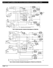
... AND C1 ANTICIPATOR 3 H1 FALL FALL C1 4 H2 ANTICIPATOR H2 6 FAN SWITCH AUTO ON SYSTEM SWITCH EM. Internal schematic and typical wiring diagram for Y594R1797. HEAT RELAY W2 FAN RELAY G COOL CHANGEOVER VALVE O COOL E COMPRESSOR EM. HEAT PUMP THERMOSTAT CROSS REFERENCE/SELECTION GUIDE 1 2 H1 C1 FALL 3 4 H2 FALL 5 6 11 AUTO ON FAN SWITCH SYSTEM SWITCH EM. AUX...
... AND C1 ANTICIPATOR 3 H1 FALL FALL C1 4 H2 ANTICIPATOR H2 6 FAN SWITCH AUTO ON SYSTEM SWITCH EM. Internal schematic and typical wiring diagram for Y594R1797. HEAT RELAY W2 FAN RELAY G COOL CHANGEOVER VALVE O COOL E COMPRESSOR EM. HEAT PUMP THERMOSTAT CROSS REFERENCE/SELECTION GUIDE 1 2 H1 C1 FALL 3 4 H2 FALL 5 6 11 AUTO ON FAN SWITCH SYSTEM SWITCH EM. AUX...
User Guide
Page 22
... W1 RELAY IS USED. 3 FACTORY-INSTALLED JUMPER. LED (GRN) W2 AUX. O COOL CHANGEOVER VALVE L COMPRESSOR MONITOR FAN RELAY G R EM. HT. Internal schematic and typical wiring diagram for Y594R1425. 70-6627 • 20 HT. HT. LED (RED) AUX. HT. RELAY E EM. HEAT PUMP THERMOSTAT CROSS REFERENCE/SELECTION GUIDE W3 W3 RELAY H1 ANTICIPATOR 1 C ANTICIPATOR 2 FAN SWITCH...
... W1 RELAY IS USED. 3 FACTORY-INSTALLED JUMPER. LED (GRN) W2 AUX. O COOL CHANGEOVER VALVE L COMPRESSOR MONITOR FAN RELAY G R EM. HT. Internal schematic and typical wiring diagram for Y594R1425. 70-6627 • 20 HT. HT. LED (RED) AUX. HT. RELAY E EM. HEAT PUMP THERMOSTAT CROSS REFERENCE/SELECTION GUIDE W3 W3 RELAY H1 ANTICIPATOR 1 C ANTICIPATOR 2 FAN SWITCH...
User Guide
Page 23
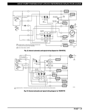
... W2 AUX. HEAT OFF AUTO COOL C. B HEAT CHANGEOVER VALVE HIGH LIMIT HEAT 1 1 POWER SUPPLY. RELAY E EM. L1 (HOT) L2 1 70-6627 • 21 HT. HT. COOL CHANGEOVER VALVE O COOL C. HT. O. RELAY FAN RELAY G SYSTEM SWITCH EM. O. PROVIDE DISCONNECT MEANS AND OVERLOAD PROTECTION AS REQUIRED. 2 DENOTES THERMOSTAT TO SUBBASE INTERCONNECT. Typical wiring diagram for T8611G1004 and T8611G1103. HEAT PUMP THERMOSTAT CROSS REFERENCE...
... W2 AUX. HEAT OFF AUTO COOL C. B HEAT CHANGEOVER VALVE HIGH LIMIT HEAT 1 1 POWER SUPPLY. RELAY E EM. L1 (HOT) L2 1 70-6627 • 21 HT. HT. COOL CHANGEOVER VALVE O COOL C. HT. O. RELAY FAN RELAY G SYSTEM SWITCH EM. O. PROVIDE DISCONNECT MEANS AND OVERLOAD PROTECTION AS REQUIRED. 2 DENOTES THERMOSTAT TO SUBBASE INTERCONNECT. Typical wiring diagram for T8611G1004 and T8611G1103. HEAT PUMP THERMOSTAT CROSS REFERENCE...

User Guide
Page 24
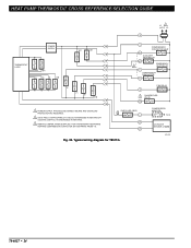
HT. Typical wiring diagram for T8611M7008. HT. RELAY W3 HEAT 3 STAGE 2 RELAY W2 HEAT 2 EM. O. M2656 70-6627 • 22 HEAT OFF AUTO COOL COOL 1 FAN RELAY G COOL CHANGEOVER C. VALVE O C. HT. PROVIDE DISCONNECT MEANS AND OVERLOAD PROTECTION AS ... SEPARATE SENSOR FOR REMOTE TEMPERATURE SENSING. 6 RECOMMENDED INTERCONNECT CABLE: 18-GAUGE THERMOSTAT CABLE, 200 FT. (61 M) MAXIMUM LENGTH. LED (GREEN) L MONITOR AUX. HEAT CHANGEOVER VALVE B STAGE 1 COMPRESSOR CONTACTOR Y STAGE 2 COMPRESSOR CONTACTOR Y2 COOL 2 X1 2 CHECK LED (YELLOW) X2 L1 (HOT) L2 1 ...
HT. Typical wiring diagram for T8611M7008. HT. RELAY W3 HEAT 3 STAGE 2 RELAY W2 HEAT 2 EM. O. M2656 70-6627 • 22 HEAT OFF AUTO COOL COOL 1 FAN RELAY G COOL CHANGEOVER C. VALVE O C. HT. PROVIDE DISCONNECT MEANS AND OVERLOAD PROTECTION AS ... SEPARATE SENSOR FOR REMOTE TEMPERATURE SENSING. 6 RECOMMENDED INTERCONNECT CABLE: 18-GAUGE THERMOSTAT CABLE, 200 FT. (61 M) MAXIMUM LENGTH. LED (GREEN) L MONITOR AUX. HEAT CHANGEOVER VALVE B STAGE 1 COMPRESSOR CONTACTOR Y STAGE 2 COMPRESSOR CONTACTOR Y2 COOL 2 X1 2 CHECK LED (YELLOW) X2 L1 (HOT) L2 1 ...
User Guide
Page 25
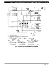
... SYSTEM WITH ISOLATED STAGE 1 HEATING AND COOLING CONNECTIONS. 3 DENOTES THERMOSTAT TO SUBBASE INTERCONNECT. DEFROST CONTROL M6019A Fig. 28. M11333 Fig. 29. HT. LED (GREEN) L MONITOR W2 AUX. Typical wiring diagram for T8611R1000. L1 (HOT) L2 1 THERMISTOR SENSOR THERMOSTAT LOGIC STAGE 2 RELAY STAGE 1 RELAY SYSTEM SWITCH EM. Typical wiring diagram for T8011R and T8411R. 70-6627 • 23 HEAT PUMP THERMOSTAT CROSS REFERENCE/SELECTION...
... SYSTEM WITH ISOLATED STAGE 1 HEATING AND COOLING CONNECTIONS. 3 DENOTES THERMOSTAT TO SUBBASE INTERCONNECT. DEFROST CONTROL M6019A Fig. 28. M11333 Fig. 29. HT. LED (GREEN) L MONITOR W2 AUX. Typical wiring diagram for T8611R1000. L1 (HOT) L2 1 THERMISTOR SENSOR THERMOSTAT LOGIC STAGE 2 RELAY STAGE 1 RELAY SYSTEM SWITCH EM. Typical wiring diagram for T8011R and T8411R. 70-6627 • 23 HEAT PUMP THERMOSTAT CROSS REFERENCE/SELECTION...
User Guide
Page 26
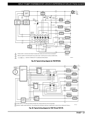
... FROM Y1). COMPRESSOR MONITOR TO R OUTDOOR SENSOR C7089B M13281 70-6627 • 24 HEAT PUMP THERMOSTAT CROSS REFERENCE/SELECTION GUIDE L1 1 (HOT) L2 R THERMOSTAT LOGIC POWER SUPPLY W2 W1 E Y1 G O/B W2 W1 C COMPRESSOR CONTACTOR HEAT W1 AUXILIARY HEAT RELAY W2 3 EMERGENCY HEAT RELAY E COMPRESSOR CONTACTOR Y1 E Y1 G O/B FAN RELAY G 2 CHANGEOVER VALVE O/B 1 POWER SUPPLY. Typical wiring diagram for T8511G.
... FROM Y1). COMPRESSOR MONITOR TO R OUTDOOR SENSOR C7089B M13281 70-6627 • 24 HEAT PUMP THERMOSTAT CROSS REFERENCE/SELECTION GUIDE L1 1 (HOT) L2 R THERMOSTAT LOGIC POWER SUPPLY W2 W1 E Y1 G O/B W2 W1 C COMPRESSOR CONTACTOR HEAT W1 AUXILIARY HEAT RELAY W2 3 EMERGENCY HEAT RELAY E COMPRESSOR CONTACTOR Y1 E Y1 G O/B FAN RELAY G 2 CHANGEOVER VALVE O/B 1 POWER SUPPLY. Typical wiring diagram for T8511G.
User Guide
Page 27
... (RED) X1 X2 CHECK LED (RED) L OT 2 OT Fig. 31. Typical wiring diagram for T8611G2002 and T8611G2028. FACTORY DEFAULT IS O-ENERGIZED IN COOL MODE. 4 FACTORY-INSTALLED JUMPER; HEAT PUMP THERMOSTAT CROSS REFERENCE/SELECTION GUIDE L1 1 (HOT) L2 R POWER SUPPLY THERMOSTAT LOGIC W2 W1 E C COMPRESSOR CONTACTOR HEAT W1 AUXILIARY HEAT RELAY W2 4 EMERGENCY HEAT RELAY E COMPRESSOR CONTACTOR Y1 Y O/B G 1 POWER SUPPLY.
... (RED) X1 X2 CHECK LED (RED) L OT 2 OT Fig. 31. Typical wiring diagram for T8611G2002 and T8611G2028. FACTORY DEFAULT IS O-ENERGIZED IN COOL MODE. 4 FACTORY-INSTALLED JUMPER; HEAT PUMP THERMOSTAT CROSS REFERENCE/SELECTION GUIDE L1 1 (HOT) L2 R POWER SUPPLY THERMOSTAT LOGIC W2 W1 E C COMPRESSOR CONTACTOR HEAT W1 AUXILIARY HEAT RELAY W2 4 EMERGENCY HEAT RELAY E COMPRESSOR CONTACTOR Y1 Y O/B G 1 POWER SUPPLY.
User Guide
Page 35
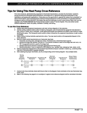
...and wire the Honeywell electromechanical, Chronotherm III, or electronic heat pump thermostats in this reference. 2. To use the corresponding control hookup diagram. Note the unique control requirements your customer's needs; O terminal cool or B terminal heat is listed, followed by Honeywell, even if thermostat ...cool. - Best of automatic heat/cool changeover and to a Chronotherm® IV thermostat that puts the heat pump to work to match up for first stage heat. - This one comfort center controls temperature, indoor air quality, ventilation, humidity, and zoning. Identify heat...
...and wire the Honeywell electromechanical, Chronotherm III, or electronic heat pump thermostats in this reference. 2. To use the corresponding control hookup diagram. Note the unique control requirements your customer's needs; O terminal cool or B terminal heat is listed, followed by Honeywell, even if thermostat ...cool. - Best of automatic heat/cool changeover and to a Chronotherm® IV thermostat that puts the heat pump to work to match up for first stage heat. - This one comfort center controls temperature, indoor air quality, ventilation, humidity, and zoning. Identify heat...
User Guide
Page 45
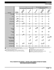
...;² Lº - 2nd Stage Cool Y2 Y2 Y2 Y2 Y2 Y2 ³ Terminal must be connected to the transformer common. · For auxiliary heat LED indication, jumper X2 to E. » Relay required (R8222B1067 typically) for wiring diagram. ¿ Optional LED indication activated with completed circuit on Q674. M13148 TYPICAL THERMOSTATS AND SUBBASES - HONEYWELL MODEL NUMBER (CUSTOMER PART...
...;² Lº - 2nd Stage Cool Y2 Y2 Y2 Y2 Y2 Y2 ³ Terminal must be connected to the transformer common. · For auxiliary heat LED indication, jumper X2 to E. » Relay required (R8222B1067 typically) for wiring diagram. ¿ Optional LED indication activated with completed circuit on Q674. M13148 TYPICAL THERMOSTATS AND SUBBASES - HONEYWELL MODEL NUMBER (CUSTOMER PART...
User Guide
Page 53
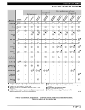
...wiring diagram. ´ Terminal must be provided as contactors, sequencers, or relays. ¶ Do not remove factory-installed jumper. º Field-installed X2 to X (C) jumper. ¾ When W2 is not used, configure W2 cycle rate to obtain replacements for these thermostats. M13204 TYPICAL THERMOSTATS AND SUBBASES - L - Heat Loads ² LED Indication X (3) 2nd Stage...180; BLCK X (2) Power RED R (1) Compressor Y Y (6) 1st Stage - - Heat (4) W2 W2 Fan G G C/O Valve - Y2 - Heat Aux. B Heat C/O Valve V O Cool (5) X X C R R R or Y Y1 Y1 Y ¶...
...wiring diagram. ´ Terminal must be provided as contactors, sequencers, or relays. ¶ Do not remove factory-installed jumper. º Field-installed X2 to X (C) jumper. ¾ When W2 is not used, configure W2 cycle rate to obtain replacements for these thermostats. M13204 TYPICAL THERMOSTATS AND SUBBASES - L - Heat Loads ² LED Indication X (3) 2nd Stage...180; BLCK X (2) Power RED R (1) Compressor Y Y (6) 1st Stage - - Heat (4) W2 W2 Fan G G C/O Valve - Y2 - Heat Aux. B Heat C/O Valve V O Cool (5) X X C R R R or Y Y1 Y1 Y ¶...

User Guide
Page 81
... page 78. See page 78 for wiring diagram. º Configure O/B (select models) in Installer Setup. ¾ LED is energized when terminal is powered. µ L terminal is powered continuously when thermostat is in AUTO position, equipment will operate in Em. position. LED Indication - - ² X1 X2 - Heat E E E E E E Thermistor A - - - - - 1st Stage Heat - Heat System Monitor/ L System Defrost G O B · X2...
... page 78. See page 78 for wiring diagram. º Configure O/B (select models) in Installer Setup. ¾ LED is energized when terminal is powered. µ L terminal is powered continuously when thermostat is in AUTO position, equipment will operate in Em. position. LED Indication - - ² X1 X2 - Heat E E E E E E Thermistor A - - - - - 1st Stage Heat - Heat System Monitor/ L System Defrost G O B · X2...
User Guide
Page 121
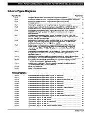
... section has reset shunt relay and malfunction light indicator is desired on thermostat 11 Relay wiring connections for PC8900 in heat pump applications requiring separate Y1 and W1 terminals with a cooling changeover 12 Key to hookup symbols...13 NEMA Class 2 transformer band 14 Wiring Diagrams Fig. 16 Fig. 17 Fig. 18 Fig. 19 Fig. 20 Fig...
... section has reset shunt relay and malfunction light indicator is desired on thermostat 11 Relay wiring connections for PC8900 in heat pump applications requiring separate Y1 and W1 terminals with a cooling changeover 12 Key to hookup symbols...13 NEMA Class 2 transformer band 14 Wiring Diagrams Fig. 16 Fig. 17 Fig. 18 Fig. 19 Fig. 20 Fig...


