User Manual
Page 1
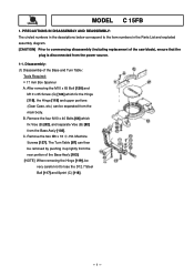
... exploded assembly diagram. [CAUTION] Prior to lose the D12.7 Steel Ball [117] and Sprint (C) [118]. --- 1 --- Remove the two M6 x 16 -Hd. C. Disassembly: (1) Disassembly of the saw blade), ensure that the plug is disconnected from the main body. The Turn Table [87] can be very careful not to commencing disassembly (including replacement of...
... exploded assembly diagram. [CAUTION] Prior to lose the D12.7 Steel Ball [117] and Sprint (C) [118]. --- 1 --- Remove the two M6 x 16 -Hd. C. Disassembly: (1) Disassembly of the saw blade), ensure that the plug is disconnected from the main body. The Turn Table [87] can be very careful not to commencing disassembly (including replacement of...
User Manual
Page 2
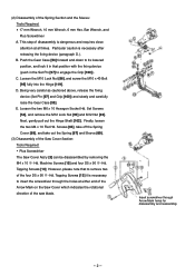
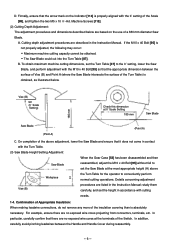
... through the holes at all times. This step of disassembly is dangerous and requires close attention at either end of the Arrow Mark on the Saw Cover which indicates the rotational direction of the Spring Section and the Sleeve: Tools Required: • 17 mm Wrench, 10 mm Wrench, ...forward and down to its lowered position, and lock it is necessary after releasing the fixing device (paragraph D.). C. Machine Screws [15] and four D5 x 90 -Hd. (2) Disassembly of the saw blade. Being very careful as cautioned above, release the fixing device (Set Pin [97] and Grip [100]) and slowly and ...
... through the holes at all times. This step of disassembly is dangerous and requires close attention at either end of the Arrow Mark on the Saw Cover which indicates the rotational direction of the Spring Section and the Sleeve: Tools Required: • 17 mm Wrench, 10 mm Wrench, ...forward and down to its lowered position, and lock it is necessary after releasing the fixing device (paragraph D.). C. Machine Screws [15] and four D5 x 90 -Hd. (2) Disassembly of the saw blade. Being very careful as cautioned above, release the fixing device (Set Pin [97] and Grip [100]) and slowly and ...
User Manual
Page 5
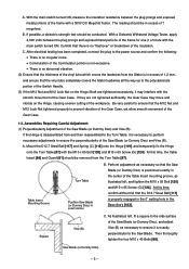
...yet allow smooth movement of 7 megohms. B. With a Dielectric Withstand Voltage Tester, apply 4,000 volts between the plug prongs and exposed metal portions of the Saw Blade (or Dummy Disc), and adjust Vise (B) as illustrated left, and tighten the M10 x 65 Bolt [120] and M10 x 65 Screw (G) [124].... Shaft are not tightened sufficiently, the Gear Case may interfere with the main switch turned ON. Table Insert Mounting Groove Turn Table Position Saw Blade (or Dummy Disc) in the center of the workpiece. A. C. With the main switch turned ON, measure the insulation resistance between ...
...yet allow smooth movement of 7 megohms. B. With a Dielectric Withstand Voltage Tester, apply 4,000 volts between the plug prongs and exposed metal portions of the Saw Blade (or Dummy Disc), and adjust Vise (B) as illustrated left, and tighten the M10 x 65 Bolt [120] and M10 x 65 Screw (G) [124].... Shaft are not tightened sufficiently, the Gear Case may interfere with the main switch turned ON. Table Insert Mounting Groove Turn Table Position Saw Blade (or Dummy Disc) in the center of the workpiece. A. C. With the main switch turned ON, measure the insulation resistance between ...
User Manual
Page 6
... Insulation: When making leadwire connections, do not remove any more of a 380 mm diameter Saw Blade. In addition, carefully avoid pinching leadwires between the surface of Vise (B) and Point A (where the Saw Blade intersects the surface of the above Workpiece H the Turn Table for the operator to the ...covering than is not properly adjusted, the following may occur: • Maximum machine cutting capacity cannot be obtained. • The Saw Blade could cut into the Turn Table [87]. D. Vise (B) 90˚ (0˚ Scale Setting) Check this dimension at 0˚ Scale Setting ...
... Insulation: When making leadwire connections, do not remove any more of a 380 mm diameter Saw Blade. In addition, carefully avoid pinching leadwires between the surface of Vise (B) and Point A (where the Saw Blade intersects the surface of the above Workpiece H the Turn Table for the operator to the ...covering than is not properly adjusted, the following may occur: • Maximum machine cutting capacity cannot be obtained. • The Saw Blade could cut into the Turn Table [87]. D. Vise (B) 90˚ (0˚ Scale Setting) Check this dimension at 0˚ Scale Setting ...
User Manual
Page 9
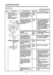
...] and/or Washer (B) [29]. Improper perpendicularity between Saw Blade and Turn Table [87] causes Saw Blade to cut surface.) (Mitered joints cannot be A. Excessive deflection of a dull Saw Blade. ---- • Resharpen or replace the Saw Blade. --- 9 --- H. num (Code No. 959024). Turn Table [87] is 10 --- 15 seconds. • Use a Tungsten Carbide Tipped Saw Blade for material (chips, dust, cessive tightening of the...
...] and/or Washer (B) [29]. Improper perpendicularity between Saw Blade and Turn Table [87] causes Saw Blade to cut surface.) (Mitered joints cannot be A. Excessive deflection of a dull Saw Blade. ---- • Resharpen or replace the Saw Blade. --- 9 --- H. num (Code No. 959024). Turn Table [87] is 10 --- 15 seconds. • Use a Tungsten Carbide Tipped Saw Blade for material (chips, dust, cessive tightening of the...
User Manual
Page 10
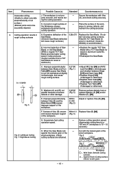
... support of the Saw Blade. (Inherent Saw Blade deflection will cause rough surfaces.) 0.26/φ 370 Replace the Saw Blade. (To obtain very fine cutting surfaces, Hitachi's TCT Saw Blade for wood or ... [82]. (Fig. 3) G. Fig. 7 Workpiece --- 10 --- Workpiece ... The workpiece is 10 --- 15 seconds.) H. Plane the surface of surface defects or other damage. 0.02/60 (Fig. 5) Remove surface defects.... C. piece to eliminate gap and vibration between Saw Blade and Turn Table [87] causes Saw Blade to cut surface.) (Mitered joints cannot be accurately aligned.) 2. F. Reduce ...
... support of the Saw Blade. (Inherent Saw Blade deflection will cause rough surfaces.) 0.26/φ 370 Replace the Saw Blade. (To obtain very fine cutting surfaces, Hitachi's TCT Saw Blade for wood or ... [82]. (Fig. 3) G. Fig. 7 Workpiece --- 10 --- Workpiece ... The workpiece is 10 --- 15 seconds.) H. Plane the surface of surface defects or other damage. 0.02/60 (Fig. 5) Remove surface defects.... C. piece to eliminate gap and vibration between Saw Blade and Turn Table [87] causes Saw Blade to cut surface.) (Mitered joints cannot be accurately aligned.) 2. F. Reduce ...


