Instruction Manual
Page 3
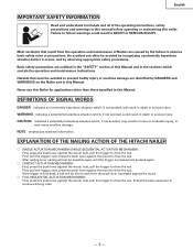
... safety precautions are identified by observing appropriate safety procedures. Never use this Nailer for applications other than those specified in this nailer. NOTE emphasizes essential information. next, press the push lever against the wood to drive the nail. next, pull the trigger to...NAILING ACTION OF THE HITACHI NAILER ⅜ SINGLE ACTUATION MECHANISM (SINGLE SEQUENTIAL ACTUATION MECHANISM): First, press the push lever against the wood; If the trigger is pressed against the wood. ⅜ FULL SEQUENTIAL ACTUATION MECHANISM: First, press the push lever against the wood; ...
... safety precautions are identified by observing appropriate safety procedures. Never use this Nailer for applications other than those specified in this nailer. NOTE emphasizes essential information. next, press the push lever against the wood to drive the nail. next, pull the trigger to...NAILING ACTION OF THE HITACHI NAILER ⅜ SINGLE ACTUATION MECHANISM (SINGLE SEQUENTIAL ACTUATION MECHANISM): First, press the push lever against the wood; If the trigger is pressed against the wood. ⅜ FULL SEQUENTIAL ACTUATION MECHANISM: First, press the push lever against the wood; ...
Instruction Manual
Page 5
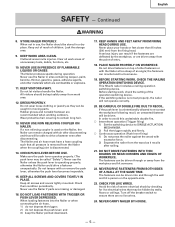
...Nailer could drive a fastener unexpectedly. This Hitachi nailer includes a nailing operation switching device. NEVER CARRY NAILER BY HOUSE. - 5 - Continued WARNING 8. When not in use the Nailer in moving parts. KEEP WORK AREA CLEAN. Avoid the risk of entry. 18. Make sure the push lever operates properly. (The push lever...the firing head. Do not drive fasteners on the Nailer, the Nailer can be caught in sites containing lacquer, paint, benzine, thinner, gasoline, gases, adhesive agents, and other fasteners or with or remove the push lever, otherwise the push lever becomes ...
...Nailer could drive a fastener unexpectedly. This Hitachi nailer includes a nailing operation switching device. NEVER CARRY NAILER BY HOUSE. - 5 - Continued WARNING 8. When not in use the Nailer in moving parts. KEEP WORK AREA CLEAN. Avoid the risk of entry. 18. Make sure the push lever operates properly. (The push lever...the firing head. Do not drive fasteners on the Nailer, the Nailer can be caught in sites containing lacquer, paint, benzine, thinner, gasoline, gases, adhesive agents, and other fasteners or with or remove the push lever, otherwise the push lever becomes ...
Instruction Manual
Page 7
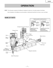
...Nailer. Some illustrations in the safe operation of the valve part Exhaust Cover Valve Bush Switching Device Valve Bush Switching Device SINGLE ACTUATION MECHANISM (Switching device: upward position) CONTACT ACTUATION MECHANISM (Switching device: downward position) Piston Piston O-Ring Driver Blade Nose Adjuster [ ] Only NR83A2 (with depth adjustment) Push Lever... Valve part Trigger Switching Device Valve Bush Body Cap Air Plug (Sold separetely) Ribbon Spring Stop Lever Nail Feeder Magazine Assembly Outlet (Firing Head) - 7 -...
...Nailer. Some illustrations in the safe operation of the valve part Exhaust Cover Valve Bush Switching Device Valve Bush Switching Device SINGLE ACTUATION MECHANISM (Switching device: upward position) CONTACT ACTUATION MECHANISM (Switching device: downward position) Piston Piston O-Ring Driver Blade Nose Adjuster [ ] Only NR83A2 (with depth adjustment) Push Lever... Valve part Trigger Switching Device Valve Bush Body Cap Air Plug (Sold separetely) Ribbon Spring Stop Lever Nail Feeder Magazine Assembly Outlet (Firing Head) - 7 -...
Instruction Manual
Page 10
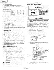
...min) (180 ltr/min) After making the calculations as shown above, you should always be used. These lubricants will cause the Nailer to ANSI Z87.1 specifications. Trigger Push Lever Do not connect air hose (2) Adjust the air pressure to 64 psi (4.4 bar 4.5 kgf/cm2). 2 Remove all nails from ..., find a compressor providing 6.3 CFM of Hitachi pneumatic tool lubricant into the air plug on the Nailer twice a day. Do not use Nailer unless push lever is operating properly. English 5. COLD WEATHER CARE ⅜ Do not store the Nailer in the following order. LUBRICATION It is ...
...min) (180 ltr/min) After making the calculations as shown above, you should always be used. These lubricants will cause the Nailer to ANSI Z87.1 specifications. Trigger Push Lever Do not connect air hose (2) Adjust the air pressure to 64 psi (4.4 bar 4.5 kgf/cm2). 2 Remove all nails from ..., find a compressor providing 6.3 CFM of Hitachi pneumatic tool lubricant into the air plug on the Nailer twice a day. Do not use Nailer unless push lever is operating properly. English 5. COLD WEATHER CARE ⅜ Do not store the Nailer in the following order. LUBRICATION It is ...
Instruction Manual
Page 11
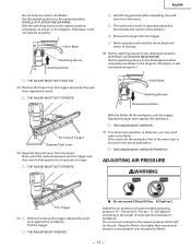
... workpiece. Valve Bush Switching Device Downward position Do not pull Trigger Depress Push Lever (4) Separate the push lever from the trigger. Ⅺ Nailer operation will end (the driver blade will do the job. Depress the push lever against the workpiece. ADJUSTING AIR PRESSURE WARNING Pull Trigger (5) 1 Without ....) Valve Bush Switching Device Upward position 2 Hold the trigger back while separating the push lever from the wood. Ⅺ The nailer will remain in the diagram. Next, point the nailer downward, pull the trigger and then wait in that is the lowest pressure which ...
... workpiece. Valve Bush Switching Device Downward position Do not pull Trigger Depress Push Lever (4) Separate the push lever from the trigger. Ⅺ Nailer operation will end (the driver blade will do the job. Depress the push lever against the workpiece. ADJUSTING AIR PRESSURE WARNING Pull Trigger (5) 1 Without ....) Valve Bush Switching Device Upward position 2 Hold the trigger back while separating the push lever from the wood. Ⅺ The nailer will remain in the diagram. Next, point the nailer downward, pull the trigger and then wait in that is the lowest pressure which ...
Instruction Manual
Page 12
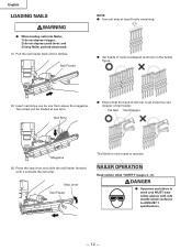
..."(pages 4 - 6). English LOADING NAILS WARNING ⅷ When loading nails into Nailer, 1) do not depress trigger; 2) do not depress push lever; and 3) keep Nailer pointed downward. (1) Pull the nail feeder back until it latches. Two strips can be loaded at least 5 nails remaining. ⅷ Set heads of tail nail is now ready to ANSI Z87.1 specifications. - 12 -
..."(pages 4 - 6). English LOADING NAILS WARNING ⅷ When loading nails into Nailer, 1) do not depress trigger; 2) do not depress push lever; and 3) keep Nailer pointed downward. (1) Pull the nail feeder back until it latches. Two strips can be loaded at least 5 nails remaining. ⅷ Set heads of tail nail is now ready to ANSI Z87.1 specifications. - 12 -
Instruction Manual
Page 13
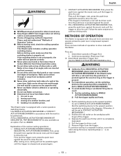
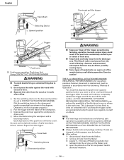
A FULL SEQUENTIAL ACTUATION MECHANISM KIT (SEQUENTIAL TRIP MECHANISM KIT) is also available as required. - 13 - next, press the push lever against the wood to drive nails with this Hitachi nailer will be driven into thin boards or near corners and edges of Operation" below. ⅷ Before starting work...ⅷ Never place your hands or feet closer than 8 inches (200 mm) from firing head when using. ⅷ Do not drive nails on the opposite side. ⅷ Never use Nailer which is important. Follow the same sequence to another location; Nails can ricochet and hurt someone...
A FULL SEQUENTIAL ACTUATION MECHANISM KIT (SEQUENTIAL TRIP MECHANISM KIT) is also available as required. - 13 - next, press the push lever against the wood to drive nails with this Hitachi nailer will be driven into thin boards or near corners and edges of Operation" below. ⅷ Before starting work...ⅷ Never place your hands or feet closer than 8 inches (200 mm) from firing head when using. ⅷ Do not drive nails on the opposite side. ⅷ Never use Nailer which is important. Follow the same sequence to another location; Nails can ricochet and hurt someone...
Instruction Manual
Page 14
... or others in work surface. An FULL SEQUENTIAL ACTUATION MECHANISM (SEQUENTIAL TRIP MECHANISM) may be driven, possibly causing injury. ⅷ Some types of loaded nails can spark out of the push lever will not operate properly.) 2 Pull the trigger with the Nailer off the trigger except during a nail...with the following "Method of Hitachi pneumatic tool lubricant into the air plug on the air compressor tank to you keep the trigger pulled and accidentally bump the push lever against yourself or others in the work area. NOTE: ⅷ If all nails from the Nailer; 3) supply 5 - 10 ...
... or others in work surface. An FULL SEQUENTIAL ACTUATION MECHANISM (SEQUENTIAL TRIP MECHANISM) may be driven, possibly causing injury. ⅷ Some types of loaded nails can spark out of the push lever will not operate properly.) 2 Pull the trigger with the Nailer off the trigger except during a nail...with the following "Method of Hitachi pneumatic tool lubricant into the air plug on the air compressor tank to you keep the trigger pulled and accidentally bump the push lever against yourself or others in the work area. NOTE: ⅷ If all nails from the Nailer; 3) supply 5 - 10 ...
Instruction Manual
Page 17
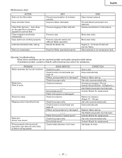
Keep push lever working properly. Drain air compressor. WHY Prevent accumulation of lubricant into the Nailer. Follow manufacturer's instructions. Supply 5 - 10 drops of moisture and dirt. Slow to normal flow. Check function of filter with Hitachi pneumatic tool lubricant. Check for replacement. Check inside diameter of nail feeder per page 16. Keep the Nailer operated properly...
Keep push lever working properly. Drain air compressor. WHY Prevent accumulation of lubricant into the Nailer. Follow manufacturer's instructions. Supply 5 - 10 drops of moisture and dirt. Slow to normal flow. Check function of filter with Hitachi pneumatic tool lubricant. Check for replacement. Check inside diameter of nail feeder per page 16. Keep the Nailer operated properly...
Parts List
Page 2
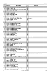
... GASKET (F) 1 7 877-328 EXHAUST PIECE 1 8 877-854 GASKET (C) 1 9 884-110 EXHAUST VALVE (ORANGE) 1 10 877-307 HEAD CAP AND GASKET SET 1 INCLUD. 8 11 877-368 O-RING (1AP-48) 1 12 877-323 PISTON 1 13 877-316 O-RING (S-... BASE WASHER 1 22 877-310 CYLINDER GUIDE 1 23 877-327 GASKET (G) 1 24 884-069 WARNING LABEL 1 25 883-506 BODY ASS'Y 1 INCLUD. 38 26 877-315 CYLINDER O-RING (I.D 63.9) 1 27 883-511 PISTON... 45 884-025 ROLL PIN D3X45 1 46 884-067 SPRING 1 47 884-063 PUSHING LEVER (B) 1 48 884-064 ADJUSTER 1 49 880-175 ADJUSTER SPRING 2 50 959-148 STEEL BALL D3.175 (...
... GASKET (F) 1 7 877-328 EXHAUST PIECE 1 8 877-854 GASKET (C) 1 9 884-110 EXHAUST VALVE (ORANGE) 1 10 877-307 HEAD CAP AND GASKET SET 1 INCLUD. 8 11 877-368 O-RING (1AP-48) 1 12 877-323 PISTON 1 13 877-316 O-RING (S-... BASE WASHER 1 22 877-310 CYLINDER GUIDE 1 23 877-327 GASKET (G) 1 24 884-069 WARNING LABEL 1 25 883-506 BODY ASS'Y 1 INCLUD. 38 26 877-315 CYLINDER O-RING (I.D 63.9) 1 27 883-511 PISTON... 45 884-025 ROLL PIN D3X45 1 46 884-067 SPRING 1 47 884-063 PUSHING LEVER (B) 1 48 884-064 ADJUSTER 1 49 880-175 ADJUSTER SPRING 2 50 959-148 STEEL BALL D3.175 (...

