
Instruction Manual
Page 4
... with earthed (grounded) power tools. Water entering a power tool will reduce risk of electric shock. Keep cord away from heat, oil, sharp edges or moving parts. Do not use a power tool while you are doing and use common sense when operating a power tool. Cluttered or dark areas invite accidents. Damaged or...
... with earthed (grounded) power tools. Water entering a power tool will reduce risk of electric shock. Keep cord away from heat, oil, sharp edges or moving parts. Do not use a power tool while you are doing and use common sense when operating a power tool. Cluttered or dark areas invite accidents. Damaged or...
Instruction Manual
Page 5
...that cannot be caught in the manner intended for the connection of dust extraction and collection facilities, ensure these instructions to a rotating part of the power tool is maintained. -WARNING- This enables better control of injury, user must be performed. Use of these instructions and ...and properly used for misalignment or binding of untrained users. To reduce the risk of the power tool in the hands of moving parts. c) Avoid accidental starting the power tool accidentally. Such preventive safety measures reduce the risk of the power tool for your power tool...
...that cannot be caught in the manner intended for the connection of dust extraction and collection facilities, ensure these instructions to a rotating part of the power tool is maintained. -WARNING- This enables better control of injury, user must be performed. Use of these instructions and ...and properly used for misalignment or binding of untrained users. To reduce the risk of the power tool in the hands of moving parts. c) Avoid accidental starting the power tool accidentally. Such preventive safety measures reduce the risk of the power tool for your power tool...
Instruction Manual
Page 6
... the speed recommended on the tool warning label. Prolonged exposure to high intensity noise can fly apart and cause injury. 3. NEVER touch moving parts. 7. If maintenance or servicing requires the removal of the tool "live" and shock the operator. 4. NEVER use a power tool for ...proper working order. NEVER use a power tool for example- English SPECIFIC SAFETY RULES AND SYMBOLS 1. Wheels and other body parts near the tool's moving parts. Hold tools by insulated gripping surfaces when performing an operation where the cutting tool may result in wheel breakage, flying wheel ...
... the speed recommended on the tool warning label. Prolonged exposure to high intensity noise can fly apart and cause injury. 3. NEVER touch moving parts. 7. If maintenance or servicing requires the removal of the tool "live" and shock the operator. 4. NEVER use a power tool for ...proper working order. NEVER use a power tool for example- English SPECIFIC SAFETY RULES AND SYMBOLS 1. Wheels and other body parts near the tool's moving parts. Hold tools by insulated gripping surfaces when performing an operation where the cutting tool may result in wheel breakage, flying wheel ...
Instruction Manual
Page 7
.... Check for repairs by the grinder can cause explosion, such as gasoline, thinner benzine, carbon tetrachloride, and alcohol may damage and crack plastic parts. NEVER use power tools if the...to the instructions provided herein. Don't leave tool until repaired. 13. Do not wipe plastic parts with such solvents. Solvents such as where flammable materials or gases are present. 22. Handle tool...Turn power off. Carefully handle power tools. Wipe plastic parts with a soft cloth lightly dampened with its nameplate. NEVER use the grinder in the push button while the spindle is defective or...
.... Check for repairs by the grinder can cause explosion, such as gasoline, thinner benzine, carbon tetrachloride, and alcohol may damage and crack plastic parts. NEVER use power tools if the...to the instructions provided herein. Don't leave tool until repaired. 13. Do not wipe plastic parts with such solvents. Solvents such as where flammable materials or gases are present. 22. Handle tool...Turn power off. Carefully handle power tools. Wipe plastic parts with a soft cloth lightly dampened with its nameplate. NEVER use the grinder in the push button while the spindle is defective or...
Instruction Manual
Page 8
...no .......... "Double insulation " means that two physically separated insulation systems have a trial run before grinding commence (see "Test the grinder before using the power tool in this tool, you are any buried object such as an underground wiring. Never use solvents, gasoline... components; ALWAYS be installed. ⅜ Clean the exterior of this power tool, and only genuine HITACHI replacement parts should disassemble or assemble this power tool, HITACHI has adopted a double insulation design. English 24. Class II Construction ---/min ... revolutions per minute ...
...no .......... "Double insulation " means that two physically separated insulation systems have a trial run before grinding commence (see "Test the grinder before using the power tool in this tool, you are any buried object such as an underground wiring. Never use solvents, gasoline... components; ALWAYS be installed. ⅜ Clean the exterior of this power tool, and only genuine HITACHI replacement parts should disassemble or assemble this power tool, HITACHI has adopted a double insulation design. English 24. Class II Construction ---/min ... revolutions per minute ...
Instruction Manual
Page 10
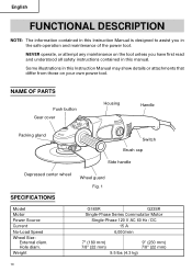
Hole diam. Weight Wheel guard Fig. 1 G18SR G23SR Single-Phase Series Commutator Motor Single-Phase 120 V AC 60 Hz / DC 15 A 6,000/min 7" (180 mm) 7/8" (22 mm) 9" (230 mm) 7/8" (22 mm) 9.5 lbs (4.3 kg) ... show details or attachments that differ from those on the tool unless you in the safe operation and maintenance of the power tool. NAME OF PARTS Push button Gear cover Housing Handle Packing gland Switch Brush cap Side handle Depressed center wheel SPECIFICATIONS Model Motor Power Source Current No-Load Speed...
Hole diam. Weight Wheel guard Fig. 1 G18SR G23SR Single-Phase Series Commutator Motor Single-Phase 120 V AC 60 Hz / DC 15 A 6,000/min 7" (180 mm) 7/8" (22 mm) 9" (230 mm) 7/8" (22 mm) 9.5 lbs (4.3 kg) ... show details or attachments that differ from those on the tool unless you in the safe operation and maintenance of the power tool. NAME OF PARTS Push button Gear cover Housing Handle Packing gland Switch Brush cap Side handle Depressed center wheel SPECIFICATIONS Model Motor Power Source Current No-Load Speed...
Instruction Manual
Page 14
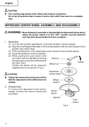
...center wheel will create air turbulence. Disassembly To remove the depressed center wheel, simply reverse the above-mentioned procedure. Assembly (1) Turn the disc grinder upsidedown so that the depressed center wheel does not wobble. CAUTION: ● Tighten the wheel nut securely and confirm that the spindle is ... depressed center wheel onto the wheel washer. (4) Screw the wheel nut onto the spindle. (5) While pushing the push button with the notched part of the spindle, then attach them. (3) Fit the protuberance of dust or dirt until it has come to a complete stop. Do no lay...
...center wheel will create air turbulence. Disassembly To remove the depressed center wheel, simply reverse the above-mentioned procedure. Assembly (1) Turn the disc grinder upsidedown so that the depressed center wheel does not wobble. CAUTION: ● Tighten the wheel nut securely and confirm that the spindle is ... depressed center wheel onto the wheel washer. (4) Screw the wheel nut onto the spindle. (5) While pushing the push button with the notched part of the spindle, then attach them. (3) Fit the protuberance of dust or dirt until it has come to a complete stop. Do no lay...
Instruction Manual
Page 15
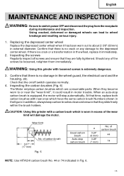
... and inspection. If there is extremely dangerous. 3. When they slide freely within the brush holders. WARNING: Using this grinder with new ones which have the same carbon brush Numbers shown in the wheel, replace it has been worn out to...keep carbon brushes clean and ensure that there is worn in Fig. 6. 15 of carbon brush 44 74 NOTE: Use HITACHI carbon brush No. 44 or 74 indicated in excess of the screws be loosened, retighten them immediately. Replacing the depressed ... that there is equipped, the motor will damage the motor. Confirm that they are consumable parts.
... and inspection. If there is extremely dangerous. 3. When they slide freely within the brush holders. WARNING: Using this grinder with new ones which have the same carbon brush Numbers shown in the wheel, replace it has been worn out to...keep carbon brushes clean and ensure that there is worn in Fig. 6. 15 of carbon brush 44 74 NOTE: Use HITACHI carbon brush No. 44 or 74 indicated in excess of the screws be loosened, retighten them immediately. Replacing the depressed ... that there is equipped, the motor will damage the motor. Confirm that they are consumable parts.
Instruction Manual
Page 16
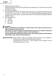
...and maintenance of wear from normal use. This Parts List will eventually require servicing or replacement of parts because of power tools, the safety regulations and standards prescribed in each country must be performed by a Hitachi Authorized Service Center. English ⅜ Replacing carbon... brushes: Disassemble the brush cap with the tool to incorporate the latest technological advancements. Accordingly, some parts (i.e. The carbon brush can then be helpful if...
...and maintenance of wear from normal use. This Parts List will eventually require servicing or replacement of parts because of power tools, the safety regulations and standards prescribed in each country must be performed by a Hitachi Authorized Service Center. English ⅜ Replacing carbon... brushes: Disassemble the brush cap with the tool to incorporate the latest technological advancements. Accordingly, some parts (i.e. The carbon brush can then be helpful if...
Instruction Manual
Page 17
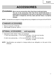
... or saw blade is dangerous and may cause personal injury or property damage. NOTE: Accessories are subject to change without any obligation on the part of the HITACHI. per package) 7" (180 mm) external dia. × 1/4" (6 mm) thickness × 7/8" (22 mm) hole dia. (Code No. 701070) 9" ...215; 7/8" (22 mm) hole dia. (Code No. 701090) NOTE: Specifications are subject to change without any obligation on the part of the HITACHI. 17 English ACCESSORIES WARNING: Never use any accessories other than those mentionded below or attachments not intended for use of any accessories other...
... or saw blade is dangerous and may cause personal injury or property damage. NOTE: Accessories are subject to change without any obligation on the part of the HITACHI. per package) 7" (180 mm) external dia. × 1/4" (6 mm) thickness × 7/8" (22 mm) hole dia. (Code No. 701070) 9" ...215; 7/8" (22 mm) hole dia. (Code No. 701090) NOTE: Specifications are subject to change without any obligation on the part of the HITACHI. 17 English ACCESSORIES WARNING: Never use any accessories other than those mentionded below or attachments not intended for use of any accessories other...
Parts List
Page 1
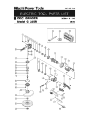
E273 ELECTRIC TOOL PARTS LIST DISC GRINDER Model G 23SR 2006 • 4 • 14 (E1) 501 502 503 1 2 3 4 5 6 7 8 9 10 11 18 12 34 13 35 19 36 14 15 20 37 38 16 17 21 39 22 40 23 41 24 25 42 44 43 26 27 28 29 30 31 32 47 46 45 50 49 48 53 54 52 51 33 55 Hitachi Power Tools LIST NO.
E273 ELECTRIC TOOL PARTS LIST DISC GRINDER Model G 23SR 2006 • 4 • 14 (E1) 501 502 503 1 2 3 4 5 6 7 8 9 10 11 18 12 34 13 35 19 36 14 15 20 37 38 16 17 21 39 22 40 23 41 24 25 42 44 43 26 27 28 29 30 31 32 47 46 45 50 49 48 53 54 52 51 33 55 Hitachi Power Tools LIST NO.
Parts List
Page 2
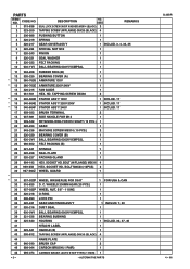
...37 320-216 DUST SEAL 1 38 600-0VV BALL BEARING 6000VVCMPS2L 1 39 321-536 BEARING BUSHING 1 40 325-640 HOUSING 1 INCLUD. 39, 47, 49 41 HITACHI LABEL 1 42 325-641 HANDLE (B) 1 43 305-812 TAPPING SCREW (W/FLANGE) D4X16 (BLACK) 4 44 NAME PLATE 1 45 940-540 BRUSH CAP 2 46... 999-044 CARBON BRUSH (1 PAIR) 1 46 999-074 CARBON BRUSH (AUTO STOP TYPE) (1 PAIR) 1 --- 2 --- * ALTERNATIVE PARTS G 23SR 4 -- 06 TAPPING SCREW D5X60 2 * 16 340-664D STATOR ASS'Y 120V 1 INCLUD. 17 * 16 340-664E STATOR ASS'Y 220V-230V 1 INCLUD. 17 * 16 340-...
...37 320-216 DUST SEAL 1 38 600-0VV BALL BEARING 6000VVCMPS2L 1 39 321-536 BEARING BUSHING 1 40 325-640 HOUSING 1 INCLUD. 39, 47, 49 41 HITACHI LABEL 1 42 325-641 HANDLE (B) 1 43 305-812 TAPPING SCREW (W/FLANGE) D4X16 (BLACK) 4 44 NAME PLATE 1 45 940-540 BRUSH CAP 2 46... 999-044 CARBON BRUSH (1 PAIR) 1 46 999-074 CARBON BRUSH (AUTO STOP TYPE) (1 PAIR) 1 --- 2 --- * ALTERNATIVE PARTS G 23SR 4 -- 06 TAPPING SCREW D5X60 2 * 16 340-664D STATOR ASS'Y 120V 1 INCLUD. 17 * 16 340-664E STATOR ASS'Y 220V-230V 1 INCLUD. 17 * 16 340-...
Parts List
Page 4
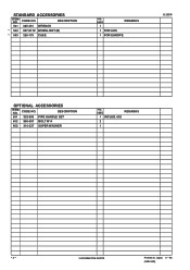
CODE NO. DESCRIPTION 501 325-491 WRENCH * 502 937-917Z WHEEL NUT (B) * 503 326-175 CASE NO. DESCRIPTION 601 323-993 PIPE HANDLE SET 602 985-597 BOLT M14 603 310-337 SUPER WASHER NO. USED 1 REMARKS 1 FOR AUS 1 FOR EUROPE G 23SR OPTIONAL ACCESSORIES ITEM NO. USED REMARKS 1 INCLUD. 602 2 1 --- 4 --- * ALTERNATIVE PARTS Printed in Japan 4 -- 06 (060414N) STANDARD ACCESSORIES ITEM NO. CODE NO.
CODE NO. DESCRIPTION 501 325-491 WRENCH * 502 937-917Z WHEEL NUT (B) * 503 326-175 CASE NO. DESCRIPTION 601 323-993 PIPE HANDLE SET 602 985-597 BOLT M14 603 310-337 SUPER WASHER NO. USED 1 REMARKS 1 FOR AUS 1 FOR EUROPE G 23SR OPTIONAL ACCESSORIES ITEM NO. USED REMARKS 1 INCLUD. 602 2 1 --- 4 --- * ALTERNATIVE PARTS Printed in Japan 4 -- 06 (060414N) STANDARD ACCESSORIES ITEM NO. CODE NO.


