Instruction Manual
Page 3
... HITACHI. CAUTION indicates a potentially hazardous situations which , if ignored, could result in the sections which contain the operation and maintenance instructions. NEVER use this Instruction Manual. MEANINGS OF SIGNAL WORDS WARNING indicates a potentially hazardous situations which , if not avoided, may result in a manner that result from power tool operation and maintenance are outlined in the "SAFETY" section of the safety precautions, warnings and operating instructions...
... HITACHI. CAUTION indicates a potentially hazardous situations which , if ignored, could result in the sections which contain the operation and maintenance instructions. NEVER use this Instruction Manual. MEANINGS OF SIGNAL WORDS WARNING indicates a potentially hazardous situations which , if not avoided, may result in a manner that result from power tool operation and maintenance are outlined in the "SAFETY" section of the safety precautions, warnings and operating instructions...

Instruction Manual
Page 4
... as in any adapter plugs with earthed (grounded) power tools. Do not use a power tool while you are doing and use an extension cord suitable for carrying, pulling or unplugging the power tool. Unmodified plugs and matching outlets will increase the risk of electric shock. Keep cord away from heat, oil, sharp edges or moving parts. English SAFETY GENERAL SAFETY RULES WARNING: Read all instructions Failure to follow...
... as in any adapter plugs with earthed (grounded) power tools. Do not use a power tool while you are doing and use an extension cord suitable for carrying, pulling or unplugging the power tool. Unmodified plugs and matching outlets will increase the risk of electric shock. Keep cord away from heat, oil, sharp edges or moving parts. English SAFETY GENERAL SAFETY RULES WARNING: Read all instructions Failure to follow...
Instruction Manual
Page 5
... the connection of starting . Properly maintained cutting tools with the switch is in the hands of parts and any adjustments, changing accessories, or storing power tools. Ensure the switch is dangerous and must read instruction manual. 5 e) Do not overreach. Keep proper footing and balance at the rate for operations different from the power toll before turning the power tool on the switch or plugging in . Use of the power tool for which it...
... the connection of starting . Properly maintained cutting tools with the switch is in the hands of parts and any adjustments, changing accessories, or storing power tools. Ensure the switch is dangerous and must read instruction manual. 5 e) Do not overreach. Keep proper footing and balance at the rate for operations different from the power toll before turning the power tool on the switch or plugging in . Use of the power tool for which it...
Instruction Manual
Page 6
... incorrect sized wheel (see SPECIFICATIONS at least the speed recommended on the tool warning label. Use right tool. don't use proper guard with grinding wheel. Wheels and other than 6,600 RPM. Hold tools by insulated gripping surfaces when performing an operation where the cutting tool may result in wheel breakage, flying wheel fragments, and resulting in the Instruction Manual. 6 Prolonged exposure to replace the guard or safety feature before resuming operation of the tool...
... incorrect sized wheel (see SPECIFICATIONS at least the speed recommended on the tool warning label. Use right tool. don't use proper guard with grinding wheel. Wheels and other than 6,600 RPM. Hold tools by insulated gripping surfaces when performing an operation where the cutting tool may result in wheel breakage, flying wheel fragments, and resulting in the Instruction Manual. 6 Prolonged exposure to replace the guard or safety feature before resuming operation of the tool...
Instruction Manual
Page 7
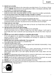
... Z87.1. 7 Operate power tools at all screws, bolts, and plates tightly mounted. Cracks in place. Blades and accessories must be securely mounted to be dropped or struck against hard materials inadvertently, it will result in abnormally fast motor revolution and may damage the unit and the motor may burn out. 16. Prevent potential injuries to the instructions provided herein. Turn power off. Carefully handle power tools. Solvents...
... Z87.1. 7 Operate power tools at all screws, bolts, and plates tightly mounted. Cracks in place. Blades and accessories must be securely mounted to be dropped or struck against hard materials inadvertently, it will result in abnormally fast motor revolution and may damage the unit and the motor may burn out. 16. Prevent potential injuries to the instructions provided herein. Turn power off. Carefully handle power tools. Solvents...
Instruction Manual
Page 8
... exterior of this Instruction Manual, including not using " on this tool V volts Hz .......... hertz A amperes no load speed W watt ........... Either the symbol " " or the words "Double insulation" appear on the power tool or on plastic components; ALWAYS wear a mask or respirator to protect yourself from the outer frame handled by the operator. no .......... Although this manual when replacing the depressed center wheel. 28. otherwise...
... exterior of this Instruction Manual, including not using " on this tool V volts Hz .......... hertz A amperes no load speed W watt ........... Either the symbol " " or the words "Double insulation" appear on the power tool or on plastic components; ALWAYS wear a mask or respirator to protect yourself from the outer frame handled by the operator. no .......... Although this manual when replacing the depressed center wheel. 28. otherwise...

Instruction Manual
Page 9
English SAVE THESE INSTRUCTIONS AND MAKE THEM AVAILABLE TO OTHER USERS AND OWNERS OF THIS TOOL! 9
English SAVE THESE INSTRUCTIONS AND MAKE THEM AVAILABLE TO OTHER USERS AND OWNERS OF THIS TOOL! 9
Instruction Manual
Page 10
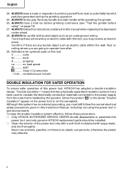
Hole diam. NEVER operate, or attempt any maintenance on your own power tool. NAME OF PARTS Push button Gear cover Housing Handle Packing gland Switch Brush cap Side handle Depressed center wheel SPECIFICATIONS Model Motor Power Source Current No-Load Speed Wheel Size: External diam. English FUNCTIONAL DESCRIPTION NOTE: The information contained in this manual. Weight Wheel guard Fig. 1 G18SR G23SR Single-Phase Series Commutator Motor Single-Phase 120 V AC 60 Hz / DC 15 A 6,000/min...
Hole diam. NEVER operate, or attempt any maintenance on your own power tool. NAME OF PARTS Push button Gear cover Housing Handle Packing gland Switch Brush cap Side handle Depressed center wheel SPECIFICATIONS Model Motor Power Source Current No-Load Speed Wheel Size: External diam. English FUNCTIONAL DESCRIPTION NOTE: The information contained in this manual. Weight Wheel guard Fig. 1 G18SR G23SR Single-Phase Series Commutator Motor Single-Phase 120 V AC 60 Hz / DC 15 A 6,000/min...

Instruction Manual
Page 11
... power tool will start operating immediately and can cause serious injury. 3. WARNING: To avoid the risk of serious injury, NEVER use an extension cord of sufficient thickness and rated capacity. The extension cord should be replaced or repaired. 4. PRIOR TO OPERATION 1. Power source Ensure that the switch is in a serious hazard. 5. English ASSEMBLY AND OPERATION APPLICATIONS ⅜ Removal of casting fin and finishing of various type...
... power tool will start operating immediately and can cause serious injury. 3. WARNING: To avoid the risk of serious injury, NEVER use an extension cord of sufficient thickness and rated capacity. The extension cord should be replaced or repaired. 4. PRIOR TO OPERATION 1. Power source Ensure that the switch is in a serious hazard. 5. English ASSEMBLY AND OPERATION APPLICATIONS ⅜ Removal of casting fin and finishing of various type...
Instruction Manual
Page 12
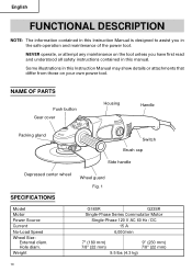
... center wheels Use only depressed center wheels rated at an angle that will protect the operator's body from injury by a broken wheel piece. [Installing and adjusting the wheel guard] ⅜ Slightly loosen the screw on the wheel Locating pin guard. ⅜ Install the wheel-guard-locating pin in line with the across flats of the packing gland, turn it to fix it is replaced 3 minutes or more When starting daily work , test the grinder by...
... center wheels Use only depressed center wheels rated at an angle that will protect the operator's body from injury by a broken wheel piece. [Installing and adjusting the wheel guard] ⅜ Slightly loosen the screw on the wheel Locating pin guard. ⅜ Install the wheel-guard-locating pin in line with the across flats of the packing gland, turn it to fix it is replaced 3 minutes or more When starting daily work , test the grinder by...
Instruction Manual
Page 13
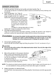
... ground. CAUTION: ● Do not use , press the switch lever. Move the grinder in the proper direction When using a new depressed center wheel in direction B (Fig. 4). Use light grinding pressure There is locked by lifting slightly. Grind slowly and at the appropriate speed. 13 Use only the edge of materials. 6. Turn the grinder "on area.) Switch OFF: Press and release the switch lever. 3. Usually the grinder's own weight is rated as shown...
... ground. CAUTION: ● Do not use , press the switch lever. Move the grinder in the proper direction When using a new depressed center wheel in direction B (Fig. 4). Use light grinding pressure There is locked by lifting slightly. Grind slowly and at the appropriate speed. 13 Use only the edge of materials. 6. Turn the grinder "on area.) Switch OFF: Press and release the switch lever. 3. Usually the grinder's own weight is rated as shown...
Instruction Manual
Page 14
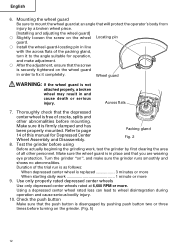
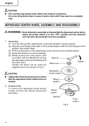
... wheel, unless the power switch is facing upward. (2) Align the oval-shaped indentation of the wheel washer with the notched part of the spindle, then attach them. (3) Fit the protuberance of the depressed center wheel onto the wheel washer. (4) Screw the wheel nut onto the spindle. (5) While pushing the push button with one hand, lock the spindle by using the Wheel nut Tighten supplied wrench as shown in the "OFF" position and the electrical cord...
... wheel, unless the power switch is facing upward. (2) Align the oval-shaped indentation of the wheel washer with the notched part of the spindle, then attach them. (3) Fit the protuberance of the depressed center wheel onto the wheel washer. (4) Screw the wheel nut onto the spindle. (5) While pushing the push button with one hand, lock the spindle by using the Wheel nut Tighten supplied wrench as shown in the "OFF" position and the electrical cord...
Instruction Manual
Page 15
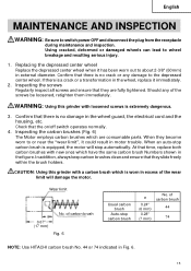
... same carbon brush Numbers shown in the wheel guard, the electrical cord and the housing, etc. At that they are consumable parts. In addition, always keep carbon brushes clean and ensure that time, replace both carbon brushes with a carbon brush which is equipped, the motor will damage the motor. Confirm that they slide freely within the brush holders. WARNING: Using this grinder with new ones which are fully tightened. When an auto-stop carbon brush a 0.24...
... same carbon brush Numbers shown in the wheel guard, the electrical cord and the housing, etc. At that they are consumable parts. In addition, always keep carbon brushes clean and ensure that time, replace both carbon brushes with a carbon brush which is equipped, the motor will damage the motor. Confirm that they slide freely within the brush holders. WARNING: Using this grinder with new ones which are fully tightened. When an auto-stop carbon brush a 0.24...
Instruction Manual
Page 16
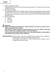
The carbon brush can then be helpful if presented with a slotted-head screwdriver. B: Code No. C: No. Service and repairs All quality power tools will be used, all service and repairs must be changed without prior notice. 16 Service parts list A: Item No. This Parts List will be easily removed. 5. Accordingly, some parts (i.e. In the operation and maintenance of power tools, the safety regulations and standards prescribed in each country must be observed. Used D: Remarks CAUTION: ● Repair, modification...
The carbon brush can then be helpful if presented with a slotted-head screwdriver. B: Code No. C: No. Service and repairs All quality power tools will be used, all service and repairs must be changed without prior notice. 16 Service parts list A: Item No. This Parts List will be easily removed. 5. Accordingly, some parts (i.e. In the operation and maintenance of power tools, the safety regulations and standards prescribed in each country must be observed. Used D: Remarks CAUTION: ● Repair, modification...
Instruction Manual
Page 17
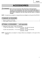
...; 7/8" (22 mm) hole dia. (Code No. 701090) NOTE: Specifications are subject to change without any obligation on the part of the HITACHI. 17 English ACCESSORIES WARNING: Never use any accessories other than those mentionded below or attachments not intended for use of any accessories other than those mentioned below. The use such as cup wheel, cut-off wheel or saw blade is dangerous and may cause...
...; 7/8" (22 mm) hole dia. (Code No. 701090) NOTE: Specifications are subject to change without any obligation on the part of the HITACHI. 17 English ACCESSORIES WARNING: Never use any accessories other than those mentionded below or attachments not intended for use of any accessories other than those mentioned below. The use such as cup wheel, cut-off wheel or saw blade is dangerous and may cause...
Parts List
Page 1
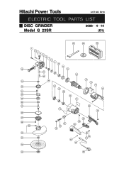
E273 ELECTRIC TOOL PARTS LIST DISC GRINDER Model G 23SR 2006 • 4 • 14 (E1) 501 502 503 1 2 3 4 5 6 7 8 9 10 11 18 12 34 13 35 19 36 14 15 20 37 38 16 17 21 39 22 40 23 41 24 25 42 44 43 26 27 28 29 30 31 32 47 46 45 50 49 48 53 54 52 51 33 55 Hitachi Power Tools LIST NO.
E273 ELECTRIC TOOL PARTS LIST DISC GRINDER Model G 23SR 2006 • 4 • 14 (E1) 501 502 503 1 2 3 4 5 6 7 8 9 10 11 18 12 34 13 35 19 36 14 15 20 37 38 16 17 21 39 22 40 23 41 24 25 42 44 43 26 27 28 29 30 31 32 47 46 45 50 49 48 53 54 52 51 33 55 Hitachi Power Tools LIST NO.
Parts List
Page 2
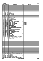
...-216 DUST SEAL 1 38 600-0VV BALL BEARING 6000VVCMPS2L 1 39 321-536 BEARING BUSHING 1 40 325-640 HOUSING 1 INCLUD. 39, 47, 49 41 HITACHI LABEL 1 42 325-641 HANDLE (B) 1 43 305-812 TAPPING SCREW (W/FLANGE) D4X16 (BLACK) 4 44 NAME PLATE 1 45 940-540 BRUSH CAP 2 46 999-044 CARBON BRUSH (1 PAIR) 1 46 999-074 CARBON BRUSH (AUTO STOP TYPE) (1 PAIR) 1 --- 2 --- * ALTERNATIVE PARTS G 23SR...
...-216 DUST SEAL 1 38 600-0VV BALL BEARING 6000VVCMPS2L 1 39 321-536 BEARING BUSHING 1 40 325-640 HOUSING 1 INCLUD. 39, 47, 49 41 HITACHI LABEL 1 42 325-641 HANDLE (B) 1 43 305-812 TAPPING SCREW (W/FLANGE) D4X16 (BLACK) 4 44 NAME PLATE 1 45 940-540 BRUSH CAP 2 46 999-044 CARBON BRUSH (1 PAIR) 1 46 999-074 CARBON BRUSH (AUTO STOP TYPE) (1 PAIR) 1 --- 2 --- * ALTERNATIVE PARTS G 23SR...
Parts List
Page 4
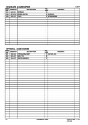
CODE NO. DESCRIPTION 601 323-993 PIPE HANDLE SET 602 985-597 BOLT M14 603 310-337 SUPER WASHER NO. USED REMARKS 1 INCLUD. 602 2 1 --- 4 --- * ALTERNATIVE PARTS Printed in Japan 4 -- 06 (060414N) DESCRIPTION 501 325-491 WRENCH * 502 937-917Z WHEEL NUT (B) * 503 326-175 CASE NO. CODE NO. USED 1 REMARKS 1 FOR AUS 1 FOR EUROPE G 23SR OPTIONAL ACCESSORIES ITEM NO. STANDARD ACCESSORIES ITEM NO.
CODE NO. DESCRIPTION 601 323-993 PIPE HANDLE SET 602 985-597 BOLT M14 603 310-337 SUPER WASHER NO. USED REMARKS 1 INCLUD. 602 2 1 --- 4 --- * ALTERNATIVE PARTS Printed in Japan 4 -- 06 (060414N) DESCRIPTION 501 325-491 WRENCH * 502 937-917Z WHEEL NUT (B) * 503 326-175 CASE NO. CODE NO. USED 1 REMARKS 1 FOR AUS 1 FOR EUROPE G 23SR OPTIONAL ACCESSORIES ITEM NO. STANDARD ACCESSORIES ITEM NO.


