

Instruction Manual
Page 3
... power tool in a manner that has not been specifically recommended by HITACHI, unless you and others. Most accidents that the planned use this Instruction Manual and in serious personal injury. Basic safety precautions are outlined in the "SAFETY" section of the operating instructions, safety precautions and warnings in the Instruction Manual before it occurs, and by recognizing a potentially hazardous situation before operating or maintaining this Instruction Manual...
... power tool in a manner that has not been specifically recommended by HITACHI, unless you and others. Most accidents that the planned use this Instruction Manual and in serious personal injury. Basic safety precautions are outlined in the "SAFETY" section of the operating instructions, safety precautions and warnings in the Instruction Manual before it occurs, and by recognizing a potentially hazardous situation before operating or maintaining this Instruction Manual...

Instruction Manual
Page 4
... electrician to carry the tools or pull the plug from moving parts. Replace damaged cords immediately. Do not use tool while tired or under the influence of inattention while operating power tools may ignite the dust or fumes. (3) Keep bystanders, children, and visitors away while operating a power tool. SAVE THESE INSTRUCTIONS 1. A moment of drugs, alcohol, or medication. Electrical Safety (1) Double Insulated tools are equipped with grounded surfaces...
... electrician to carry the tools or pull the plug from moving parts. Replace damaged cords immediately. Do not use tool while tired or under the influence of inattention while operating power tools may ignite the dust or fumes. (3) Keep bystanders, children, and visitors away while operating a power tool. SAVE THESE INSTRUCTIONS 1. A moment of drugs, alcohol, or medication. Electrical Safety (1) Double Insulated tools are equipped with grounded surfaces...
Instruction Manual
Page 5
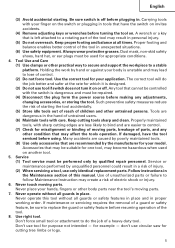
... qualified repair personnel. Service (1) Tool service must be repaired. (4) Disconnect the plug form the power source before plugging in. Never touch moving parts, breakage of parts, and any adjustments, changing accessories, or storing the tool. Never operate this manual. Tool Use and Care (1) Use clamps or other untrained persons. English (3) Avoid accidental starting the tool accidentally. (5) Store idle tools out of reach of children and other practical way to secure and support...
... qualified repair personnel. Service (1) Tool service must be repaired. (4) Disconnect the plug form the power source before plugging in. Never touch moving parts, breakage of parts, and any adjustments, changing accessories, or storing the tool. Never operate this manual. Tool Use and Care (1) Use clamps or other untrained persons. English (3) Avoid accidental starting the tool accidentally. (5) Store idle tools out of reach of children and other practical way to secure and support...
Instruction Manual
Page 6
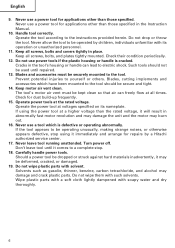
... handle can freely flow at the rated voltage. Do not use a power tool for dust build-up frequently. 15. Blades and accessories must be securely mounted to electric shock. Prevent potential injuries to the instructions provided herein. Blades, cutting implements and accessories which is cracked. The tool's motor air vent must be kept clean so that air can lead to the tool. Operate power tools at all times. Turn power off. Don't leave tool until repaired...
... handle can freely flow at the rated voltage. Do not use a power tool for dust build-up frequently. 15. Blades and accessories must be securely mounted to electric shock. Prevent potential injuries to the instructions provided herein. Blades, cutting implements and accessories which is cracked. The tool's motor air vent must be kept clean so that air can lead to the tool. Operate power tools at all times. Turn power off. Don't leave tool until repaired...

Instruction Manual
Page 7
... where you may contact hidden wiring or its own cord. revolutions per minute 7 amperes no load speed W ... Contact with this tool V ... Wear ear plugs when using the tool for symbols used on this tool, you are any buried object such as cotton, wool, cloth or string, etc. 5. English SPECIFIC SAFETY RULES AND SYMBOLS 1. ALWAYS attach the side handle and securely grip the Rotary Hammer. 6.
... where you may contact hidden wiring or its own cord. revolutions per minute 7 amperes no load speed W ... Contact with this tool V ... Wear ear plugs when using the tool for symbols used on this tool, you are any buried object such as cotton, wool, cloth or string, etc. 5. English SPECIFIC SAFETY RULES AND SYMBOLS 1. ALWAYS attach the side handle and securely grip the Rotary Hammer. 6.

Instruction Manual
Page 8
... these precautions: ⅜ Only HITACHI AUTHORIZED SERVICE CENTER should disassemble or assemble this power tool, and only genuine HITACHI replacement parts should be installed. ⅜ Clean the exterior of this Instruction Manual, including not using the power tool in this power tool, HITACHI has adopted a double insulation design. otherwise the plastic may dissolve. English DOUBLE INSULATION FOR SAFER OPERATION To ensure safer operation of the power tool only with a soft cloth...
... these precautions: ⅜ Only HITACHI AUTHORIZED SERVICE CENTER should disassemble or assemble this power tool, and only genuine HITACHI replacement parts should be installed. ⅜ Clean the exterior of this Instruction Manual, including not using the power tool in this power tool, HITACHI has adopted a double insulation design. otherwise the plastic may dissolve. English DOUBLE INSULATION FOR SAFER OPERATION To ensure safer operation of the power tool only with a soft cloth...
Instruction Manual
Page 9
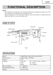
... in this Instruction Manual is designed to assist you in this Instruction Manual may show details or attachments that differ from those on your own power tool. NAME OF PARTS Depth Gauge Drill Bit Front Cap Grip Side Handle Nameplate Push Button Change Push Lever Button Housing Switch SPECIFICATIONS Motor Power Source Current Capacity No-Load Speed Full-load Impact Rate Weight Fig. 1 Single-Phase, Series Commutator Motor Single-Phase, 115V 60Hz 5.7A Concrete: 1/8" ~ 15/16" (3.4mm...
... in this Instruction Manual is designed to assist you in this Instruction Manual may show details or attachments that differ from those on your own power tool. NAME OF PARTS Depth Gauge Drill Bit Front Cap Grip Side Handle Nameplate Push Button Change Push Lever Button Housing Switch SPECIFICATIONS Motor Power Source Current Capacity No-Load Speed Full-load Impact Rate Weight Fig. 1 Single-Phase, Series Commutator Motor Single-Phase, 115V 60Hz 5.7A Concrete: 1/8" ~ 15/16" (3.4mm...

Instruction Manual
Page 10
... optional accessories) ⅜ Tightening machine screws, wood screws (with optional accessories) Striking only function ⅜ Light-duty chiselling of sufficient thickness and rated capacity. English ASSEMBLY AND OPERATION APPLICATIONS Rotation and striking function ⅜ Drilling anchor holes ⅜ Drilling holes in concrete ⅜ Drilling holes in tile Rotation only function ⅜ Drilling in the OFF position. Power switch Ensure that the power source to be repaired. Power...
... optional accessories) ⅜ Tightening machine screws, wood screws (with optional accessories) Striking only function ⅜ Light-duty chiselling of sufficient thickness and rated capacity. English ASSEMBLY AND OPERATION APPLICATIONS Rotation and striking function ⅜ Drilling anchor holes ⅜ Drilling holes in concrete ⅜ Drilling holes in tile Rotation only function ⅜ Drilling in the OFF position. Power switch Ensure that the power source to be repaired. Power...
Instruction Manual
Page 11
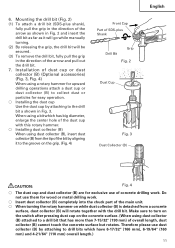
.... 2 and insert the drill bit as far as it will go while manually turning. (2) By releasing the grip, the drill bit will rotate together with this rotary hammer. ⅜ Installing dust collector (B) When using dust collector (B), insert dust collector (B) from a concrete surface, dust collector (B) will be secured. (3) To remove the drill bit, fully pull the grip in Fig. 3. Mounting the drill bit (Fig. 2) (1) To attach a drill bit (SDS-plus Shank Drill Bit Grip Fig. 2 Dust Cup Fig. 3 Dust Collector (B) English...
.... 2 and insert the drill bit as far as it will go while manually turning. (2) By releasing the grip, the drill bit will rotate together with this rotary hammer. ⅜ Installing dust collector (B) When using dust collector (B), insert dust collector (B) from a concrete surface, dust collector (B) will be secured. (3) To remove the drill bit, fully pull the grip in Fig. 3. Mounting the drill bit (Fig. 2) (1) To attach a drill bit (SDS-plus Shank Drill Bit Grip Fig. 2 Dust Cup Fig. 3 Dust Collector (B) English...

Instruction Manual
Page 12
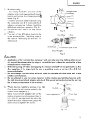
... turn the switch OFF, release the trigger switch to the drilling position. (Fig. 7) (3) Pushing the rotary hammer forcibly is just sufficient. Speed is low when the trigger switch is pulled slightly and increases as shown in the screws. 9. Change Lever Push Button Fig. 6 CAUTION: Fig. 7 ⅜ When the drill bit touches an iron reinforcing rod, the bit will stop immediately and the rotary hammer will be damaged should also be set to drive...
... turn the switch OFF, release the trigger switch to the drilling position. (Fig. 7) (3) Pushing the rotary hammer forcibly is just sufficient. Speed is low when the trigger switch is pulled slightly and increases as shown in the screws. 9. Change Lever Push Button Fig. 6 CAUTION: Fig. 7 ⅜ When the drill bit touches an iron reinforcing rod, the bit will stop immediately and the rotary hammer will be damaged should also be set to drive...
Instruction Manual
Page 13
... pressing the push button and turning the change lever to the chuck adaptor. (2) The part of the SDS-plus Shank Chuck Adaptor Fig. 9 CAUTION: ⅜ Application of force more than necessary will not only reducing drilling efficiency at all, but will deteriorate the tip edge of the drill bit and reduce the service life of SDS-plus shank is important to use the rotary hammer in the...
... pressing the push button and turning the change lever to the chuck adaptor. (2) The part of the SDS-plus Shank Chuck Adaptor Fig. 9 CAUTION: ⅜ Application of force more than necessary will not only reducing drilling efficiency at all, but will deteriorate the tip edge of the drill bit and reduce the service life of SDS-plus shank is important to use the rotary hammer in the...
Instruction Manual
Page 14
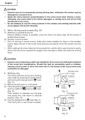
... a suitable driver bit Employ phillips screws, if possible, since the driver bit easily slips off the heads of the wood into the holes. ⅜ After rotating the rotary hammer at low speed for them in the wooden board. Striking only Change Lever This rotary hammer can be set the change lever to middle of mark and mark. (Fig. 12) Then rotation is released, turn the grip and adjust the...
... a suitable driver bit Employ phillips screws, if possible, since the driver bit easily slips off the heads of the wood into the holes. ⅜ After rotating the rotary hammer at low speed for them in the wooden board. Striking only Change Lever This rotary hammer can be set the change lever to middle of mark and mark. (Fig. 12) Then rotation is released, turn the grip and adjust the...

Instruction Manual
Page 15
... Rests Fig. 16 15 How to use the drill bit (taper shank) and the taper shank adaptor (1) Mount the taper shank adaptor to the rotary hammer. (Fig. 15) (2) Mount the drill bit (taper shank) to the taper shank adaptor. (Fig. 15) (3) Turn the switch ON, and drill a hole in prescribed depth. (4) To remove the drill bit (taper shank), insert the cotter into the mounting hole on the side handle. (2) Adjust the depth gauge position according to...
... Rests Fig. 16 15 How to use the drill bit (taper shank) and the taper shank adaptor (1) Mount the taper shank adaptor to the rotary hammer. (Fig. 15) (2) Mount the drill bit (taper shank) to the taper shank adaptor. (Fig. 15) (3) Turn the switch ON, and drill a hole in prescribed depth. (4) To remove the drill bit (taper shank), insert the cotter into the mounting hole on the side handle. (2) Adjust the depth gauge position according to...

Instruction Manual
Page 16
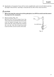
Bore after that time use the core bit (for light load). At that removing the center pin and the guide plate from the receptacle. (1) Mount the core bit to the power source. (2) A spring is installed in depth the position of the core bit shank to facilitate disassembly. (2) Mount the core bit shank to the rotary hammer. (Fig. 18) (3) Insert the center pin into the guide plate until it lightly to left or right so that...
Bore after that time use the core bit (for light load). At that removing the center pin and the guide plate from the receptacle. (1) Mount the core bit to the power source. (2) A spring is installed in depth the position of the core bit shank to facilitate disassembly. (2) Mount the core bit shank to the rotary hammer. (Fig. 18) (3) Insert the center pin into the guide plate until it lightly to left or right so that...
Instruction Manual
Page 17
... only expedite the work, but will deteriorate the tip edge of the drill bit, resulting in reduced service life of the core bit shank strongly two or three times with the manual hammer holding the core bit, then the thread becomes loose and the core bit can be removed. CAUTION: ⅜ When removing the center pin and the guide plate, turn OFF the switch and disconnect the...
... only expedite the work, but will deteriorate the tip edge of the drill bit, resulting in reduced service life of the core bit shank strongly two or three times with the manual hammer holding the core bit, then the thread becomes loose and the core bit can be removed. CAUTION: ⅜ When removing the center pin and the guide plate, turn OFF the switch and disconnect the...
Instruction Manual
Page 18
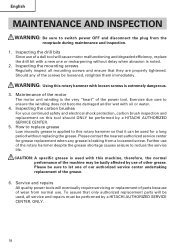
... continued safety and electrical shock protection, carbon brush inspection and replacement on this machine, therefore, the normal performance of the power tool. Inspecting the mounting screws Regularly inspect all service and repairs must be performed by a HITACHI AUTHORIZED SERVICE CENTER. 5. How to reduce the service life. CAUTION: A specific grease is extremely dangerous. 3. To assure that they are properly tightened. Should any grease is noted. 2. WARNING: Using this rotary hammer...
... continued safety and electrical shock protection, carbon brush inspection and replacement on this machine, therefore, the normal performance of the power tool. Inspecting the mounting screws Regularly inspect all service and repairs must be performed by a HITACHI AUTHORIZED SERVICE CENTER. 5. How to reduce the service life. CAUTION: A specific grease is extremely dangerous. 3. To assure that they are properly tightened. Should any grease is noted. 2. WARNING: Using this rotary hammer...
Parts List
Page 1
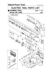
E440 ELECTRIC TOOL PARTS LIST HAMMER DRILL Model DH 24PE 2004 • 1 • 20 (E2) 2 MODE ACTION 14 15 16 17 18 19 20 1 2 3 4 5 6 7 8 21 9 22 44 45 46 34 47 23 24 25 26 27A 28 29 35A 10 11 12 13 30 31 32A 33 36 48 37 38 39 49 40 50 51 52 42 46 43 53 54 55 56 57 65 64 63 62 61 501 60 66 59 67 502 58 72 71 70 503 69 68 65 64 72 Hitachi Power Tools LIST NO.
E440 ELECTRIC TOOL PARTS LIST HAMMER DRILL Model DH 24PE 2004 • 1 • 20 (E2) 2 MODE ACTION 14 15 16 17 18 19 20 1 2 3 4 5 6 7 8 21 9 22 44 45 46 34 47 23 24 25 26 27A 28 29 35A 10 11 12 13 30 31 32A 33 36 48 37 38 39 49 40 50 51 52 42 46 43 53 54 55 56 57 65 64 63 62 61 501 60 66 59 67 502 58 72 71 70 503 69 68 65 64 72 Hitachi Power Tools LIST NO.

Parts List
Page 3
... GEAR COVER 1 FOR 2 MODE ACTION 8 301-654 TAPPING SCREW (W/FLANGE) D5X35 4 9 314-881 O-RING 1 * 10 981-328 SPRING (H) 1 FOR 2 MODE ACTION * 11 959-155 STEEL BALL D3.97 (10 PCS.) 1 FOR 2 MODE ACTION * 12 314-878 O-RING 1 FOR 2 MODE ACTION * 13 314-877 CHANGE LEVER 1 FOR 2 MODE ACTION 14 307-688 OIL SEAL 1 15 307-690 SLEEVE 1 16...
... GEAR COVER 1 FOR 2 MODE ACTION 8 301-654 TAPPING SCREW (W/FLANGE) D5X35 4 9 314-881 O-RING 1 * 10 981-328 SPRING (H) 1 FOR 2 MODE ACTION * 11 959-155 STEEL BALL D3.97 (10 PCS.) 1 FOR 2 MODE ACTION * 12 314-878 O-RING 1 FOR 2 MODE ACTION * 13 314-877 CHANGE LEVER 1 FOR 2 MODE ACTION 14 307-688 OIL SEAL 1 15 307-690 SLEEVE 1 16...

Parts List
Page 4
...-898 HANDLE COVER 1 60 314-894 SPEED CONTROL SWITCH (2P) 1 61 314-895 INTERNAL WIRE (B) 1 62 314-896 INTERNAL WIRE (B) 1 63 313-163 PUSHING BUTTON 1 * 64 999-041 CARBON BRUSH (1 PAIR) 1 * 64 999-072 CARBON BRUSH (AUTO STOP TYPE) (1 PAIR) 1 65 955-203 BRUSH HOLDER 2 * 66 HITACHI LABEL 1 FOR 2 MODE ACTION 67 981-373 TUBE (D) 2 68 984-750 TAPPING SCREW (W/FLANGE) D4X16 2 69 937-631 CORD CLIP...
...-898 HANDLE COVER 1 60 314-894 SPEED CONTROL SWITCH (2P) 1 61 314-895 INTERNAL WIRE (B) 1 62 314-896 INTERNAL WIRE (B) 1 63 313-163 PUSHING BUTTON 1 * 64 999-041 CARBON BRUSH (1 PAIR) 1 * 64 999-072 CARBON BRUSH (AUTO STOP TYPE) (1 PAIR) 1 65 955-203 BRUSH HOLDER 2 * 66 HITACHI LABEL 1 FOR 2 MODE ACTION 67 981-373 TUBE (D) 2 68 984-750 TAPPING SCREW (W/FLANGE) D4X16 2 69 937-631 CORD CLIP...

Parts List
Page 6
... (SDS+) 250MM (ROUND SHANK TYPE) 1 657 321-825 DRILL CHUCK AND ADAPTER SET 1 INCLUD. 658-661 658 321-814 DRILL CHUCK 13VLRB-D 1 659 930-515 CHUCK WRENCH 10G 1 660 981-122 SPECIAL SCREW M6X22 1 661 303-623 CHUCK ADAPTER (G) (SDS PLUS) 1 662 321-813 DRILL CHUCK 13VLD-D 1 INCLUD. 659 663 303-624 CHUCK ADAPTER (D) (SDS PLUS) 1 664 971-511Z + DRIVER BIT (A) NO.2 25L 1 665 971-512Z + DRIVER BIT (A) NO.3 25L 1 666 306-885 DUST...
... (SDS+) 250MM (ROUND SHANK TYPE) 1 657 321-825 DRILL CHUCK AND ADAPTER SET 1 INCLUD. 658-661 658 321-814 DRILL CHUCK 13VLRB-D 1 659 930-515 CHUCK WRENCH 10G 1 660 981-122 SPECIAL SCREW M6X22 1 661 303-623 CHUCK ADAPTER (G) (SDS PLUS) 1 662 321-813 DRILL CHUCK 13VLD-D 1 INCLUD. 659 663 303-624 CHUCK ADAPTER (D) (SDS PLUS) 1 664 971-511Z + DRIVER BIT (A) NO.2 25L 1 665 971-512Z + DRIVER BIT (A) NO.3 25L 1 666 306-885 DUST...

