

Service Manual
Page 2
... Pin Assignment 8 6. Image Engine ( Zoom 19 LCD Panel Specification 1 B. Features ...7 C. Description ...13 B. Connector Type 13 E. Power Management 2 D. Measuring Apparatuses Used 5 B. Adjustment of Plug and Play 19 C. ADJUSTMENT OF BOARDS 6 A. VK-526 CONTROL PANEL AND... Connector and Switch Locations 13 D. Controls...2 C. Display Modes for Inspections 4 2. ADJUSTMENT OF POWER SUPPLY 6 A. VL-531 DISPLAY CONTROL BOARD 7 A. VP-531 POWER BOARD 16 A. Connector locations 17 8. Description ...16 B. Circuit of Switching Regulator 6 4. Electrical...
... Pin Assignment 8 6. Image Engine ( Zoom 19 LCD Panel Specification 1 B. Features ...7 C. Description ...13 B. Connector Type 13 E. Power Management 2 D. Measuring Apparatuses Used 5 B. Adjustment of Plug and Play 19 C. ADJUSTMENT OF BOARDS 6 A. VK-526 CONTROL PANEL AND... Connector and Switch Locations 13 D. Controls...2 C. Display Modes for Inspections 4 2. ADJUSTMENT OF POWER SUPPLY 6 A. VL-531 DISPLAY CONTROL BOARD 7 A. VP-531 POWER BOARD 16 A. Connector locations 17 8. Description ...16 B. Circuit of Switching Regulator 6 4. Electrical...

Service Manual
Page 3
Power Regulator 19 9. Front Panel Control and Led 20 B. Rear Panel connector Input Signals 21 10. Main Procedure 22 APPENDIX A: DISPLAY UNIT ASSEMBLY 27 APPENDIX B: PCB ASSEMBLY 29 E. INTRODUCTION 20 A. TROUBLESHOOTING 22 A.
Power Regulator 19 9. Front Panel Control and Led 20 B. Rear Panel connector Input Signals 21 10. Main Procedure 22 APPENDIX A: DISPLAY UNIT ASSEMBLY 27 APPENDIX B: PCB ASSEMBLY 29 E. INTRODUCTION 20 A. TROUBLESHOOTING 22 A.

Service Manual
Page 5
... temperature: -20ºC to 65ºC Storage humidity: 10%~90% 1 LCD Panel Specification Display: Compatibility: Synchronization Frequencies: Resolution: Active Display Area: Viewing Angles: Display Colors: Power Supply: Power Consumption: Environmental: 15 inch (15" viewable image size): active matrix: thin film transistor (TFT): liquid crystal display (LCD): 0.297 mm dot pitch: R.G.B. 1.
... temperature: -20ºC to 65ºC Storage humidity: 10%~90% 1 LCD Panel Specification Display: Compatibility: Synchronization Frequencies: Resolution: Active Display Area: Viewing Angles: Display Colors: Power Supply: Power Consumption: Environmental: 15 inch (15" viewable image size): active matrix: thin film transistor (TFT): liquid crystal display (LCD): 0.297 mm dot pitch: R.G.B. 1.

Service Manual
Page 6
... Video Supply On Pulses Pulses Active On Stand-by No Pulses Pulses Blanking Suspend Pulses No Pulses Off No pulses No pulses Blacking On DC Power off Don't care Don't care Don't care Off Video Circuit On Off LCD On Off Off Off LED Green Yellow Yellow Off 2 Adjust decrease. 3. Function...
... Video Supply On Pulses Pulses Active On Stand-by No Pulses Pulses Blanking Suspend Pulses No Pulses Off No pulses No pulses Blacking On DC Power off Don't care Don't care Don't care Off Video Circuit On Off LCD On Off Off Off LED Green Yellow Yellow Off 2 Adjust decrease. 3. Function...

Service Manual
Page 7
LED Dark (DC power off) C-3 Power Consumption Meet VESA DPMS Proposal On mode Stand-by Suspend Off mode DC power off disconnection 25 Wmax 5 Wmax 5 Wmax 5 Wmax 5 Wmax 5 Wmax Measured from AC input end of AC power adapter, and not include audio at power-saving state The stand-by Suspend Off mode DC power off disconnection LED Green Yellow Yellow Yellow Dark 1. suspend; off mode) 2. C-2 LED definition Table State On mode Stand-by , suspend and off mode recover to on mode about 3 seconds. 3 Yellow(stand-by;
LED Dark (DC power off) C-3 Power Consumption Meet VESA DPMS Proposal On mode Stand-by Suspend Off mode DC power off disconnection 25 Wmax 5 Wmax 5 Wmax 5 Wmax 5 Wmax 5 Wmax Measured from AC input end of AC power adapter, and not include audio at power-saving state The stand-by Suspend Off mode DC power off disconnection LED Green Yellow Yellow Yellow Dark 1. suspend; off mode) 2. C-2 LED definition Table State On mode Stand-by , suspend and off mode recover to on mode about 3 seconds. 3 Yellow(stand-by;

Service Manual
Page 8
D. Display Modes FOR Inspections D-1 Supported Timing(for Not supported timing will go to power saving mode)T TIMING 640x350 VGA-350 640x400 NEC PC9801 640x400 VGA-GRAPH 640x400 NEC PC9821 640x480 VGA-480 640x480 VESA-480-72Hz 640x480 VESA-480-...
D. Display Modes FOR Inspections D-1 Supported Timing(for Not supported timing will go to power saving mode)T TIMING 640x350 VGA-350 640x400 NEC PC9801 640x400 VGA-GRAPH 640x400 NEC PC9821 640x480 VGA-480 640x480 VESA-480-72Hz 640x480 VESA-480-...

Service Manual
Page 10
Adjustment of Switching Regulator (Adapter) A-1 Specifications Input voltage Rated input voltage Frequency Rated frequency DC output AC 100 ~ 240Vac AC 90 ~ 264Vac 50 / 60 Hz 47 ~ 63 Hz Out voltage Maximum output current Minimum output current Range of Power Supply A. ADJUSTMENT of voltage Regulation +12V 3.33A 0A ±5% 6 3.
Adjustment of Switching Regulator (Adapter) A-1 Specifications Input voltage Rated input voltage Frequency Rated frequency DC output AC 100 ~ 240Vac AC 90 ~ 264Vac 50 / 60 Hz 47 ~ 63 Hz Out voltage Maximum output current Minimum output current Range of Power Supply A. ADJUSTMENT of voltage Regulation +12V 3.33A 0A ±5% 6 3.

Service Manual
Page 11
R.G.B Signal Cable 2. Control Cable 6. LCD Lamp Cable 8. ADJUSTMENT OF BOARDS Equipment is connected with boards to diagram below. Audio Signal Cable 3. EAR phone Cable 7 A. DC Power Cable 4. Audio Cable 7. Inverter Cable 5. Connection Method 1. 4. Refer to be inspected before adjustments.
R.G.B Signal Cable 2. Control Cable 6. LCD Lamp Cable 8. ADJUSTMENT OF BOARDS Equipment is connected with boards to diagram below. Audio Signal Cable 3. EAR phone Cable 7 A. DC Power Cable 4. Audio Cable 7. Inverter Cable 5. Connection Method 1. 4. Refer to be inspected before adjustments.

Service Manual
Page 14
... 0R4 0R3 0R2 0R1 0R0 GND CPH2 GND GND NC NC VGH NC VGL NC VGC NC NC NC GND GND Function Digital Power Input (DC+3.3V) Digital Power Input (DC+3.3V) Ground Ground Odd-dot Blue Data bit 5 (MSB) Odd-dot Blue Data bit 4 Odd-dot Blue Data bit 3 Odd-dot...
... 0R4 0R3 0R2 0R1 0R0 GND CPH2 GND GND NC NC VGH NC VGL NC VGC NC NC NC GND GND Function Digital Power Input (DC+3.3V) Digital Power Input (DC+3.3V) Ground Ground Odd-dot Blue Data bit 5 (MSB) Odd-dot Blue Data bit 4 Odd-dot Blue Data bit 3 Odd-dot...

Service Manual
Page 15
F-3 CN2 Terminal No. Symbol 31 POL 2 VDD2 Analog Power Input (DC+9V) 32 REV 3 GND Ground 33 GND 4 GND Ground 34 GND 5 EB5 Even-dot Blue Data bit 5(MSB) 35 STV1 6 EB4 Even-dot ... Control Signal Ground Ground Vertical start Pulse1 Vertical start Pulse2 Vertical Clock Input Gate Driver Output Enable Signal Ground Ground 11 Symbol Function 1 VDD2 Analog Power Input (DC+9V) Terminal No.
F-3 CN2 Terminal No. Symbol 31 POL 2 VDD2 Analog Power Input (DC+9V) 32 REV 3 GND Ground 33 GND 4 GND Ground 34 GND 5 EB5 Even-dot Blue Data bit 5(MSB) 35 STV1 6 EB4 Even-dot ... Control Signal Ground Ground Vertical start Pulse1 Vertical start Pulse2 Vertical Clock Input Gate Driver Output Enable Signal Ground Ground 11 Symbol Function 1 VDD2 Analog Power Input (DC+9V) Terminal No.

Service Manual
Page 16
F-4 J2 Pin NO. 1 2 3 4 5 6 7 8 9 10 F-5 J3 Pin NO. 1 2 3 4 5 6 7 Signal NONE LED-Y LED-G GND KEY-UP KEY-Down KEY-R KEY-L KEY-POWER GND Signal +5V +5V GND GND BLON MUTE BRIGHT Comment Power saving mode Monitor is ON GND Function select counter-clockwise key Function select counter-clockwise key Adjust up key Adjust down key Power ON/OFF key GND Comment VL531 power input VL531 power input Ground Ground Back Light ON/OFF. Audio amplifier control signal Brightness Adjustment. 12
F-4 J2 Pin NO. 1 2 3 4 5 6 7 8 9 10 F-5 J3 Pin NO. 1 2 3 4 5 6 7 Signal NONE LED-Y LED-G GND KEY-UP KEY-Down KEY-R KEY-L KEY-POWER GND Signal +5V +5V GND GND BLON MUTE BRIGHT Comment Power saving mode Monitor is ON GND Function select counter-clockwise key Function select counter-clockwise key Adjust up key Adjust down key Power ON/OFF key GND Comment VL531 power input VL531 power input Ground Ground Back Light ON/OFF. Audio amplifier control signal Brightness Adjustment. 12

Service Manual
Page 17
...-1113 J2 SCJ-0348-C J3 87502-0200 J4 87502-0200 J5 96113-1013 Maker E&T SC ACES ACES E&T Number of speakers .When in power saving mode the audio circuit can be turned off by the control signal from VP-531 board. Connector and Switch Locations D. Max. Input Voltage... 2 10 13 B. Description The VK-526 is designed to offer an user interfaced control panel which passes and receives signals to and from VP-531 power board .Also there is a stereo audio amplifier to Noise ratio 500mVrms 1KHz -60dB Cross talk 100mVrms 1KHz -30dB Distortion 500mVrms 1KHz 1% Output Watt....
...-1113 J2 SCJ-0348-C J3 87502-0200 J4 87502-0200 J5 96113-1013 Maker E&T SC ACES ACES E&T Number of speakers .When in power saving mode the audio circuit can be turned off by the control signal from VP-531 board. Connector and Switch Locations D. Max. Input Voltage... 2 10 13 B. Description The VK-526 is designed to offer an user interfaced control panel which passes and receives signals to and from VP-531 power board .Also there is a stereo audio amplifier to Noise ratio 500mVrms 1KHz -60dB Cross talk 100mVrms 1KHz -30dB Distortion 500mVrms 1KHz 1% Output Watt....
Service Manual
Page 18
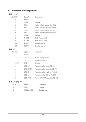
... OUT R Audio volume adjust line OUT L Ground EAR Phone out R EAR Phone out L Speaker out R Speaker out L E-2 J2 Pin NO. 1 2 3 Signal NONE LED-Y LED-G Comment Power saving mode. E. Monitor on mode. 4,10 GND Ground 5 KEY-UP Function select up to VL-531 6 KEY-DOWN Function select down to VL-531 7 KEY...-R Function select right to VL-531 8 KEY-L Function select left to VL-531 9 KEY-PWR Power ON/OFF signal to VL-531 E-3 J3 and J4 Pin NO. 1 2 Signal GND OUTL(OUTR) Comment Ground Speaker out 14
... OUT R Audio volume adjust line OUT L Ground EAR Phone out R EAR Phone out L Speaker out R Speaker out L E-2 J2 Pin NO. 1 2 3 Signal NONE LED-Y LED-G Comment Power saving mode. E. Monitor on mode. 4,10 GND Ground 5 KEY-UP Function select up to VL-531 6 KEY-DOWN Function select down to VL-531 7 KEY...-R Function select right to VL-531 8 KEY-L Function select left to VL-531 9 KEY-PWR Power ON/OFF signal to VL-531 E-3 J3 and J4 Pin NO. 1 2 Signal GND OUTL(OUTR) Comment Ground Speaker out 14

Service Manual
Page 19
... 1 LO NC RI 1 RO I/O Comment Ground Earphone out L Earphone out R Earphone out L Speaker out L No connector Earphone out R Speaker out R E-5 Switch definition Location Definition S1 Power ON/OFF S2 Function select by clockwise direction S3 Function select by ; Yellow for ON mode; stand by counter-clockwise direction S4 Adjust up S5...
... 1 LO NC RI 1 RO I/O Comment Ground Earphone out L Earphone out R Earphone out L Speaker out L No connector Earphone out R Speaker out R E-5 Switch definition Location Definition S1 Power ON/OFF S2 Function select by clockwise direction S3 Function select by ; Yellow for ON mode; stand by counter-clockwise direction S4 Adjust up S5...

Service Manual
Page 20
... IL=6.0Ma(ms) and fL=30 KHz until one of LCD module. VP-531 POWER BOARD A. load Min. TYP. 12V 0.85A MAX. 12.6V 1A COMMENT Vin=12V MAX. Description The VP-531 power board is designed for lighting up the back-lights of the following event occurs: 1.... at 0°C becomes higher than the maximal value of Vs specified above B-2 DC/DC power B.2.1 Input 12V ±5% from adaptor B.2.2 Output Item Vcc Output voltage max. BRIGHTNESS NO LOAD BACKLIGHT VOLTAGE -------- 640V rms. -------- When the startup voltage...
... IL=6.0Ma(ms) and fL=30 KHz until one of LCD module. VP-531 POWER BOARD A. load Min. TYP. 12V 0.85A MAX. 12.6V 1A COMMENT Vin=12V MAX. Description The VP-531 power board is designed for lighting up the back-lights of the following event occurs: 1.... at 0°C becomes higher than the maximal value of Vs specified above B-2 DC/DC power B.2.1 Input 12V ±5% from adaptor B.2.2 Output Item Vcc Output voltage max. BRIGHTNESS NO LOAD BACKLIGHT VOLTAGE -------- 640V rms. -------- When the startup voltage...

Service Manual
Page 23
... controller chip. Micro-Controller Circuit The U5 (s9050-100) is 14.318MHz XTAL. C. System Clock The Y1 (14.318MHz XTAL) supports U5 (Sage) reference clock. Power Regulator (1)The U12(APL117) is 1A linear regulator that transfer input voltage from 5V to 3.3V supports U5. (2)The U13(AIC1084) is 5A linear regulator...
... controller chip. Micro-Controller Circuit The U5 (s9050-100) is 14.318MHz XTAL. C. System Clock The Y1 (14.318MHz XTAL) supports U5 (Sage) reference clock. Power Regulator (1)The U12(APL117) is 1A linear regulator that transfer input voltage from 5V to 3.3V supports U5. (2)The U13(AIC1084) is 5A linear regulator...

Service Manual
Page 24
Yellow indicates DC power off mode. 3 Function Button Launches OSD function menu circully 4 5 Plus Button Selects and adjusts the functions 6 Minus Button Selects and adjusts the functions 20 Introduction A. 9. Amber indicates stand-by, suspend, off . 3. Green indicates monitor is turns on and off. 2 Power LED 1. Front Panel Control and Led Front Panel Controls Item Control Function 1 Power Switch Turns rhe monitor on . 2.
Yellow indicates DC power off mode. 3 Function Button Launches OSD function menu circully 4 5 Plus Button Selects and adjusts the functions 6 Minus Button Selects and adjusts the functions 20 Introduction A. 9. Amber indicates stand-by, suspend, off . 3. Green indicates monitor is turns on and off. 2 Power LED 1. Front Panel Control and Led Front Panel Controls Item Control Function 1 Power Switch Turns rhe monitor on . 2.

Service Manual
Page 25
Rear Panel connector Input Signals Item 1 2 3 Rear Panel Cable and Connector Cable / Connector Function Signal Connector Connectors the video cable Audio Connector Connector the audio cable Power Connector Connectors the adapter cable 21 B.
Rear Panel connector Input Signals Item 1 2 3 Rear Panel Cable and Connector Cable / Connector Function Signal Connector Connectors the video cable Audio Connector Connector the audio cable Power Connector Connectors the adapter cable 21 B.

Service Manual
Page 27
A-1 Power Circuit Troubleshooting 23
A-1 Power Circuit Troubleshooting 23

