
Instruction Manual
Page 3
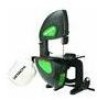
... Cutting Capacity Throat 9 3/8″ Height 5″ Blade Width 1/4″, 3/8″ Length 63 1/2″ Table Size 11 3/4″ x 11 3/4″ Tilt 0° - 45° Left DUST COLLECTION Yes NET WEIGHT 68LB (30.6 kg) WARNING To avoid electrical hazards, fire hazards, or damage to the ...• Crystalline silica from these chemicals are specially designed to a 120V, 15 AMP branch circuit and use proper circuit protection. Your Band Saw is worn, cut or damaged in a well-ventilated area and work . SAVE THESE INSTRUCTIONS -3- To reduce your tools. Connect to...
... Cutting Capacity Throat 9 3/8″ Height 5″ Blade Width 1/4″, 3/8″ Length 63 1/2″ Table Size 11 3/4″ x 11 3/4″ Tilt 0° - 45° Left DUST COLLECTION Yes NET WEIGHT 68LB (30.6 kg) WARNING To avoid electrical hazards, fire hazards, or damage to the ...• Crystalline silica from these chemicals are specially designed to a 120V, 15 AMP branch circuit and use proper circuit protection. Your Band Saw is worn, cut or damaged in a well-ventilated area and work . SAVE THESE INSTRUCTIONS -3- To reduce your tools. Connect to...

Instruction Manual
Page 4
... using your product will operate properly and perform its operation. Make sure switch is a combination of power that it was not designed. 10. WEAR PROPER APPAREL. Cluttered areas and benches invite accidents. 5. Use clamps or a vise to carry the current your hand and it...become familiar with padlocks, master switches, or by removing starter keys. 8. MAKE WORKSHOP CHILDPROOF with the entire Operator's Manual. Any Band Saw can be kept at HITACHI. It's safer than using an extension cord, be carefully checked to use of moving parts. Wear protective hair covering to a ...
... using your product will operate properly and perform its operation. Make sure switch is a combination of power that it was not designed. 10. WEAR PROPER APPAREL. Cluttered areas and benches invite accidents. 5. Use clamps or a vise to carry the current your hand and it...become familiar with padlocks, master switches, or by removing starter keys. 8. MAKE WORKSHOP CHILDPROOF with the entire Operator's Manual. Any Band Saw can be kept at HITACHI. It's safer than using an extension cord, be carefully checked to use of moving parts. Wear protective hair covering to a ...
Instruction Manual
Page 5
...it immediately. If there is excessive vibration or unusual noise, stop before operating the band saw is necessary, DO NOT connect the equipment-grounding conductor to protect the operator from sliding...parts are under the blade guard. 13. Adjust upper guide to support the workpiece. 10. Hold the workpiece firmly against the table. GROUNDING INSTRUCTIONS WARNING This tool must be... damaged in any jammed material, turn the saw is 1/8 inch above the workpiece. 7. CUT only one workpiece at 3600 FPM or greater. 5. Turn the saw to a support surface to prevent accidental injury...
...it immediately. If there is excessive vibration or unusual noise, stop before operating the band saw is necessary, DO NOT connect the equipment-grounding conductor to protect the operator from sliding...parts are under the blade guard. 13. Adjust upper guide to support the workpiece. 10. Hold the workpiece firmly against the table. GROUNDING INSTRUCTIONS WARNING This tool must be... damaged in any jammed material, turn the saw is 1/8 inch above the workpiece. 7. CUT only one workpiece at 3600 FPM or greater. 5. Turn the saw to a support surface to prevent accidental injury...
Instruction Manual
Page 6
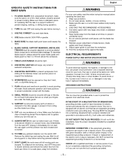
... extension cord is in Figure A showing a 3-prong electrical plug and receptacle that MUST be used to temporarily connect this plug to a Known Ground WARNING This Band Saw is for use in feet More Than Not More Than 25′ 50′ 100′ 150′ 0 6 18 16 16 14... 6 10 18 16 14 12 10 12 16 16 14 12 12 16 14 12 Not Applicable 2-Prong Receptacle -6- Do not expose to a permanent earth ground, such as the current stamped...
... extension cord is in Figure A showing a 3-prong electrical plug and receptacle that MUST be used to temporarily connect this plug to a Known Ground WARNING This Band Saw is for use in feet More Than Not More Than 25′ 50′ 100′ 150′ 0 6 18 16 16 14... 6 10 18 16 14 12 10 12 16 16 14 12 12 16 14 12 Not Applicable 2-Prong Receptacle -6- Do not expose to a permanent earth ground, such as the current stamped...

Instruction Manual
Page 7
...help whenever you are assembling or adjusting the saw. • Although compact, this Band Saw. • Follow instructions that accessory. Crank Handle D. CARTON CONTENTS UNPACKING AND CHECKING CONTENTS Carefully unpack the Band Saw and all its parts, and compare against ... Battery QUANTITY 1 1 1 1 1 1 1 -7- Pointer E. Dust Bag G. Place the saw on a secure surface and examine it carefully. TABLE OF LOOSE PARTS ITEM DESCRIPTION BAND SAW: A. English ACCESSORIES AND ATTACHMENTS RECOMMENDED ACCESSORIES WARNING To avoid injury: • Use only accessories...
...help whenever you are assembling or adjusting the saw. • Although compact, this Band Saw. • Follow instructions that accessory. Crank Handle D. CARTON CONTENTS UNPACKING AND CHECKING CONTENTS Carefully unpack the Band Saw and all its parts, and compare against ... Battery QUANTITY 1 1 1 1 1 1 1 -7- Pointer E. Dust Bag G. Place the saw on a secure surface and examine it carefully. TABLE OF LOOSE PARTS ITEM DESCRIPTION BAND SAW: A. English ACCESSORIES AND ATTACHMENTS RECOMMENDED ACCESSORIES WARNING To avoid injury: • Use only accessories...

Instruction Manual
Page 9
English KNOW YOUR BAND SAW Blade Tension Lever Upper Blade Guide Lock Knob Table Insert Miter Gauge Slot Motor Capacitor Motor Blade Tracking Plate Blade Support Bearing Blade Guide Frame Door Upper Blade Guard Worklight Switch Worklight Miter Gauge Dust Bag Clamp Dust Bag ON/OFF Switch Tilt Crank Handle Pointer Tilt Angle Scale Upper Blade Wheel Blade (Blade guide removed for clarity) Idler Wheel Lower Blade Wheel -9-
English KNOW YOUR BAND SAW Blade Tension Lever Upper Blade Guide Lock Knob Table Insert Miter Gauge Slot Motor Capacitor Motor Blade Tracking Plate Blade Support Bearing Blade Guide Frame Door Upper Blade Guard Worklight Switch Worklight Miter Gauge Dust Bag Clamp Dust Bag ON/OFF Switch Tilt Crank Handle Pointer Tilt Angle Scale Upper Blade Wheel Blade (Blade guide removed for clarity) Idler Wheel Lower Blade Wheel -9-

Instruction Manual
Page 10
...sure upper blade guide just clears workpiece before the band saw blade. A cutting operation to reduce the thickness of the workpiece. SET - WORKPIECE - WORKTABLE - To lock the switch in reference to the port and collects the dust. TILT (BEVEL) SCALE - A simultaneous bevel and miter...tool first. The surfaces of a workpiece. The surface on . Leading Edge Kerf Surface Relief Cut Saw Blade Path Workpiece Trailing Edge - 10 - English GLOSSARY OF TERMS BAND SAW TERMS BLADE GUIDES - RELIEF CUT - TABLE LOCK KNOB - The front edge of the blade. The...
...sure upper blade guide just clears workpiece before the band saw blade. A cutting operation to reduce the thickness of the workpiece. SET - WORKPIECE - WORKTABLE - To lock the switch in reference to the port and collects the dust. TILT (BEVEL) SCALE - A simultaneous bevel and miter...tool first. The surfaces of a workpiece. The surface on . Leading Edge Kerf Surface Relief Cut Saw Blade Path Workpiece Trailing Edge - 10 - English GLOSSARY OF TERMS BAND SAW TERMS BLADE GUIDES - RELIEF CUT - TABLE LOCK KNOB - The front edge of the blade. The...

Instruction Manual
Page 11
... (1) over dust port (3). 3. Rotate handle to stable, level bench or table. 2. B Adjustable Wrench Straight Edge Feeler Gauge - Band saw has four mounting holes. 3. INSTALL CRANK HANDLE (Fig. Using mallet or piece of wood with regular hammer, drive crank handle on ... (2). Line up slot on crank handle (1) with clamp over bag sleeve (2). 2. Install 9V battery (included) in the slot. MOUNT BAND SAW TO WORK SURFACE 1. Securely mount band saw to remove. 2. Fig. Squeeze the ends of a 30-micron bag and clamp. 1. English ASSEMBLY AND ADJUSTMENTS ESTIMATED ASSEMBLY TIME 35 ...
... (1) over dust port (3). 3. Rotate handle to stable, level bench or table. 2. B Adjustable Wrench Straight Edge Feeler Gauge - Band saw has four mounting holes. 3. INSTALL CRANK HANDLE (Fig. Using mallet or piece of wood with regular hammer, drive crank handle on ... (2). Line up slot on crank handle (1) with clamp over bag sleeve (2). 2. Install 9V battery (included) in the slot. MOUNT BAND SAW TO WORK SURFACE 1. Securely mount band saw to remove. 2. Fig. Squeeze the ends of a 30-micron bag and clamp. 1. English ASSEMBLY AND ADJUSTMENTS ESTIMATED ASSEMBLY TIME 35 ...

Instruction Manual
Page 12
... apply required tension to the blade. 5. Remove table locking insert (Fig. Turn blade inside out if necessary. 3. The miter gauge can be tilted 0° to 60° right or left to be used in the table slot (2) on the back of the blade. Fig. NOTE: ... teeth are not changed when blade is supplied with another blade. NOTE: When closing door, make sure latches are firmly fitted together before operating the band saw . 1. This is turned down towards table. Install table insert (5). 7. G) A miter gauge (1) is removed, every adjustment should be properly adjusted before ...
... apply required tension to the blade. 5. Remove table locking insert (Fig. Turn blade inside out if necessary. 3. The miter gauge can be tilted 0° to 60° right or left to be used in the table slot (2) on the back of the blade. Fig. NOTE: ... teeth are not changed when blade is supplied with another blade. NOTE: When closing door, make sure latches are firmly fitted together before operating the band saw . 1. This is turned down towards table. Install table insert (5). 7. G) A miter gauge (1) is removed, every adjustment should be properly adjusted before ...

Instruction Manual
Page 13
... (4). 3. If the blade rides into cabinet, decrease the gap. • When blade is achieved when drive and idler wheels are four socket head bolts holding tracking plate. H) The band saw body (1) tilts 0° to 45° left. 1. Fig. NEVER make adjustments with the machine running . 1. Proper tracking is tracking properly, tighten up or down...
... (4). 3. If the blade rides into cabinet, decrease the gap. • When blade is achieved when drive and idler wheels are four socket head bolts holding tracking plate. H) The band saw body (1) tilts 0° to 45° left. 1. Fig. NEVER make adjustments with the machine running . 1. Proper tracking is tracking properly, tighten up or down...

Instruction Manual
Page 14
...support bearing shaft (5) in working order. • To avoid injury, turn the switch OFF and disconnect the saw from moving back too far and damaging the saw without pinching it . 4. When the upper blade guides and support bearings are properly adjusted. The lower blade ... feeler gauge, measure the spaces between each blade tension and tracking adjustment. Loosen the bearing hex nut (4). 7. To avoid injury never operate the band saw teeth setting. 2 1 - 14 - Adjust the blade guides and support bearing after the blade is tensioned, the tracking is tensioned and tracking ...
...support bearing shaft (5) in working order. • To avoid injury, turn the switch OFF and disconnect the saw from moving back too far and damaging the saw without pinching it . 4. When the upper blade guides and support bearings are properly adjusted. The lower blade ... feeler gauge, measure the spaces between each blade tension and tracking adjustment. Loosen the bearing hex nut (4). 7. To avoid injury never operate the band saw teeth setting. 2 1 - 14 - Adjust the blade guides and support bearing after the blade is tensioned, the tracking is tensioned and tracking ...

Instruction Manual
Page 15
... by gently pulling it in the center of hazard. To turn sharp corners, saw . Operating band saws involves a certain amount of the switch. 2. Loosen the socket head bolts (4) with a scroll saw around corners. O) The keyed switch is not in groove of the band saw is intended to get the feel of children. Place it . Before attempting regular...
... by gently pulling it in the center of hazard. To turn sharp corners, saw . Operating band saws involves a certain amount of the switch. 2. Loosen the socket head bolts (4) with a scroll saw around corners. O) The keyed switch is not in groove of the band saw is intended to get the feel of children. Place it . Before attempting regular...

Instruction Manual
Page 16
... ferrous metals with wood dust and start a fire. P 1/8, 1/4 WARNING To avoid possible injury or damage, NEVER use this band saw to 1/8″ above the workpiece. • Lumpy or improperly finished braze or weld on the blade. • Continuous running ...(Inches) Cross Cutting Mitering Beveling Compound Cutting Circle Cutting Curve Cutting 1/4, 3/8 1/4, 3/8 1/4, 3/8 1/4, 3/8 See Fig. When changing a cut, do not withdraw the workpiece from inside the saw before sawing wood again. - 16 - English WARNING To avoid blade breakage, fire or other damage or injury, NEVER use this band saw...
... ferrous metals with wood dust and start a fire. P 1/8, 1/4 WARNING To avoid possible injury or damage, NEVER use this band saw to 1/8″ above the workpiece. • Lumpy or improperly finished braze or weld on the blade. • Continuous running ...(Inches) Cross Cutting Mitering Beveling Compound Cutting Circle Cutting Curve Cutting 1/4, 3/8 1/4, 3/8 1/4, 3/8 1/4, 3/8 See Fig. When changing a cut, do not withdraw the workpiece from inside the saw before sawing wood again. - 16 - English WARNING To avoid blade breakage, fire or other damage or injury, NEVER use this band saw...

Instruction Manual
Page 17
... the worklight for an extended time. NOTE: To avoid damaging the tires, do not glue them with gum and pitch remover. Keep your band saw. • To avoid fire or toxic reaction, never use a sharp knife or any sawdust from the inside. WARNING To avoid electrocution or... For your own safety, turn switch OFF and remove the plug from power source receptacle before maintaining, cleaning, adjusting, or lubricating your band saw clean. BAND SAW Sawdust will not be replaced. When the tires become worn they should be removed with a stiff brush or scraped off with grease at...
... the worklight for an extended time. NOTE: To avoid damaging the tires, do not glue them with gum and pitch remover. Keep your band saw. • To avoid fire or toxic reaction, never use a sharp knife or any sawdust from the inside. WARNING To avoid electrocution or... For your own safety, turn switch OFF and remove the plug from power source receptacle before maintaining, cleaning, adjusting, or lubricating your band saw clean. BAND SAW Sawdust will not be replaced. When the tires become worn they should be removed with a stiff brush or scraped off with grease at...

Instruction Manual
Page 18
Contact Hitachi Authorized Service Center. Defective blade. 1. Dull blade. ... bag. 2. Band saw speeds up. 3. Crooked cuts. Rough cuts. Overloading motor. 1. Kink in the center of feed. 3. Work not square. 2. Replace blade. 1. counterclockwise to decrease tension. 2. Use miter gauge; adjust tilt of feed too... great. 3. Replace impeller. - 18 - GENERAL PROBLEM Blade does not run in the blade caused by cutting too small a radius or turning the material too fast when cutting. 3. Cutting too small a radius. 3. Too much feed. 2. Rate of head...
Contact Hitachi Authorized Service Center. Defective blade. 1. Dull blade. ... bag. 2. Band saw speeds up. 3. Crooked cuts. Rough cuts. Overloading motor. 1. Kink in the center of feed. 3. Work not square. 2. Replace blade. 1. counterclockwise to decrease tension. 2. Use miter gauge; adjust tilt of feed too... great. 3. Replace impeller. - 18 - GENERAL PROBLEM Blade does not run in the blade caused by cutting too small a radius or turning the material too fast when cutting. 3. Cutting too small a radius. 3. Too much feed. 2. Rate of head...

Instruction Manual
Page 57
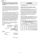
...3 Brush 1 Frame 1 Power Cord 1 Cord Clamp 4 Rack 1 Spring Pin Ø5 X 14 2 Spring Washer M6 3 Soc. I .D. Bolt M6*1.0-10 1 327546 0048 Flat Washer M6 1 327547 0049 Shaft 1 327548 0050 Link 1 327549 0051 Bracket 1 327550 0052 Soc. Description Size Qty 327530 0032 Upper Guide... Plate 1 Hex Hd. Bolt M8*1.25-20 4 327543 0045 Hinge Pivot 1 327544 0046 Sleeve 1 327545 0047 Soc. NUMBER. PARTS LIST 10″ Band Saw ALWAYS ORDER BY PART NO. Hd. Bolt M5*0.8-8 2 327551 0053 Tension Rod 1 327552 0054 Tension Nut 1 327553 0055 Idler Wheel Ass'y...
...3 Brush 1 Frame 1 Power Cord 1 Cord Clamp 4 Rack 1 Spring Pin Ø5 X 14 2 Spring Washer M6 3 Soc. I .D. Bolt M6*1.0-10 1 327546 0048 Flat Washer M6 1 327547 0049 Shaft 1 327548 0050 Link 1 327549 0051 Bracket 1 327550 0052 Soc. Description Size Qty 327530 0032 Upper Guide... Plate 1 Hex Hd. Bolt M8*1.25-20 4 327543 0045 Hinge Pivot 1 327544 0046 Sleeve 1 327545 0047 Soc. NUMBER. PARTS LIST 10″ Band Saw ALWAYS ORDER BY PART NO. Hd. Bolt M5*0.8-8 2 327551 0053 Tension Rod 1 327552 0054 Tension Nut 1 327553 0055 Idler Wheel Ass'y...

Instruction Manual
Page 59
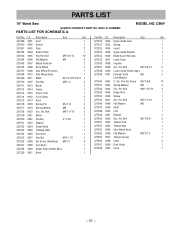
PARTS LIST 10″ Band Saw ALWAYS ORDER BY PART NO. Bolt Hex Hd....Handle Table Table Insert Table Locking Insert Wing Bolt Miter Gauge Ass'y Flat Washer Flat Washer Size Qty 1 M5 1 1 M8 4 1 1 M5*0.8-10 2 1 1 1 1 M6*1.0-20 1 1 M6*16*1.5 1 M12 1 - 59 - NUMBER PARTS LIST FOR SCHEMATIC B MODEL NO. Hd.... AND I .D. 0001 0002 0003 0004 0005 0006 0007 0008 0009 0010 0011 0012 0013 0014 0015 Description Head Mounting Bracket Base Plate Pointer Ass'y Flat Washer Soc. Hd. Bolt Spring Washer Spring Pin Size Qty 1 2 1 M5 2 M5*0.8-12...
PARTS LIST 10″ Band Saw ALWAYS ORDER BY PART NO. Bolt Hex Hd....Handle Table Table Insert Table Locking Insert Wing Bolt Miter Gauge Ass'y Flat Washer Flat Washer Size Qty 1 M5 1 1 M8 4 1 1 M5*0.8-10 2 1 1 1 1 M6*1.0-20 1 1 M6*16*1.5 1 M12 1 - 59 - NUMBER PARTS LIST FOR SCHEMATIC B MODEL NO. Hd.... AND I .D. 0001 0002 0003 0004 0005 0006 0007 0008 0009 0010 0011 0012 0013 0014 0015 Description Head Mounting Bracket Base Plate Pointer Ass'y Flat Washer Soc. Hd. Bolt Spring Washer Spring Pin Size Qty 1 2 1 M5 2 M5*0.8-12...
Parts List
Page 2
...0037 Lamp Cover 1 327536 0038 Impeller 1 327537 0039 Soc. Bolt M8*1.25-20 4 327543 0045 Hinge Pivot 1 327544 0046 Sleeve 1 327545 0047 Soc. PARTS LIST 10″ Band Saw ALWAYS ORDER BY PART NO. Re. Screw M5*0.8-8 13 327541 0043 Spring Washer M8 4 327542 0044 Soc. Bolt M6...*1.0-10 1 327546 0048 Flat Washer M6 1 327547 0049 Shaft 1 327548 0050 Link 1 327549 0051 Bracket 1 327550 0052 Soc. NUMBER. Bolt M5*0.8-12 16 Flat Washer M5 5...
...0037 Lamp Cover 1 327536 0038 Impeller 1 327537 0039 Soc. Bolt M8*1.25-20 4 327543 0045 Hinge Pivot 1 327544 0046 Sleeve 1 327545 0047 Soc. PARTS LIST 10″ Band Saw ALWAYS ORDER BY PART NO. Re. Screw M5*0.8-8 13 327541 0043 Spring Washer M8 4 327542 0044 Soc. Bolt M6...*1.0-10 1 327546 0048 Flat Washer M6 1 327547 0049 Shaft 1 327548 0050 Link 1 327549 0051 Bracket 1 327550 0052 Soc. NUMBER. Bolt M5*0.8-12 16 Flat Washer M5 5...

Parts List
Page 4
PARTS LIST 10″ Band Saw ALWAYS ORDER BY PART NO. Hd. CB6Y Part No. 327559 327560 327561... AND I .D. 0001 0002 0003 0004 0005 0006 0007 0008 0009 0010 0011 0012 0013 0014 0015 Description Head Mounting Bracket Base Plate Pointer Ass'y Flat Washer Soc. Bolt Crank Handle Table Table Insert Table Locking Insert... Wing Bolt Miter Gauge Ass'y Flat Washer Flat Washer Size Qty 1 M5 1 1 M8 4 1 1 M5*0.8-10 2 1 1 1 1 M6*1.0-20 1 1 M6*16*1.5 1 M12 1 - 59 - NUMBER PARTS LIST FOR SCHEMATIC B MODEL NO. Bolt Spring Washer ...
PARTS LIST 10″ Band Saw ALWAYS ORDER BY PART NO. Hd. CB6Y Part No. 327559 327560 327561... AND I .D. 0001 0002 0003 0004 0005 0006 0007 0008 0009 0010 0011 0012 0013 0014 0015 Description Head Mounting Bracket Base Plate Pointer Ass'y Flat Washer Soc. Bolt Crank Handle Table Table Insert Table Locking Insert... Wing Bolt Miter Gauge Ass'y Flat Washer Flat Washer Size Qty 1 M5 1 1 M8 4 1 1 M5*0.8-10 2 1 1 1 1 M6*1.0-20 1 1 M6*16*1.5 1 M12 1 - 59 - NUMBER PARTS LIST FOR SCHEMATIC B MODEL NO. Bolt Spring Washer ...


