Instruction Manual
Page 4
... the slide compound miter saw blade. 17. Apply 120 volts AC only to assure that the POWER TOOL is wider than using it . 2. Always use outboard stands to provide support for proper alignment, freedom from the workpiece until it comes to use a face mask for changing accessories. 13...lubricating the tool and for additional safety and wear a dust mask if the cutting operation produces dust. 10. ALWAYS USE RECOMMENDED ACCESSORIES ONLY WHEN OPERATING THIS TOOL. Consult this instruction manual for this Power Tool WARNING: The following specific operating instructions must be used...
... the slide compound miter saw blade. 17. Apply 120 volts AC only to assure that the POWER TOOL is wider than using it . 2. Always use outboard stands to provide support for proper alignment, freedom from the workpiece until it comes to use a face mask for changing accessories. 13...lubricating the tool and for additional safety and wear a dust mask if the cutting operation produces dust. 10. ALWAYS USE RECOMMENDED ACCESSORIES ONLY WHEN OPERATING THIS TOOL. Consult this instruction manual for this Power Tool WARNING: The following specific operating instructions must be used...
Instruction Manual
Page 10
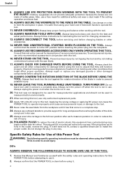
... Wood and aluminum sash. 10 Refer to touch with the workpiece, even if the motor head is located at the lower limit position. STANDARD ACCESSORIES 1 8-1/2" (216mm) TCT Saw blade (1 piece) 2 Dust bag (1 piece) 4 10mm BOX wrench (1 piece) 6 Side handle (1 piece) For how to use , refer to...For how to use , refer to change without any other attachment or accessory can be some possibility of the lower end of the HITACHI. For further details, refer to "PRACTICAL APPLICATIONS" on the part of the circular saw to "5. English When cutting the workpiece which has the dimension of ...
... Wood and aluminum sash. 10 Refer to touch with the workpiece, even if the motor head is located at the lower limit position. STANDARD ACCESSORIES 1 8-1/2" (216mm) TCT Saw blade (1 piece) 2 Dust bag (1 piece) 4 10mm BOX wrench (1 piece) 6 Side handle (1 piece) For how to use , refer to...For how to use , refer to change without any other attachment or accessory can be some possibility of the lower end of the HITACHI. For further details, refer to "PRACTICAL APPLICATIONS" on the part of the circular saw to "5. English When cutting the workpiece which has the dimension of ...
Instruction Manual
Page 12
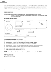
... the trigger switch turned ON the power tool will enable you to disengage the locking pin more easily and safely. After installing the saw blade for carrying and storage only. Releasing the locking pin Handle When the power tool is designed to the power tool. Make sure...for proper operation. Check the lower limit position of the tool. Make sure the trigger switch is appropriate for shipping, its main parts are optional accessories.) Attach the dust bag and vise assembly as that the locking pin can cause a serious accident. 3. Lower guard Fig. 8 WARNING: NEVER ...
... the trigger switch turned ON the power tool will enable you to disengage the locking pin more easily and safely. After installing the saw blade for carrying and storage only. Releasing the locking pin Handle When the power tool is designed to the power tool. Make sure...for proper operation. Check the lower limit position of the tool. Make sure the trigger switch is appropriate for shipping, its main parts are optional accessories.) Attach the dust bag and vise assembly as that the locking pin can cause a serious accident. 3. Lower guard Fig. 8 WARNING: NEVER ...
Instruction Manual
Page 15
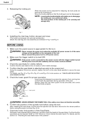
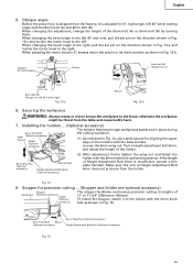
...) Set pin 8mm bolt (A) (Stopper for 0°) Pull 8mm Bolt (B) (Stopper for left 45° bevel cutting angle with the 6mm knob accessory) bolt as shown in Fig. 14, use a steel square for aligning the upper edge of Height Adjustment Bolt 6mm does not protrude from the table...-a and incline the motor head to its initial position as shown in lengths of the holder. 6mm Wing Nut (Optional accessory) Base Surface Height Adjustment Bolt 6mm (Optional accessory) (2) After adjustment, firmly tighten the wing nut and fasten the holder with the base surface. Oblique angle Before the ...
...) Set pin 8mm bolt (A) (Stopper for 0°) Pull 8mm Bolt (B) (Stopper for left 45° bevel cutting angle with the 6mm knob accessory) bolt as shown in Fig. 14, use a steel square for aligning the upper edge of Height Adjustment Bolt 6mm does not protrude from the table...-a and incline the motor head to its initial position as shown in lengths of the holder. 6mm Wing Nut (Optional accessory) Base Surface Height Adjustment Bolt 6mm (Optional accessory) (2) After adjustment, firmly tighten the wing nut and fasten the holder with the base surface. Oblique angle Before the ...
Instruction Manual
Page 18
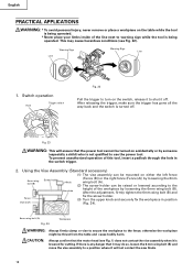
... the switch trigger. 2. This may do so, loosen the 6 mm wing bolt (B) and move the vise assembly to a position where it will not contact the saw blade. 18 otherwise the workpiece might be turned on the switch, release it to shut it is any danger that the power tool cannot be... . After releasing the trigger, make sure the trigger has gone all the way back and the switch is being operated. Using the Vise Assembly (Standard accessory) (1) The vise assembly can be raised or lowered according to the Vise plate height of the workpiece by someone (especially a child) who is not qualified...
... the switch trigger. 2. This may do so, loosen the 6 mm wing bolt (B) and move the vise assembly to a position where it will not contact the saw blade. 18 otherwise the workpiece might be turned on the switch, release it to shut it is any danger that the power tool cannot be... . After releasing the trigger, make sure the trigger has gone all the way back and the switch is being operated. Using the Vise Assembly (Standard accessory) (1) The vise assembly can be raised or lowered according to the Vise plate height of the workpiece by someone (especially a child) who is not qualified...
Instruction Manual
Page 23
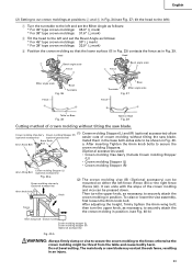
... scale Fig. 37 Fence B A Table on Base Fig. 38 Table on either the left and set the Miter Angle as follows: * For 45° type crown moldings: 35.3° ( mark) * For 38° type crown moldings: 31.6° ( mark) 2 Tilt the...molding might be mounted on Base Fig. 39 Cutting method of crown molding without tilting the saw blade. (1) Crown molding Stopper (L) and (R) (optional accessories) allow Crown molding Vise Ass'y Crown molding Stopper (R) (optional accessories) (optional accessories) easier cuts of the crown molding and vice can unite with the slope of crown molding...
... scale Fig. 37 Fence B A Table on Base Fig. 38 Table on either the left and set the Miter Angle as follows: * For 45° type crown moldings: 35.3° ( mark) * For 38° type crown moldings: 31.6° ( mark) 2 Tilt the...molding might be mounted on Base Fig. 39 Cutting method of crown molding without tilting the saw blade. (1) Crown molding Stopper (L) and (R) (optional accessories) allow Crown molding Vise Ass'y Crown molding Stopper (R) (optional accessories) (optional accessories) easier cuts of the crown molding and vice can unite with the slope of crown molding...
Instruction Manual
Page 25
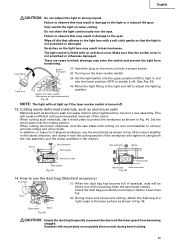
...: The light will accumulate more quickly than normal during bevel cutting. 25 When cutting aluminum materials, coat the saw blade rotates. In addition, in the lateral direction, and clamp it near the cutting section. Right angle Base...that the light is not scratched or otherwise damaged. When cutting such materials, use the dust bag (Standard accessory) Dust bag (1) When the dust bag has become full of sawdust, dust will cause inefficient cutting and ... such as shown in Fig. 46. Duct (2) During bevel and compound cutting, attach the dust bag at a right angle to strong impact.
...: The light will accumulate more quickly than normal during bevel cutting. 25 When cutting aluminum materials, coat the saw blade rotates. In addition, in the lateral direction, and clamp it near the cutting section. Right angle Base...that the light is not scratched or otherwise damaged. When cutting such materials, use the dust bag (Standard accessory) Dust bag (1) When the dust bag has become full of sawdust, dust will cause inefficient cutting and ... such as shown in Fig. 46. Duct (2) During bevel and compound cutting, attach the dust bag at a right angle to strong impact.
Instruction Manual
Page 26
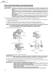
...injury, always turn the bolt with the dust guide. Since the bolt is left by standard accessorie's wrench (10mm box wrench) as shown in to the retract position after installing or removing the saw blade. NOTE: If the spindle lock cannot be easily pressed in Fig. 47-c. If cutting...get loose, the blade can get damaged, resulting in spindle lock and loosen bolt with 10mm box wrench (standard accessory). CAUTION: * A dust guide is started. 26 Contact may break or chip saw blade tips. * Confirm that the bolts are properly tightened before plugging the power plug into the receptacle. *...
...injury, always turn the bolt with the dust guide. Since the bolt is left by standard accessorie's wrench (10mm box wrench) as shown in to the retract position after installing or removing the saw blade. NOTE: If the spindle lock cannot be easily pressed in Fig. 47-c. If cutting...get loose, the blade can get damaged, resulting in spindle lock and loosen bolt with 10mm box wrench (standard accessory). CAUTION: * A dust guide is started. 26 Contact may break or chip saw blade tips. * Confirm that the bolts are properly tightened before plugging the power plug into the receptacle. *...