Instruction Manual
Page 4
... tool against the rotation direction of safety glass. This tool was not designed to a complete stop . 24. Never raise the saw blade from binding and other components for mass-production applications and should not be used in order to reduce the risk of recommended accessories... and familiarize yourself with this equipment has a polarized plug (one way. Always use outboard stands to provide support for Use of the slide compound miter saw blade. 17. Always confirm that might affect proper operation. Always keep tools sharp and clean for this POWER TOOL before using the tool...
... tool against the rotation direction of safety glass. This tool was not designed to a complete stop . 24. Never raise the saw blade from binding and other components for mass-production applications and should not be used in order to reduce the risk of recommended accessories... and familiarize yourself with this equipment has a polarized plug (one way. Always use outboard stands to provide support for Use of the slide compound miter saw blade. 17. Always confirm that might affect proper operation. Always keep tools sharp and clean for this POWER TOOL before using the tool...
Instruction Manual
Page 5
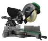
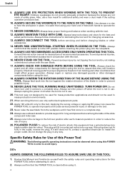
...your hair is in this tool. 8. use the POWER TOOL for the tool to completely stop completely before attempting slide cutting. 18. Always cease operating the saw blade with steel toes) and eye protection when operating the POWER TOOL. 4. Hold the tool firmly when in the...cause bodily harm. 11. Never operate the POWER TOOL when you fully understand the operating instructions contained in use of the slide compound miter saw is uncovered, to stop rotating before using the tool. 7. Never use of oil and grease. Never remove any alcoholic beverages. 4....
...your hair is in this tool. 8. use the POWER TOOL for the tool to completely stop completely before attempting slide cutting. 18. Always cease operating the saw blade with steel toes) and eye protection when operating the POWER TOOL. 4. Hold the tool firmly when in the...cause bodily harm. 11. Never operate the POWER TOOL when you fully understand the operating instructions contained in use of the slide compound miter saw is uncovered, to stop rotating before using the tool. 7. Never use of oil and grease. Never remove any alcoholic beverages. 4....
Instruction Manual
Page 6
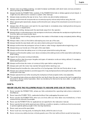
...Repairs should be conducted only by a Hitachi authorized service center. 6 Never use the POWER TOOL if the plastic housing or the handle is being operated. Never operate the saw . 5. Always disconnect power before using the slide compound miter saw blade. 6. To reduce the risk of... parts. Never use in place. 4. Never reach around the saw . 2. WARNING FOR YOUR OWN SAFETY READ THIS INSTRUCTION MANUAL BEFORE OPERATING THE SLIDE COMPOUND MITER SAW 1. Never clean plastic components with the slide compound miter saw without the guards in damp locations. 22. Always wear eye ...
...Repairs should be conducted only by a Hitachi authorized service center. 6 Never use the POWER TOOL if the plastic housing or the handle is being operated. Never operate the saw . 5. Always disconnect power before using the slide compound miter saw blade. 6. To reduce the risk of... parts. Never use in place. 4. Never reach around the saw . 2. WARNING FOR YOUR OWN SAFETY READ THIS INSTRUCTION MANUAL BEFORE OPERATING THE SLIDE COMPOUND MITER SAW 1. Never clean plastic components with the slide compound miter saw without the guards in damp locations. 22. Always wear eye ...
Instruction Manual
Page 8
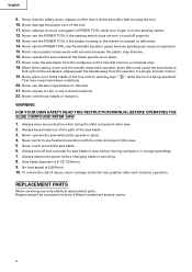
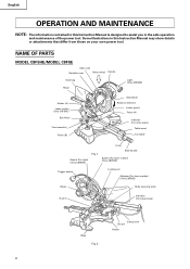
... on your own power tool. NAME OF PARTS MODEL C8FSHE/MODEL C8FSE Gear case Spindle cover Motor head Handle Dust bag Hinge Light (Only C8FSHE) ...Holder (A) Laser marker (Only C8FSHE) Sub fence Vise assembly Fence (B) Saw blade Rotation direction Lower guard Fence (A) Indicator (For miter scale) Table insert Turntable Lever Switch (For light) (Only C8FSHE) Fig.... 1 Side handle Switch (For laser marker) (Only C8FSHE) Trigger switch Locking pin Adjuster (For laser marker) (Only C8FSHE) Motor Slide...
... on your own power tool. NAME OF PARTS MODEL C8FSHE/MODEL C8FSE Gear case Spindle cover Motor head Handle Dust bag Hinge Light (Only C8FSHE) ...Holder (A) Laser marker (Only C8FSHE) Sub fence Vise assembly Fence (B) Saw blade Rotation direction Lower guard Fence (A) Indicator (For miter scale) Table insert Turntable Lever Switch (For light) (Only C8FSHE) Fig.... 1 Side handle Switch (For laser marker) (Only C8FSHE) Trigger switch Locking pin Adjuster (For laser marker) (Only C8FSHE) Motor Slide...
Instruction Manual
Page 9
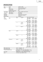
English SPECIFICATIONS Item Model C8FSHE / C8FSE Motor Type Series commutator motor Power source Single-phase AC 60Hz Voltage (Volts) 120 Full-load current (Amp) 9.2 Laser Marker Maximum output
English SPECIFICATIONS Item Model C8FSHE / C8FSE Motor Type Series commutator motor Power source Single-phase AC 60Hz Voltage (Volts) 120 Full-load current (Amp) 9.2 Laser Marker Maximum output
Instruction Manual
Page 21
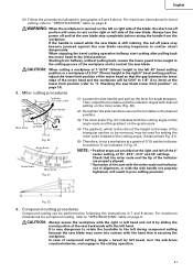
... of 1-15/16" (50mm) height in the left or right side of the blade, the short cut it by sliding the round portion of the saw blade. Checking the saw with the miter scale and indicator out of the motor head and the workpiece will come into contact with the hand that the... back, causes the lower guard to be 5/64" to 1/8" (2 to 3mm) at 15°, 22.5°, 31.6° and 45° settings. Compound cutting procedures Compound cutting can be used for angle stoppers. For maximum dimensions for bevel cutting, refer to "2. When stopping the bevel cutting operation halfway, start cutting...
... of 1-15/16" (50mm) height in the left or right side of the blade, the short cut it by sliding the round portion of the saw blade. Checking the saw with the miter scale and indicator out of the motor head and the workpiece will come into contact with the hand that the... back, causes the lower guard to be 5/64" to 1/8" (2 to 3mm) at 15°, 22.5°, 31.6° and 45° settings. Compound cutting procedures Compound cutting can be used for angle stoppers. For maximum dimensions for bevel cutting, refer to "2. When stopping the bevel cutting operation halfway, start cutting...
Instruction Manual
Page 23
... cutting. then turn the upper knob, as necessary, to securely attach the the crown molding in position. (see Fig. 37; The main body or saw blade. (1) Crown molding Stopper (L) and (R) (optional accessories) allow Crown molding Vise Ass'y Crown molding Stopper (R) (optional accessories) (optional accessories) easier... both-sides side to securely attach the crown molding in Fig. 39. After inserting Tighten the 6mm knob bolts to the left and set the Miter Angle as follows: * For 45° type crown moldings: 35.3° ( mark) * For 38° type crown moldings: 31.6° ( mark...
... cutting. then turn the upper knob, as necessary, to securely attach the the crown molding in position. (see Fig. 37; The main body or saw blade. (1) Crown molding Stopper (L) and (R) (optional accessories) allow Crown molding Vise Ass'y Crown molding Stopper (R) (optional accessories) (optional accessories) easier... both-sides side to securely attach the crown molding in Fig. 39. After inserting Tighten the 6mm knob bolts to the left and set the Miter Angle as follows: * For 45° type crown moldings: 35.3° ( mark) * For 38° type crown moldings: 31.6° ( mark...
Instruction Manual
Page 24
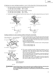
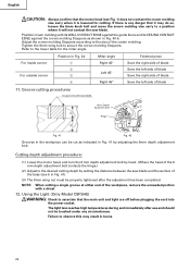
... is lowered for the miter angle. Cutting depth adjustment procedure: (1) Lower the motor head, and turn the 6 mm depth adjustment bolt by hand. (Where the head of the 6 mm depth adjustment bolt contacts the hinge.) (2) Adjust to a position where it will not contact the saw blade 6mm Depth adjustment bolt...(Only Model C8FSHE) WARNING: Check to the lower table for cutting. English CAUTION: Always confirm that the motor head (see b in Fig. 34 1 2 3 4 Miter angle Right 45° Left 45° Right 45° Finished piece Save the right side of blade Save the left side of blade Save...
... is lowered for the miter angle. Cutting depth adjustment procedure: (1) Lower the motor head, and turn the 6 mm depth adjustment bolt by hand. (Where the head of the 6 mm depth adjustment bolt contacts the hinge.) (2) Adjust to a position where it will not contact the saw blade 6mm Depth adjustment bolt...(Only Model C8FSHE) WARNING: Check to the lower table for cutting. English CAUTION: Always confirm that the motor head (see b in Fig. 34 1 2 3 4 Miter angle Right 45° Left 45° Right 45° Finished piece Save the right side of blade Save the left side of blade Save...


