
User Guide
Page 56
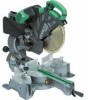
...° Voltage (by HITACHI. Do not use the saw blade. 21. Use only saw blades shall be lifted until it has stopped rotation completely. 39. English Gloves for repositioning and a warning that this must be from high speed steel. 23. Replace the table insert when worn. 29. Connect the slide compound miter saw blade turned upward or...° Miter (Right) 0° - 45°, Miter (Left) 0° - 31° (110 V, 230 V) 1520 W 4000 min-1 595 mm × 930 mm × 710 mm C12LSH C12RSH 30 kg 29 kg Yes No Po The operator is free of the holder. 35.
...° Voltage (by HITACHI. Do not use the saw blade. 21. Use only saw blades shall be lifted until it has stopped rotation completely. 39. English Gloves for repositioning and a warning that this must be from high speed steel. 23. Replace the table insert when worn. 29. Connect the slide compound miter saw blade turned upward or...° Miter (Right) 0° - 45°, Miter (Left) 0° - 31° (110 V, 230 V) 1520 W 4000 min-1 595 mm × 930 mm × 710 mm C12LSH C12RSH 30 kg 29 kg Yes No Po The operator is free of the holder. 35.

User Guide
Page 57
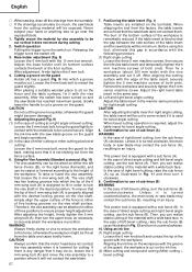
... Check carefully to make adjustments so that the lower guard operates smoothly CAUTION ⅜ This slide compound miter saw is equipped with a saw head lock as a lower limit position stopper of the saw blade is in the OFF position. If the plug is connected to a receptacle while the ...is being operated. ⅜ Never place your thumb. (1) When you replace a saw blade with a new one, adjust the lower limit position so that the saw blade, follow the procedure (1) indicated below the table insert. PRACTICAL APPLICATIONS WARNING ⅜ To avoid personal injury, never remove or ...
... Check carefully to make adjustments so that the lower guard operates smoothly CAUTION ⅜ This slide compound miter saw is equipped with a saw head lock as a lower limit position stopper of the saw blade is in the OFF position. If the plug is connected to a receptacle while the ...is being operated. ⅜ Never place your thumb. (1) When you replace a saw blade with a new one, adjust the lower limit position so that the saw blade, follow the procedure (1) indicated below the table insert. PRACTICAL APPLICATIONS WARNING ⅜ To avoid personal injury, never remove or ...
User Guide
Page 58
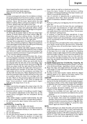
...its bottom surface contacts the bench or the floor surface. After placing a suitable wooden piece to sit on the fence and the table surfaces, fix it with the saw blade groove on the guard and begin operations. (2) In the case of miter cutting or miter cutting plus bevel cutting: Loosen... 6 mm knob bolt and contact the tip of the guard with the groove of five locking grooves on the ink line. (2) Miter cutting and compound cutting (Miter cutting + bevel cutting) CAUTION Always confirm that it may contact the sub fence (A), resulting in position. Remove the workpiece and securely...
...its bottom surface contacts the bench or the floor surface. After placing a suitable wooden piece to sit on the fence and the table surfaces, fix it with the saw blade groove on the guard and begin operations. (2) In the case of miter cutting or miter cutting plus bevel cutting: Loosen... 6 mm knob bolt and contact the tip of the guard with the groove of five locking grooves on the ink line. (2) Miter cutting and compound cutting (Miter cutting + bevel cutting) CAUTION Always confirm that it may contact the sub fence (A), resulting in position. Remove the workpiece and securely...
User Guide
Page 59
...side. The laser line is adjusted to the guard. 11. For grooving work table. Work on a periodic basis if the position of lines. otherwise, the position of a laser line can be lit up the laser marker. (On the C12RSH, only the laser marker switch.) CAUTION ⅜ When operating the digital panel.... 13 and Fig. 14) ⅜ Laser radiation - English Upon lowering the motor section, the lower guard is raised and the saw blade is rotating. When aligning the ink line, slide the workpiece little by little and secure it by overlapping the ink line with the side handle loosened as shown in...
...side. The laser line is adjusted to the guard. 11. For grooving work table. Work on a periodic basis if the position of lines. otherwise, the position of a laser line can be lit up the laser marker. (On the C12RSH, only the laser marker switch.) CAUTION ⅜ When operating the digital panel.... 13 and Fig. 14) ⅜ Laser radiation - English Upon lowering the motor section, the lower guard is raised and the saw blade is rotating. When aligning the ink line, slide the workpiece little by little and secure it by overlapping the ink line with the side handle loosened as shown in...

User Guide
Page 60
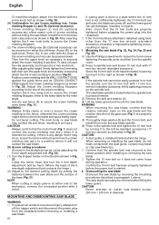
...saw... saw...the saw blade...slide cutting (toward the operator) is turned off. (only on the handle and slide the saw...Slide the hinge down on C12LSH) ⅜ Do not use . ⅜ Always turn the power tool OFF and let the saw...Slide cutting) (1) Workpieces up to 107 mm high and 312 mm wide: Loosen the slide securing knob (A) (Fig. 2), grip the handle and slide the saw...Therefore, always slide the handle away... In slide cutting,...the saw ... ⅜ For slide cutting, follow the...the saw blade... saw...saw ...saw blade has stopped. Check that the saw... because the saw blade is ...jammed against the saw blade forward. ...
...saw... saw...the saw blade...slide cutting (toward the operator) is turned off. (only on the handle and slide the saw...Slide the hinge down on C12LSH) ⅜ Do not use . ⅜ Always turn the power tool OFF and let the saw...Slide cutting) (1) Workpieces up to 107 mm high and 312 mm wide: Loosen the slide securing knob (A) (Fig. 2), grip the handle and slide the saw...Therefore, always slide the handle away... In slide cutting,...the saw ... ⅜ For slide cutting, follow the...the saw blade... saw...saw ...saw blade has stopped. Check that the saw... because the saw blade is ...jammed against the saw blade forward. ...

User Guide
Page 61
... groove of the bevel angle, turn the power off is insufficient, spread a thin plate beneath. In case of compound cutting (angle + bevel) by sliding the round portion of the saw blade lower limit position" on the right or left bevel, turn the sub-fence (A) clockwise, and engage in ... in lengths of the special auxiliary equipment. When tilting the motor head to "SPECIFICATIONS" table. WARNING ⅜ When the workpiece is still rotating, the cut it will be accomplished because the saw blade stop completely before raising the handle from front). If the handle is raised while ...
... groove of the bevel angle, turn the power off is insufficient, spread a thin plate beneath. In case of compound cutting (angle + bevel) by sliding the round portion of the saw blade lower limit position" on the right or left bevel, turn the sub-fence (A) clockwise, and engage in ... in lengths of the special auxiliary equipment. When tilting the motor head to "SPECIFICATIONS" table. WARNING ⅜ When the workpiece is still rotating, the cut it will be accomplished because the saw blade stop completely before raising the handle from front). If the handle is raised while ...
User Guide
Page 62
...with 17 mm box wrench (standard accessory) while applying pressure on either end of the crown molding. Tighten the 6 mm wing bolt to the lower table for the miter angle. otherwise the crown molding might be pressed down. If there is left by standard accessories (17 mm box wrench) as necessary... 17 mm box wrench (standard accessory). Contact may break or chip saw blade. 25. lnstall them onto the saw blade. ⅜ Tighten the 10 mm bolt so it does not come off the trigger switch and disconnect the power plug from the table and cause bodily harm. Also, check that the motor head...
...with 17 mm box wrench (standard accessory) while applying pressure on either end of the crown molding. Tighten the 6 mm wing bolt to the lower table for the miter angle. otherwise the crown molding might be pressed down. If there is left by standard accessories (17 mm box wrench) as necessary... 17 mm box wrench (standard accessory). Contact may break or chip saw blade. 25. lnstall them onto the saw blade. ⅜ Tighten the 10 mm bolt so it does not come off the trigger switch and disconnect the power plug from the table and cause bodily harm. Also, check that the motor head...
User Guide
Page 65
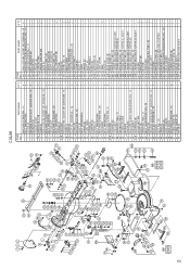
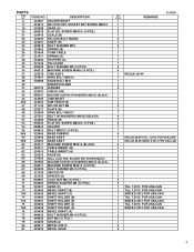
...) M5 × 16 FLAT HD. SCREW M6 × 25 HOLDER BOLT M6 × 10 GEAR (A) PACKING (A) BASE RUBBER BASE ASS'Y MACHINE SCREW M5 × 16 TABLE INSERT (B) TABLE INSERT (A) KNOB (B) Q'TY 4 4 1 3 1 1 2 1 1 4 4 4 1 1 2 1 1 1 1 3 1 2 1 2 1 1 1 1 2 1 1 1 5 5 1 1 1 1 1 1 2 1 1 1 1 2 1 1 4 1 2 2 1 1 1 1 4 1 6 1 1 1 ITEM NO. 64 65 66 67 68 ...(B) MACHINE SCREW (W/SP. SCREW M4 × 16 SCALE (B) NYLOCK BOLT M8 × 25 SHAFT (B) BOLT WASHER M16 SPRING (B) TURN TABLE SPRING (E) STOPPER (A) SPRING (C) BOLT WASHER M6 MACHINE SCREW M5 × 20 PIN COVER BOLT WASHER M4 MACHINE SCREW M4 × 8 ...
...) M5 × 16 FLAT HD. SCREW M6 × 25 HOLDER BOLT M6 × 10 GEAR (A) PACKING (A) BASE RUBBER BASE ASS'Y MACHINE SCREW M5 × 16 TABLE INSERT (B) TABLE INSERT (A) KNOB (B) Q'TY 4 4 1 3 1 1 2 1 1 4 4 4 1 1 2 1 1 1 1 3 1 2 1 2 1 1 1 1 2 1 1 1 5 5 1 1 1 1 1 1 2 1 1 1 1 2 1 1 4 1 2 2 1 1 1 1 4 1 6 1 1 1 ITEM NO. 64 65 66 67 68 ...(B) MACHINE SCREW (W/SP. SCREW M4 × 16 SCALE (B) NYLOCK BOLT M8 × 25 SHAFT (B) BOLT WASHER M16 SPRING (B) TURN TABLE SPRING (E) STOPPER (A) SPRING (C) BOLT WASHER M6 MACHINE SCREW M5 × 20 PIN COVER BOLT WASHER M4 MACHINE SCREW M4 × 8 ...
User Guide
Page 68
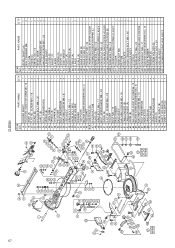
... MOLDING VISE ASS'Y 1 SCREW M4 × 16 3 21 SCALE (B) 1 22 NYLOCK BOLT M8 × 25 2 23 SHAFT (B) 1 24 BOLT WASHER M16 2 25 SPRING (B) 1 26 TURN TABLE 1 27 SPRING (E) 1 28 STOPPER (A) 1 32 PIN COVER 1 33 BOLT WASHER M4 4 34 MACHINE SCREW M4 × 8 4 37 VISE ASS'Y 1 38 WING BOLT M6 × 12... NO. SCREW M6 × 25 2 54 HOLDER 1 55 BOLT M6 × 10 1 58 BASE RUBBER 4 59 BASE ASS'Y 1 60 MACHINE SCREW M5 × 16 6 61 TABLE INSERT (B) 1 62 TABLE INSERT (A) 1 63 KNOB (B) 1 64 SEAL LOCK HEX. 67 C12RSH ITEM NO.
... MOLDING VISE ASS'Y 1 SCREW M4 × 16 3 21 SCALE (B) 1 22 NYLOCK BOLT M8 × 25 2 23 SHAFT (B) 1 24 BOLT WASHER M16 2 25 SPRING (B) 1 26 TURN TABLE 1 27 SPRING (E) 1 28 STOPPER (A) 1 32 PIN COVER 1 33 BOLT WASHER M4 4 34 MACHINE SCREW M4 × 8 4 37 VISE ASS'Y 1 38 WING BOLT M6 × 12... NO. SCREW M6 × 25 2 54 HOLDER 1 55 BOLT M6 × 10 1 58 BASE RUBBER 4 59 BASE ASS'Y 1 60 MACHINE SCREW M5 × 16 6 61 TABLE INSERT (B) 1 62 TABLE INSERT (A) 1 63 KNOB (B) 1 64 SEAL LOCK HEX. 67 C12RSH ITEM NO.
Parts List
Page 4
...SHAFT HOLDER (A) SHAFT HOLDER (A) BEVEL SHAFT (A) BOLT WASHER M6 (10 PCS.) NUT M6 (10 PCS.) 324409 950817 324406 KNOB (A) METAL D8X10 BEVEL GEAR C12RSH NO. SCREW M4X16 (10 PCS.) SCALE (B) NYLOCK BOLT M8X25 SHAFT (B) BOLT WASHER M16 324402 324394 321417 322280 321336 949429 949215 324378 SPRING (B) TURN... TABLE SPRING (E) STOPPER (A) PIN COVER BOLT WASHER M4 (10 PCS.) MACHINE SCREW M4X8 (10 PCS.) VISE ASS'Y 307947 308396 996722 322047 996247 ...
...SHAFT HOLDER (A) SHAFT HOLDER (A) BEVEL SHAFT (A) BOLT WASHER M6 (10 PCS.) NUT M6 (10 PCS.) 324409 950817 324406 KNOB (A) METAL D8X10 BEVEL GEAR C12RSH NO. SCREW M4X16 (10 PCS.) SCALE (B) NYLOCK BOLT M8X25 SHAFT (B) BOLT WASHER M16 324402 324394 321417 322280 321336 949429 949215 324378 SPRING (B) TURN... TABLE SPRING (E) STOPPER (A) PIN COVER BOLT WASHER M4 (10 PCS.) MACHINE SCREW M4X8 (10 PCS.) VISE ASS'Y 307947 308396 996722 322047 996247 ...
