

Instruction Manual
Page 5
... reverse the plug. ALWAYS MAINTAIN TOOLS WITH CARE. Always follow instructions for lubricating the tool and for descriptions of the slide compound miter saw blade from binding and other components for long workpieces that they will fit in mass-production environments. 21. NEVER RISK UNINTENTIONAL...15. Specific Safety Rules for Use of electric shock, this instruction manual for changing accessories. 13. Never raise the saw . 25. English 12. Always confirm that might affect proper operation. Always keep tools sharp and clean for mass-production applications and should not...
... reverse the plug. ALWAYS MAINTAIN TOOLS WITH CARE. Always follow instructions for lubricating the tool and for descriptions of the slide compound miter saw blade from binding and other components for long workpieces that they will fit in mass-production environments. 21. NEVER RISK UNINTENTIONAL...15. Specific Safety Rules for Use of electric shock, this instruction manual for changing accessories. 13. Never raise the saw . 25. English 12. Always confirm that might affect proper operation. Always keep tools sharp and clean for mass-production applications and should not...

Instruction Manual
Page 6
...guard is fixed properly with steel toes) and eye protection when operating the POWER TOOL. 4. When replacing the saw blade. 12. Always handle the saw blade away from the operator. 10. Always wait until the motor has reached full speed before using it might...attempting to provide support for long workpieces that the lower guard does not obstruct the sliding motion of the slide compound miter saw before doing any abnormality whatsoever. 6. During miter or bevel cutting, always wait for the saw at once, if you notice any maintenance or adjustments. 9. Always make a trial...
...guard is fixed properly with steel toes) and eye protection when operating the POWER TOOL. 4. When replacing the saw blade. 12. Always handle the saw blade away from the operator. 10. Always wait until the motor has reached full speed before using it might...attempting to provide support for long workpieces that the lower guard does not obstruct the sliding motion of the slide compound miter saw before doing any abnormality whatsoever. 6. During miter or bevel cutting, always wait for the saw at once, if you notice any maintenance or adjustments. 9. Always make a trial...

Instruction Manual
Page 7
...or changing settings. 7 always confirm that it has first come to kick up from the operator in this could cause the saw . 21. Never clean plastic components with the slide compound miter saw . 2. Always push the handle away from the workpiece. Never expose to move a plugged-in POWER TOOL while your finger... when you have taken any medications, or have consumed any safety devices or blade guards; Never use the POWER TOOL if the starting switch. 12. Never operate the tool while wearing loose clothing, a necktie or jewelry, or while your limbs inside of the tool. 11. Never touch ...
...or changing settings. 7 always confirm that it has first come to kick up from the operator in this could cause the saw . 21. Never clean plastic components with the slide compound miter saw . 2. Always push the handle away from the workpiece. Never expose to move a plugged-in POWER TOOL while your finger... when you have taken any medications, or have consumed any safety devices or blade guards; Never use the POWER TOOL if the starting switch. 12. Never operate the tool while wearing loose clothing, a necktie or jewelry, or while your limbs inside of the tool. 11. Never touch ...
Instruction Manual
Page 8
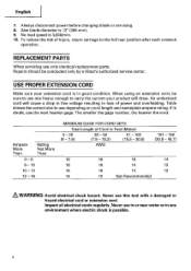
... gage. When using an extension cord, be conducted only by a Hitachi authorized service center. If in any environment where electric shock is 12" (305 mm). 9. Ampere More Than Rating Not More Than 0 - 6 6- 10 10 - 12 12 - 16 MINIMUM GAGE FOR CORD SETS Total Length of injury, return... cords regularly. English 7. USE PROPER EXTENSION CORD Make sure your product will cause a drop in line voltage resulting in good condition. Saw blade diameter is possible. 8 Table shows the correct size to carry the current your extension cord is 3,800/min. 10. Always disconnect...
... gage. When using an extension cord, be conducted only by a Hitachi authorized service center. If in any environment where electric shock is 12" (305 mm). 9. Ampere More Than Rating Not More Than 0 - 6 6- 10 10 - 12 12 - 16 MINIMUM GAGE FOR CORD SETS Total Length of injury, return... cords regularly. English 7. USE PROPER EXTENSION CORD Make sure your product will cause a drop in line voltage resulting in good condition. Saw blade diameter is possible. 8 Table shows the correct size to carry the current your extension cord is 3,800/min. 10. Always disconnect...

Instruction Manual
Page 10
... Digital display Motor Nameplate (only C12LSH) Gear case Motor head Dust bag Locking pin Handle Hinge Spindle cover Holder (A) Clamp lever Laser marker Knob (B) Indicator (For right bevel scale) Set pin (A) Sub fence (B) Vise assembly Fence (B) Base UlEI 11/ Fig. 1 Rotation direction 0 Indicator (For miter scale) Lower guard Saw blade Sub fence (A) Fence (A) Table...
... Digital display Motor Nameplate (only C12LSH) Gear case Motor head Dust bag Locking pin Handle Hinge Spindle cover Holder (A) Clamp lever Laser marker Knob (B) Indicator (For right bevel scale) Set pin (A) Sub fence (B) Vise assembly Fence (B) Base UlEI 11/ Fig. 1 Rotation direction 0 Indicator (For miter scale) Lower guard Saw blade Sub fence (A) Fence (A) Table...

Instruction Manual
Page 12
English SPECIFICATIONS Item Model C 12LSH /C 12RSH Motor Type Series commutator motor Power source Single-phase AC 60Hz Voltage (Volts) 120 Full-load current (Amp) 15 Laser Marker Maximum output
English SPECIFICATIONS Item Model C 12LSH /C 12RSH Motor Type Series commutator motor Power source Single-phase AC 60Hz Voltage (Volts) 120 Full-load current (Amp) 15 Laser Marker Maximum output
Instruction Manual
Page 13
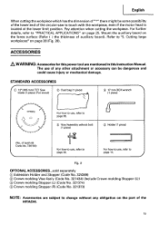
Refer to use of the HITACHI. 13 Mount the auxiliary board on page 25. of teeth 60 Code No. ...are subject to change without any other attachment or accessory can be some possibility of the lower end of the circular saw to "PRACTICAL APPLICATIONS" on the fence surface (Refer ( ) the thickness of auxiliary board). English When cutting ...part of any obligation on page 28 (Fig. 28). Pay attention when cutting the workpiece. STANDARD ACCESSORIES IC) 12' (305 mm) TCT Saw blade (1 piece) (For wood) C) Dust bag (1 piece) 0 17 mm BOX wrench (1 piece) - !/ 1-1 // n -...
Refer to use of the HITACHI. 13 Mount the auxiliary board on page 25. of teeth 60 Code No. ...are subject to change without any other attachment or accessory can be some possibility of the lower end of the circular saw to "PRACTICAL APPLICATIONS" on the fence surface (Refer ( ) the thickness of auxiliary board). English When cutting ...part of any obligation on page 28 (Fig. 28). Pay attention when cutting the workpiece. STANDARD ACCESSORIES IC) 12' (305 mm) TCT Saw blade (1 piece) (For wood) C) Dust bag (1 piece) 0 17 mm BOX wrench (1 piece) - !/ 1-1 // n -...
Instruction Manual
Page 15
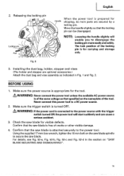
NOTE: Lowering the handle slightly will start suddenly and can be disengaged. BEFORE USING 1. Never connect this power tool to secure the saw blade. WARNING: If the power cord is of cracks or other visible damage. 4. Confirm that the locking pin can cause a serious accident. 3. Pull Handle... only. Make sure the trigger switch is for shipping, its main parts are optional accessories.) Attach the dust bag and vise assembly as that the saw blade spindle to a DC power source. 2. For details, see Fig. 52-a, Fig. 52-b, Fig. 52-c and Fig. 52-d in Fig. 1 and Fig. 2. English 2. ...
NOTE: Lowering the handle slightly will start suddenly and can be disengaged. BEFORE USING 1. Never connect this power tool to secure the saw blade. WARNING: If the power cord is of cracks or other visible damage. 4. Confirm that the locking pin can cause a serious accident. 3. Pull Handle... only. Make sure the trigger switch is for shipping, its main parts are optional accessories.) Attach the dust bag and vise assembly as that the saw blade spindle to a DC power source. 2. For details, see Fig. 52-a, Fig. 52-b, Fig. 52-c and Fig. 52-d in Fig. 1 and Fig. 2. English 2. ...
Instruction Manual
Page 16
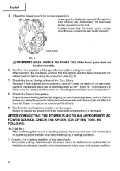
...fall out after it is not damaged. Trial Run After confirming that no operating abnormalities exist before shipment, carefully check the height of the Saw Blade. Repair or replace the receptacle if it is not noticeably unstable; English 5. Check the lower guard for deflection to the retract position... before using the power tool (see the section on "Checking the saw blade, confirm that no one is standing behind, the power tool start and confirm that the spindle lock has been returned to confirm that...
...fall out after it is not damaged. Trial Run After confirming that no operating abnormalities exist before shipment, carefully check the height of the Saw Blade. Repair or replace the receptacle if it is not noticeably unstable; English 5. Check the lower guard for deflection to the retract position... before using the power tool (see the section on "Checking the saw blade, confirm that no one is standing behind, the power tool start and confirm that the spindle lock has been returned to confirm that...
Instruction Manual
Page 17
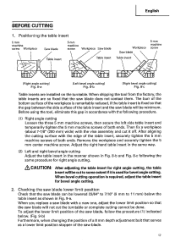
... ends. Remove the workpiece and securely tighten the 5 mm center machine screw. When bevel cutting operation is used for bevel angle cutting. 2. Positioning the table insert 5mm machine screw Workpiece Saw blade 5mm machine screw Workpiece Saw blade Table insert Table insert Workpiece Saw blade Table insert 5mm machine screw [Right angle cutting] Fig. 8-a [Left...
... ends. Remove the workpiece and securely tighten the 5 mm center machine screw. When bevel cutting operation is used for bevel angle cutting. 2. Positioning the table insert 5mm machine screw Workpiece Saw blade 5mm machine screw Workpiece Saw blade Table insert Table insert Workpiece Saw blade Table insert 5mm machine screw [Right angle cutting] Fig. 8-a [Left...
Instruction Manual
Page 18
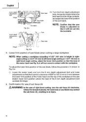
...the procedure (1) shown in Fig. 9-a. 0 Lower the motor head, and turn the sub fence (A) clockwise. Lower limit position of saw blade's lower limit position where the head of right bevel cutting, turn the 8 mm depth adjustment bolt and make adjustments so that there can be a clearance of 5/64" to 1/8" ...and the top of the workpiece at the saw blade when cutting a large workpiece NOTE: When cutting a workpiece exceeding 4-7/32" (107 mm) in height in rightangle cutting or 2-3/4"(70 mm) in left bevel angle cutting or 1-3/4" (45 mm) in right bevel angle cutting, adjust the lower limit position ...
...the procedure (1) shown in Fig. 9-a. 0 Lower the motor head, and turn the sub fence (A) clockwise. Lower limit position of saw blade's lower limit position where the head of right bevel cutting, turn the 8 mm depth adjustment bolt and make adjustments so that there can be a clearance of 5/64" to 1/8" ...and the top of the workpiece at the saw blade when cutting a large workpiece NOTE: When cutting a workpiece exceeding 4-7/32" (107 mm) in height in rightangle cutting or 2-3/4"(70 mm) in left bevel angle cutting or 1-3/4" (45 mm) in right bevel angle cutting, adjust the lower limit position ...
Instruction Manual
Page 19
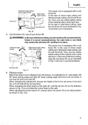
... Fig.11 and turn it clockwise. 5. Oblique angle Before the power tool is shipped from the factory, it is turned counterclockwise, the main body or saw blade may contact the sub fence (B), resulting in Fig. 10 and then turn the sub fence (B) counterclockwise. In the case of sub fence (B) &... the right. Unless it is adjusted for use of direct angle cutting and left 45° bevel cutting angle and right 45° bevel cutting angle with the 8 mm set pin (A) on the direction shown in Fig. 12-b. 19 Then, you can realize stable cutting of direct angle cutting and right...
... Fig.11 and turn it clockwise. 5. Oblique angle Before the power tool is shipped from the factory, it is turned counterclockwise, the main body or saw blade may contact the sub fence (B), resulting in Fig. 10 and then turn the sub fence (B) counterclockwise. In the case of sub fence (B) &... the right. Unless it is adjusted for use of direct angle cutting and left 45° bevel cutting angle and right 45° bevel cutting angle with the 8 mm set pin (A) on the direction shown in Fig. 12-b. 19 Then, you can realize stable cutting of direct angle cutting and right...
Instruction Manual
Page 21
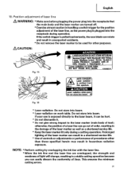
... not stare into beam. 43 Fig. 16 * Laser radiation- DO NOT STARE INTO BEAM. 0324601© Fig. 15 0 A AVOID EXPOSURE Laser radiation is pulledinadvertently,the saw blade can be hurt. * Do not dismantle it can rotate and result in a shortened service life. * Use of controls or adjustments or performance of laser...
... not stare into beam. 43 Fig. 16 * Laser radiation- DO NOT STARE INTO BEAM. 0324601© Fig. 15 0 A AVOID EXPOSURE Laser radiation is pulledinadvertently,the saw blade can be hurt. * Do not dismantle it can rotate and result in a shortened service life. * Use of controls or adjustments or performance of laser...
Instruction Manual
Page 22
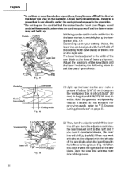
.... 17) Depending upon your cutting choice, the laser line can be easily made on this tool to the sunlight. Workpiece Marking (pre-marked) Fig. 17 Saw blade Cutting width Fig. 18 (1) Light up . English *In outdoor or near-the-window operations,itmay become difficult to observe the laser line due to...) in height and 5-29/32"(150 mm) in the operation. * Do not tug on the right side. Adjust the positions of the saw blade at the time of the saw blade) or the ink line 0 6 Laser line on the cord behind the motor head or hook your choice. Vise assembly Move---73...
.... 17) Depending upon your cutting choice, the laser line can be easily made on this tool to the sunlight. Workpiece Marking (pre-marked) Fig. 17 Saw blade Cutting width Fig. 18 (1) Light up . English *In outdoor or near-the-window operations,itmay become difficult to observe the laser line due to...) in height and 5-29/32"(150 mm) in the operation. * Do not tug on the right side. Adjust the positions of the saw blade at the time of the saw blade) or the ink line 0 6 Laser line on the cord behind the motor head or hook your choice. Vise assembly Move---73...
Instruction Manual
Page 26
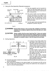
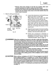
...does not contact the vise assembly whenit is lowered for cutting.If there is desired. Therefore, slide the workpiece to the right (viewed from the workpiece to return it will not contact the saw blade stop completely before raising the handle from the operator's 0 0 0 position) when length...align the ink line with the laser line. (Front view) (2) Once the saw blade reaches Fig. 26 maximum speed, push the handle down carefully until the saw blade approaches the workpiece. (3) Once the saw blade contacts the workpiece, push the handle down gradually to the full retract position...
...does not contact the vise assembly whenit is lowered for cutting.If there is desired. Therefore, slide the workpiece to the right (viewed from the workpiece to return it will not contact the saw blade stop completely before raising the handle from the operator's 0 0 0 position) when length...align the ink line with the laser line. (Front view) (2) Once the saw blade reaches Fig. 26 maximum speed, push the handle down carefully until the saw blade approaches the workpiece. (3) Once the saw blade contacts the workpiece, push the handle down gradually to the full retract position...
Instruction Manual
Page 27
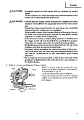
... about dangerously. * Every time one cutting or deep-cutting operation is not in use. * Always turn the trigger switch off and let the saw blade has stopped. t Press Lower the handle to the next step. * Continued cutting operation can result in Fig. 27. English &CAUTION: ...then proceed to cut material from the workpiece. Cutting narrow workpieces (Press cutting) Hinge Handle Slide the hinge down Using the power tool this could cause damage to holder (A), then tighten the slide securing knob (A)/(B) (see Fig. 2) as this way will not increase the cutting speed. ...
... about dangerously. * Every time one cutting or deep-cutting operation is not in use. * Always turn the trigger switch off and let the saw blade has stopped. t Press Lower the handle to the next step. * Continued cutting operation can result in Fig. 27. English &CAUTION: ...then proceed to cut material from the workpiece. Cutting narrow workpieces (Press cutting) Hinge Handle Slide the hinge down Using the power tool this could cause damage to holder (A), then tighten the slide securing knob (A)/(B) (see Fig. 2) as this way will not increase the cutting speed. ...
Instruction Manual
Page 28
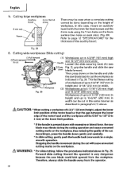
...(260 mm) in Fig. 29. Accordingly, press the handle down on the handle and slide the saw blade back to 3 mm) at the lower limit position. * If the handle is very dangerous because the saw blade could kick upward from the operator. 28 In this case, mount an auxiliary board ... cut in the same manner as described in height and up to 4-3/16" (107 mm) high and 12-1/4" (312 mm) wide: Handle Loosen the slide securing knob (A) (see t C) Press Fig. 2), grip the handle and slide the saw blade may be case when a complete cutting cannot be cut 4-- r," S Fig. 29 (1) Workpieces up...
...(260 mm) in Fig. 29. Accordingly, press the handle down on the handle and slide the saw blade back to 3 mm) at the lower limit position. * If the handle is very dangerous because the saw blade could kick upward from the operator. 28 In this case, mount an auxiliary board ... cut in the same manner as described in height and up to 4-3/16" (107 mm) high and 12-1/4" (312 mm) wide: Handle Loosen the slide securing knob (A) (see t C) Press Fig. 2), grip the handle and slide the saw blade may be case when a complete cutting cannot be cut 4-- r," S Fig. 29 (1) Workpieces up...
Instruction Manual
Page 29
... head so that the gap between the lower edge of the clamp lever. (2) Adjust the bevel angle to the side handle when the motor head is secured on page 12. When stopping the bevel cutting operation halfway, start cutting after each crosscut operation in order to reduce the risk of ...the workpiece and to contact the saw blade comes close to the desired setting while watching the bevel angle scale and indicator, then secure ...
... head so that the gap between the lower edge of the clamp lever. (2) Adjust the bevel angle to the side handle when the motor head is secured on page 12. When stopping the bevel cutting operation halfway, start cutting after each crosscut operation in order to reduce the risk of ...the workpiece and to contact the saw blade comes close to the desired setting while watching the bevel angle scale and indicator, then secure ...
Instruction Manual
Page 31
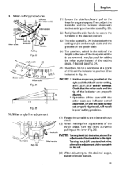
..., may be used for angle stoppers. b0 0 Grade scale -ob 1"I A0 O 12/ 1O j 0 3/1 1225 Miter scale Fig. 34 M 10 Fig. 35 (5) Therefore, to the miter angle you need. (2) When making fine adjustments of the miter angle, turn the knob (A) while pulling up the lever for setting the... at 15°, 22.5°, 31.6° and 45° settings. NOTE: * Positive stops are properly aligned. * Operation of the saw with the miter scale and indicator out of the cutting angle, if desired (see Fig. 34). Turning knob (A) counterclockwise, Fig. 36 allows fine adjustment of...
..., may be used for angle stoppers. b0 0 Grade scale -ob 1"I A0 O 12/ 1O j 0 3/1 1225 Miter scale Fig. 34 M 10 Fig. 35 (5) Therefore, to the miter angle you need. (2) When making fine adjustments of the miter angle, turn the knob (A) while pulling up the lever for setting the... at 15°, 22.5°, 31.6° and 45° settings. NOTE: * Positive stops are properly aligned. * Operation of the saw with the miter scale and indicator out of the cutting angle, if desired (see Fig. 34). Turning knob (A) counterclockwise, Fig. 36 allows fine adjustment of...
Instruction Manual
Page 32
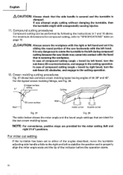
...rotate the turntable to the left and right 31.6°) positions. In case of compound cutting (angle + bevel) by left bevel, turn the sub-fence (A) clockwise, and engage in the cutting operation. 12. For the typical crown molding fittings, see Fig. 38. ® Upper ...miter angle scale and the tip of the angles described, move the turntable adjusting side handle a little to either of the indicator before the operation starts. 32 In case of (0) 38° and 45°. Compound cutting procedures Compound cutting can be performed by sliding the round portion of the saw...
...rotate the turntable to the left and right 31.6°) positions. In case of compound cutting (angle + bevel) by left bevel, turn the sub-fence (A) clockwise, and engage in the cutting operation. 12. For the typical crown molding fittings, see Fig. 38. ® Upper ...miter angle scale and the tip of the angles described, move the turntable adjusting side handle a little to either of the indicator before the operation starts. 32 In case of (0) 38° and 45°. Compound cutting procedures Compound cutting can be performed by sliding the round portion of the saw...


