Instruction Manual
Page 10
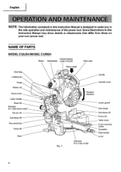
... C12RSH Digital display Motor Nameplate (only C12LSH) Gear case Motor head Dust bag Locking pin Handle Hinge Spindle cover Holder (A) Clamp lever Laser marker Knob (B) Indicator (For right bevel scale) Set pin (A) Sub fence (B) Vise assembly Fence (B) Base UlEI 11/ Fig. 1 Rotation direction 0 Indicator (For miter scale) Lower guard Saw blade Sub fence (A) Fence (A) Table...
... C12RSH Digital display Motor Nameplate (only C12LSH) Gear case Motor head Dust bag Locking pin Handle Hinge Spindle cover Holder (A) Clamp lever Laser marker Knob (B) Indicator (For right bevel scale) Set pin (A) Sub fence (B) Vise assembly Fence (B) Base UlEI 11/ Fig. 1 Rotation direction 0 Indicator (For miter scale) Lower guard Saw blade Sub fence (A) Fence (A) Table...
Instruction Manual
Page 12
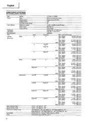
English SPECIFICATIONS Item Model C 12LSH /C 12RSH Motor Type Series commutator motor Power source Single-phase AC 60Hz Voltage (Volts) 120 Full-load current (Amp) 15 Laser Marker Maximum output
English SPECIFICATIONS Item Model C 12LSH /C 12RSH Motor Type Series commutator motor Power source Single-phase AC 60Hz Voltage (Volts) 120 Full-load current (Amp) 15 Laser Marker Maximum output
Instruction Manual
Page 21
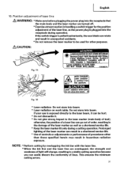
Do not stare into beam. Do not stare into beam. * Laser radiation on work table. Laser radiation on work table. If your eye is pulledinadvertently,the saw blade can rotate and result in a stable cutting operation because you can result in the damage of lines. NOTE: * Perform ...cutting by overlapping the ink line with 21 CFR, Chapter 1, Subchapter J. Position adjustment of laser line ,A WARNING: * Make sure ...
Do not stare into beam. Do not stare into beam. * Laser radiation on work table. Laser radiation on work table. If your eye is pulledinadvertently,the saw blade can rotate and result in a stable cutting operation because you can result in the damage of lines. NOTE: * Perform ...cutting by overlapping the ink line with 21 CFR, Chapter 1, Subchapter J. Position adjustment of laser line ,A WARNING: * Make sure ...
Instruction Manual
Page 22
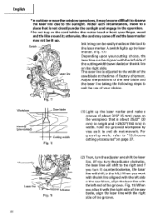
... on the workpiece that is adjusted to the left.) When you turn it with the right side of the saw blade, align the laser line with the left side of the cutting width (saw blade at the time of the groove. 22 Switch Ink lining can be aligned with the left end of... will shift to the right and if you work , refer to the sunlight. Workpiece Marking (pre-marked) Fig. 17 Saw blade Cutting width Fig. 18 (1) Light up the laser marker. (Fig. 17) Depending upon your choice. Hold the grooved workpiece by vise as it is about 3/16" (5 mm) deep on the cord...
... on the workpiece that is adjusted to the left.) When you turn it with the right side of the saw blade, align the laser line with the left side of the cutting width (saw blade at the time of the groove. 22 Switch Ink lining can be aligned with the left end of... will shift to the right and if you work , refer to the sunlight. Workpiece Marking (pre-marked) Fig. 17 Saw blade Cutting width Fig. 18 (1) Light up the laser marker. (Fig. 17) Depending upon your choice. Hold the grooved workpiece by vise as it is about 3/16" (5 mm) deep on the cord...
Instruction Manual
Page 23
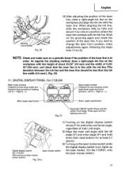
... display switch Laser marker switch (for C12LSH) (Also serves as laser marker power switch.) Fig. 22-a the laser marker. (On the C12RSH, only the laser marker switch.) 23 Left is on the laser marker switch while the digital display switch is .) Miter angle reset button RESET ItiCK UNIT RESET Bevel angle reset button...(for at a position where the laser line overlaps with the ink line [The deviation between the ink line and the laser line should be less than the ink line width (0.5 mm►]. (Fig. 20) 11. When aligning the ink line, slide the workpiece little by little and ...
... display switch Laser marker switch (for C12LSH) (Also serves as laser marker power switch.) Fig. 22-a the laser marker. (On the C12RSH, only the laser marker switch.) 23 Left is on the laser marker switch while the digital display switch is .) Miter angle reset button RESET ItiCK UNIT RESET Bevel angle reset button...(for at a position where the laser line overlaps with the ink line [The deviation between the ink line and the laser line should be less than the ink line width (0.5 mm►]. (Fig. 20) 11. When aligning the ink line, slide the workpiece little by little and ...
Instruction Manual
Page 24
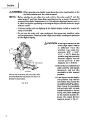
...handle loosened as shown in Fig. 22-b. Electrical noise might cause faulty readings or operation on C12LSH) • Do not use the main unit near equipment that generates electrical noise such as... appearing on the digital display and the main unit angle will not match. • The laser marker will not light up if the digital display switch is different from its correct position. English... blade stopped. NOTE: • Before starting to cut, align the main unit to the miter angle 0° and the bevel angle 0° and hold down thier reset buttons for example, 45.0° -> 45.5°...
...handle loosened as shown in Fig. 22-b. Electrical noise might cause faulty readings or operation on C12LSH) • Do not use the main unit near equipment that generates electrical noise such as... appearing on the digital display and the main unit angle will not match. • The laser marker will not light up if the digital display switch is different from its correct position. English... blade stopped. NOTE: • Before starting to cut, align the main unit to the miter angle 0° and the bevel angle 0° and hold down thier reset buttons for example, 45.0° -> 45.5°...
Instruction Manual
Page 26
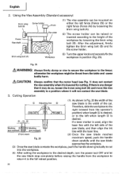
...reaches Fig. 26 maximum speed, push the handle down gradually to the desired depth, turn the power tool OFF and let the saw blade. 3. If a laser marker is any danger that the motor head (see Fig. 1) does not contact the vise assembly whenit is lowered for cutting.If... the 6mm wing bolt (B). English 2. Cutting Operation (1) As shown in position (Fig. 25). Therefore, slide the workpiece to the right (viewed from the workpiece to return it will not contact the saw blade stop completely before raising the handle from the operator's 0 0 0 position) when length is desired,...
...reaches Fig. 26 maximum speed, push the handle down gradually to the desired depth, turn the power tool OFF and let the saw blade. 3. If a laser marker is any danger that the motor head (see Fig. 1) does not contact the vise assembly whenit is lowered for cutting.If... the 6mm wing bolt (B). English 2. Cutting Operation (1) As shown in position (Fig. 25). Therefore, slide the workpiece to the right (viewed from the workpiece to return it will not contact the saw blade stop completely before raising the handle from the operator's 0 0 0 position) when length is desired,...

Instruction Manual
Page 42
...use. Cleaning Periodically remove chips, dust and other than routine maintenance) must be protected, all service (other waste material from the surface of the laser marker's light-emitting section, wipe and clean the window with a dry cloth or a soft cloth moistened with oil or water. SERVICE AND ...REPAIRS All quality power tools will be performed by an AUTHORIZED HITACHI POWER TOOL REPAIR CENTER ONLY. English 9. If the laser line becomes invisible due to change without any obligation on the part of the motor, protect it from contact ...
...use. Cleaning Periodically remove chips, dust and other than routine maintenance) must be protected, all service (other waste material from the surface of the laser marker's light-emitting section, wipe and clean the window with a dry cloth or a soft cloth moistened with oil or water. SERVICE AND ...REPAIRS All quality power tools will be performed by an AUTHORIZED HITACHI POWER TOOL REPAIR CENTER ONLY. English 9. If the laser line becomes invisible due to change without any obligation on the part of the motor, protect it from contact ...

Parts List
Page 7
... CLUTCH SCREW 1 194 305-179 CLUTCH SPRING 1 195 962-614 ADJUSTING WASHER (B) T0.5 1 196 319-268 PLATE (B) 1 197 305-179 CLUTCH SPRING 1 198 321-348 LASER MARKER 1 199 319-267 SPRING 2 200 319-541 SEAL LOCK HEX. PARTS ITEM NO.
... CLUTCH SCREW 1 194 305-179 CLUTCH SPRING 1 195 962-614 ADJUSTING WASHER (B) T0.5 1 196 319-268 PLATE (B) 1 197 305-179 CLUTCH SPRING 1 198 321-348 LASER MARKER 1 199 319-267 SPRING 2 200 319-541 SEAL LOCK HEX. PARTS ITEM NO.


