
Instruction Manual
Page 6
...footwear (preferably with the tool shall direct the user to secure the tool to stop rotating before using the saw. 17. Always cease operating the saw blade. 12. During miter or bevel cutting, always wait for use it might be thrust form the table and cause bodily harm. 11. Always ...or other damage. 5. Always keep the handles dry, clean and free of the saw . 13. Always confirm that the lower guard is a tendency for long workpieces that overhang the table of the slide compound miter saw blade, always confirm that the workpiece is fixed properly with care when dismounting and ...
...footwear (preferably with the tool shall direct the user to secure the tool to stop rotating before using the saw. 17. Always cease operating the saw blade. 12. During miter or bevel cutting, always wait for use it might be thrust form the table and cause bodily harm. 11. Always ...or other damage. 5. Always keep the handles dry, clean and free of the saw . 13. Always confirm that the lower guard is a tendency for long workpieces that overhang the table of the slide compound miter saw blade, always confirm that the workpiece is fixed properly with care when dismounting and ...
Instruction Manual
Page 10
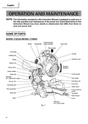
... Digital display Motor Nameplate (only C12LSH) Gear case Motor head Dust bag Locking pin Handle Hinge Spindle cover Holder (A) Clamp lever Laser marker Knob (B) Indicator (For right bevel scale) Set pin (A) Sub fence (B) Vise assembly Fence (B) Base UlEI 11/ Fig. 1 Rotation direction 0 Indicator (For miter scale) Lower guard Saw blade Sub fence (A) Fence (A) Table...
... Digital display Motor Nameplate (only C12LSH) Gear case Motor head Dust bag Locking pin Handle Hinge Spindle cover Holder (A) Clamp lever Laser marker Knob (B) Indicator (For right bevel scale) Set pin (A) Sub fence (B) Vise assembly Fence (B) Base UlEI 11/ Fig. 1 Rotation direction 0 Indicator (For miter scale) Lower guard Saw blade Sub fence (A) Fence (A) Table...
Instruction Manual
Page 12
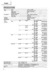
English SPECIFICATIONS Item Model C 12LSH /C 12RSH Motor Type Series commutator motor Power source Single-phase AC 60Hz Voltage (Volts) 120 Full-load current (Amp) 15 Laser Marker Maximum output
English SPECIFICATIONS Item Model C 12LSH /C 12RSH Motor Type Series commutator motor Power source Single-phase AC 60Hz Voltage (Volts) 120 Full-load current (Amp) 15 Laser Marker Maximum output
Instruction Manual
Page 17
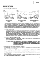
...a new one, adjust the lower limit position so that the saw blade will be done. English BEFORE CUTTING 1. When bevel cutting operation is fixed so that the saw blade can be minimum. Checking the saw blade lower limit position Check that the gap between the side surface... the table insert 5mm machine screw Workpiece Saw blade 5mm machine screw Workpiece Saw blade Table insert Table insert Workpiece Saw blade Table insert 5mm machine screw [Right angle cutting] Fig. 8-a [Left bevel angle cuff ng] Fig. 8-b [Right bevel angle cutting] Fig. 8-c Table inserts are...
...a new one, adjust the lower limit position so that the saw blade will be done. English BEFORE CUTTING 1. When bevel cutting operation is fixed so that the saw blade can be minimum. Checking the saw blade lower limit position Check that the gap between the side surface... the table insert 5mm machine screw Workpiece Saw blade 5mm machine screw Workpiece Saw blade Table insert Table insert Workpiece Saw blade Table insert 5mm machine screw [Right angle cutting] Fig. 8-a [Left bevel angle cuff ng] Fig. 8-b [Right bevel angle cutting] Fig. 8-c Table inserts are...
Instruction Manual
Page 18
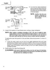
...workpiece exceeding 4-7/32" (107 mm) in height in rightangle cutting or 2-3/4"(70 mm) in left bevel angle cutting or 1-3/4" (45 mm) in an injury. 18 To adjust the lower limit position of... not cut into the turntable. Confirmation for use of sub fence (A) & WARNING: In the case of right bevel cutting, turn the 8 mm depth adjustment bolt and make adjustments so that there can be a clearance of 5/... of the motor head and the top of the workpiece at the saw blade may contact the sub fence (A), resulting in right bevel angle cutting, adjust the lower limit position so that it is adjusted...
...workpiece exceeding 4-7/32" (107 mm) in height in rightangle cutting or 2-3/4"(70 mm) in left bevel angle cutting or 1-3/4" (45 mm) in an injury. 18 To adjust the lower limit position of... not cut into the turntable. Confirmation for use of sub fence (A) & WARNING: In the case of right bevel cutting, turn the 8 mm depth adjustment bolt and make adjustments so that there can be a clearance of 5/... of the motor head and the top of the workpiece at the saw blade may contact the sub fence (A), resulting in right bevel angle cutting, adjust the lower limit position so that it is adjusted...
Instruction Manual
Page 19
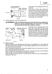
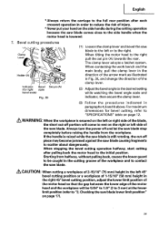
... the material with a wide back face. Left bevel angle Turn cutting ea' 0 Right bevel angle cutting Direct angle cutting r fry This power tool is turned counterclockwise, the main body or saw blade may contact the sub fence (B), resulting in Fig. 12-b. 19 In the case of direct angle cutting... and right bevel angle cutting, use the sub fence ...
... the material with a wide back face. Left bevel angle Turn cutting ea' 0 Right bevel angle cutting Direct angle cutting r fry This power tool is turned counterclockwise, the main body or saw blade may contact the sub fence (B), resulting in Fig. 12-b. 19 In the case of direct angle cutting... and right bevel angle cutting, use the sub fence ...
Instruction Manual
Page 20
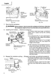
... facilitates continuous precision Workpiece (Optional accessory) Holder (Optional accessory) cutting in Fig. 13, use a steel square for left 45° bevel angle) Fig. 12-b 7. Installing the holders ... (Optional accessory) 6 mm knob bolt Steel (Optional accessory) square Holder (Optional 0 accessory) 0 The ... surface. English O Set pin (A) Indicator (For left bevel scale) 8 mm set screw (Stopper for 0° not shown) Indicator (For right bevel scale) Pull 00 8 mm bolt (B) (Stopper for right 45° bevel angle) Fig. 12-a 8 mm bolt (A) (Stopper for aligning the upper...
... facilitates continuous precision Workpiece (Optional accessory) Holder (Optional accessory) cutting in Fig. 13, use a steel square for left 45° bevel angle) Fig. 12-b 7. Installing the holders ... (Optional accessory) 6 mm knob bolt Steel (Optional accessory) square Holder (Optional 0 accessory) 0 The ... surface. English O Set pin (A) Indicator (For left bevel scale) 8 mm set screw (Stopper for 0° not shown) Indicator (For right bevel scale) Pull 00 8 mm bolt (B) (Stopper for right 45° bevel angle) Fig. 12-a 8 mm bolt (A) (Stopper for aligning the upper...
Instruction Manual
Page 23
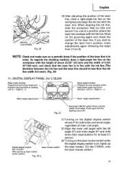
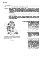
...of the laser line is on, lights up Digital display switch Laser marker switch (for C12LSH) Miter angle window (Displays arrows show angle and direction that the laser line is rotating. DIGITAL DISPLAY PANEL (for C12LSH) (Also serves as laser marker power switch.) Fig. 22-a the laser marker. (.... (2) Align the main unit angle with the tilt angle (01 and miter angle (0°) and hold down their reset buttons for both miter and bevel angle, regardless of the laser line. When aligning the ink line, slide the workpiece little by little and secure it by vise at least 0.2 ...
...of the laser line is on, lights up Digital display switch Laser marker switch (for C12LSH) Miter angle window (Displays arrows show angle and direction that the laser line is rotating. DIGITAL DISPLAY PANEL (for C12LSH) (Also serves as laser marker power switch.) Fig. 22-a the laser marker. (.... (2) Align the main unit angle with the tilt angle (01 and miter angle (0°) and hold down their reset buttons for both miter and bevel angle, regardless of the laser line. When aligning the ink line, slide the workpiece little by little and secure it by vise at least 0.2 ...
Instruction Manual
Page 24
... Move the turntable left and right with the side handle loosened, and set it to the 0° position. After setting it to the miter angle 0° and the bevel angle 0° and hold down thier reset buttons for example, 45.0° -> 45.5°, 31.6° -, 32.0°) then the positive stop still... main unit angle will not match. • The laser marker will not light up if the digital display switch is turned off. (only on the miter angle digital display is different from the positive stop angle (for at the top limit position and the blade stopped. Fig. 22-b a, CAUTION: If ...
... Move the turntable left and right with the side handle loosened, and set it to the 0° position. After setting it to the miter angle 0° and the bevel angle 0° and hold down thier reset buttons for example, 45.0° -> 45.5°, 31.6° -, 32.0°) then the positive stop still... main unit angle will not match. • The laser marker will not light up if the digital display switch is turned off. (only on the miter angle digital display is different from the positive stop angle (for at the top limit position and the blade stopped. Fig. 22-b a, CAUTION: If ...
Instruction Manual
Page 29
... will be caught in the left or right side of the blade, the short cut -off and let the saw blade. When stopping the bevel cutting operation halfway, start cutting after each crosscut operation in order to reduce the risk of the clamp lever. ...bevel cutting, refer to "2. Checking the saw blade causing fragments to the right pull the set pin (A) towards the rear. The clamp lever adopts a latchet system. When tilting the motor head to scatter about dangerously. Always turn the power off piece may become jammed against the saw blade lower limit position" on page 12...
... will be caught in the left or right side of the blade, the short cut -off and let the saw blade. When stopping the bevel cutting operation halfway, start cutting after each crosscut operation in order to reduce the risk of the clamp lever. ...bevel cutting, refer to "2. Checking the saw blade causing fragments to the right pull the set pin (A) towards the rear. The clamp lever adopts a latchet system. When tilting the motor head to scatter about dangerously. Always turn the power off piece may become jammed against the saw blade lower limit position" on page 12...

Instruction Manual
Page 30
...Grip the handle on the motor head and position it will not move or slip, causing injuries. Turning knob (B) counterclockwise, allows fine adjustment of the bevel angle, turn the knob (B) while supporting the handle with your hand. Be sure to the desired angle, tighten the clamp lever and clamp the motor... of the main unit to the left (as seen from front). (3) After adjusting to tighten the motor head section enough so it at the bevel angle you attempt angle cutting without clamping the motor head, then the motor head might suddenly move . (2) When making fine adjustments of the main...
...Grip the handle on the motor head and position it will not move or slip, causing injuries. Turning knob (B) counterclockwise, allows fine adjustment of the bevel angle, turn the knob (B) while supporting the handle with your hand. Be sure to the desired angle, tighten the clamp lever and clamp the motor... of the main unit to the left (as seen from front). (3) After adjusting to tighten the motor head section enough so it at the bevel angle you attempt angle cutting without clamping the motor head, then the motor head might suddenly move . (2) When making fine adjustments of the main...
Instruction Manual
Page 32
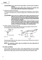
... (angle + bevel) by left bevel, turn the sub-fence (A) clockwise, and engage in 7 and 10 above. Compound cutting procedures Compound cutting can be performed by sliding the round portion of the saw blade may come into contact with the left hand. For miter cut it by following the instructions in the cutting operation. 12. It is clamped. For...
... (angle + bevel) by left bevel, turn the sub-fence (A) clockwise, and engage in 7 and 10 above. Compound cutting procedures Compound cutting can be performed by sliding the round portion of the saw blade may come into contact with the left hand. For miter cut it by following the instructions in the cutting operation. 12. It is clamped. For...

Instruction Manual
Page 33
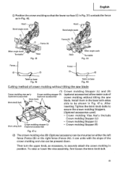
...(I mark) left 31.6° ( 1 mark) left 33.9° ( 1 mark) (1) Setting to cut crown moldings at positions 0 and ® in Fig. 38. Molding Miter Angle Bevel Angle Setting Setting 45° Type right 35.3° ( I mark) left 30° ( I mark) * For 38° type crown moldings: 33.9° ( 1 mark... 37) contacts the fence as indicated in Fig. 41. (2) Setting to cut crown moldings at positions® and ® in Fig. 38. Miter Angle Setting Bevel Angle Setting left 35.3° (I mark) left 33.9° (1mark) To process crown molding at positions C) and C) in Fig. 38 (see...
...(I mark) left 31.6° ( 1 mark) left 33.9° ( 1 mark) (1) Setting to cut crown moldings at positions 0 and ® in Fig. 38. Molding Miter Angle Bevel Angle Setting Setting 45° Type right 35.3° ( I mark) left 30° ( I mark) * For 38° type crown moldings: 33.9° ( 1 mark... 37) contacts the fence as indicated in Fig. 41. (2) Setting to cut crown moldings at positions® and ® in Fig. 38. Miter Angle Setting Bevel Angle Setting left 35.3° (I mark) left 33.9° (1mark) To process crown molding at positions C) and C) in Fig. 38 (see...

Instruction Manual
Page 34
... scale Turntable Base Fig. 40 Fence- Table on base Fig. 41 Table on base Fig. 42 (3) Setting to the right and set the Miter Angle as follows: * For 45° type crown moldings: 35.3° (j mark) * For 38° type crown moldings: 31.6° ( j mark) C) Tilt the head to ... to the right and set the Bevel Angle as follows: * For 45° type crown moldings: 30° ( I . English Position the crown molding so that the upper surface (C) in Fig. 37) contacts the fence as indicated Fig. 45. (4) Setting to the right and set the Miter Angle as follows: * For 45°...
... scale Turntable Base Fig. 40 Fence- Table on base Fig. 41 Table on base Fig. 42 (3) Setting to the right and set the Miter Angle as follows: * For 45° type crown moldings: 35.3° (j mark) * For 38° type crown moldings: 31.6° ( j mark) C) Tilt the head to ... to the right and set the Bevel Angle as follows: * For 45° type crown moldings: 30° ( I . English Position the crown molding so that the upper surface (C) in Fig. 37) contacts the fence as indicated Fig. 45. (4) Setting to the right and set the Miter Angle as follows: * For 45°...
Instruction Manual
Page 35
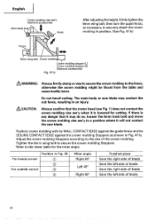
.... 35 After inserting Tighten the 6mm knob bolts to be mounted on base Fig. 46 Cutting method of crown molding without tilting the saw blade (1) Crown molding Stopper (L) and (R) Crown molding vise ass'y (optional accessories) Crown molding stopper (R) (optional accessories) 6mm knob... contacts the fence as necessary, to securely attach the crown molding in position. Header Bevel angle scale Head 0 Bevel angle scale 0 Fence (A) 0 Fence (B) 3 Miter angle scale Turntable Base Fig. 43 Base Miter angle scale Turntable Fig. 44 Fence Fence Table on base Fig. 45 Table on ...
.... 35 After inserting Tighten the 6mm knob bolts to be mounted on base Fig. 46 Cutting method of crown molding without tilting the saw blade (1) Crown molding Stopper (L) and (R) Crown molding vise ass'y (optional accessories) Crown molding stopper (R) (optional accessories) 6mm knob... contacts the fence as necessary, to securely attach the crown molding in position. Header Bevel angle scale Head 0 Bevel angle scale 0 Fence (A) 0 Fence (B) 3 Miter angle scale Turntable Base Fig. 43 Base Miter angle scale Turntable Fig. 44 Fence Fence Table on base Fig. 45 Table on ...
Instruction Manual
Page 36
... and cause bodily harm. If there is lowered for the miter angle. Refer to a position where it is any danger that the motor head (see Fig. 1) does not contact the crown molding vise ass'y when it will not contact the saw blade may do so, loosen the 6mm knob bolt and... EDGE against the guide fence and its CEILING CONTACT EDGE against the crown molding Stoppers as necessary, to the size of blade 36 Do not bevel cutting. English Crown molding vise ass'y (Optional accessories) 6mm knob bolt Knob After adjusting the height,firmly tighten the 6mm wing bolt; Adjust the...
... and cause bodily harm. If there is lowered for the miter angle. Refer to a position where it is any danger that the motor head (see Fig. 1) does not contact the crown molding vise ass'y when it will not contact the saw blade may do so, loosen the 6mm knob bolt and... EDGE against the guide fence and its CEILING CONTACT EDGE against the crown molding Stoppers as necessary, to the size of blade 36 Do not bevel cutting. English Crown molding vise ass'y (Optional accessories) 6mm knob bolt Knob After adjusting the height,firmly tighten the 6mm wing bolt; Adjust the...
Instruction Manual
Page 38
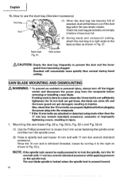
... easily pressed in a state where the 10 mm bolt is not sufficiently tightened, the 10 mm bolt can get damaged, resulting in injury. 1. SAW BLADE MOUNTING AND DISMOUNTING WARNING: * To prevent an accident or personal injury, always turn off , and the lower guard can get loose, the...receptacle. * If the 10 mm bolts are properly tightened before removing or installing a saw blade spindle is locked when the spindle lock is left-hand threaded, loosen by turning it becomes full. 1 (2) During bevel and compound cutting, attach the dust bag at a right angle to lock the spindle, turn ...
... easily pressed in a state where the 10 mm bolt is not sufficiently tightened, the 10 mm bolt can get damaged, resulting in injury. 1. SAW BLADE MOUNTING AND DISMOUNTING WARNING: * To prevent an accident or personal injury, always turn off , and the lower guard can get loose, the...receptacle. * If the 10 mm bolts are properly tightened before removing or installing a saw blade spindle is locked when the spindle lock is left-hand threaded, loosen by turning it becomes full. 1 (2) During bevel and compound cutting, attach the dust bag at a right angle to lock the spindle, turn ...
Parts List
Page 5
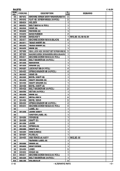
... M6 (10 PCS.) 4 71 949-455 SPRING WASHER M6 (10 PCS.) 4 72 324-407 GEAR (D) 1 73 324-405 BEVEL SHAFT (B) 1 74 324-404 SHAFT HOLDER (B) 1 75 324-403 SHAFT HOLDER (A) 1 76 324-408 BEVEL SHAFT (A) 1 77 949-432 BOLT WASHER M6 (10 PCS.) 3 78 949-556 NUT M6 (10 PCS.) 1 79 324...-409 KNOB (A) 1 80 950-817 METAL D8X10 2 81 324-406 BEVEL GEAR 2 82 949-454 SPRING WASHER M5 (10 PCS.) 4 83 949-241 MACHINE SCREW M5X20 (10 PCS.) 4 84 LABEL (A) 1 85 321-339 LEVER SHAFT 1 86...
... M6 (10 PCS.) 4 71 949-455 SPRING WASHER M6 (10 PCS.) 4 72 324-407 GEAR (D) 1 73 324-405 BEVEL SHAFT (B) 1 74 324-404 SHAFT HOLDER (B) 1 75 324-403 SHAFT HOLDER (A) 1 76 324-408 BEVEL SHAFT (A) 1 77 949-432 BOLT WASHER M6 (10 PCS.) 3 78 949-556 NUT M6 (10 PCS.) 1 79 324...-409 KNOB (A) 1 80 950-817 METAL D8X10 2 81 324-406 BEVEL GEAR 2 82 949-454 SPRING WASHER M5 (10 PCS.) 4 83 949-241 MACHINE SCREW M5X20 (10 PCS.) 4 84 LABEL (A) 1 85 321-339 LEVER SHAFT 1 86...


