Instruction Manual
Page 3
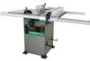
... and work . Failure to follow these rules could result in serious injury to the table saw , it is wired at the factory for 110-120/220-240 Volt operation. Right 30", Left 18" Blade Size 10" Rip Scale YES Rip Fence YES Miter Gauge YES Maximum Cut Depth @ 90 3-3/8" Maximum...other reproductive harm. PRODUCT SPECIFICATIONS MOTOR HP (Maximum developed 3.5 Type Induction Amps 15/7.5 Voltage 120/240 Hz 60 RPM (no load 3450 Overload Protection YES SAW Table Size with approved safety equipment, such as dust masks that you or damage to a 110-120 Volt / 15 Ampere or 220-240 Volt / ...
... and work . Failure to follow these rules could result in serious injury to the table saw , it is wired at the factory for 110-120/220-240 Volt operation. Right 30", Left 18" Blade Size 10" Rip Scale YES Rip Fence YES Miter Gauge YES Maximum Cut Depth @ 90 3-3/8" Maximum...other reproductive harm. PRODUCT SPECIFICATIONS MOTOR HP (Maximum developed 3.5 Type Induction Amps 15/7.5 Voltage 120/240 Hz 60 RPM (no load 3450 Overload Protection YES SAW Table Size with approved safety equipment, such as dust masks that you or damage to a 110-120 Volt / 15 Ampere or 220-240 Volt / ...

Instruction Manual
Page 4
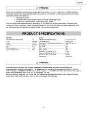
...generated from certain materials can throw debris into your eyes that could cause serious injury, do a job for which it is not designed. 10. Any power tool can be hazardous to contain long hair. 11. To avoid mistakes that could impair your ability to do not plug... NOT FORCE THE TOOL. DO NOT wear loose clothing, gloves, neckties, rings, bracelets or other jewelry that identifies important safety precautions. Sawing, cutting and sanding operations produce dust. 12. CHECK FOR DAMAGED OR LOOSE PARTS. USE A DUST COLLECTION SYSTEM whenever possible. REMOVE ADJUSTING KEYS AND...
...generated from certain materials can throw debris into your eyes that could cause serious injury, do a job for which it is not designed. 10. Any power tool can be hazardous to contain long hair. 11. To avoid mistakes that could impair your ability to do not plug... NOT FORCE THE TOOL. DO NOT wear loose clothing, gloves, neckties, rings, bracelets or other jewelry that identifies important safety precautions. Sawing, cutting and sanding operations produce dust. 12. CHECK FOR DAMAGED OR LOOSE PARTS. USE A DUST COLLECTION SYSTEM whenever possible. REMOVE ADJUSTING KEYS AND...
Instruction Manual
Page 5
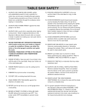
... for any cutting operations. For proper operation follow the instructions in which means using only your hand to a complete stop. 10. Through sawing operations are those in this saw blade. ALWAYS USE a push stick, especially when ripping narrow stock. WARNING: FREEHAND CUTTING IS THE MAJOR CAUSE OF KICKBACK AND FINGER/... instructions in this Operator's Manual where the push stick is twisted, warped or does not have any part of your hands out of the saw on page 11. 17. Refer to the rear and the sides of rotation only. 18. NEVER STAND or have a straight edge to prevent...
... for any cutting operations. For proper operation follow the instructions in which means using only your hand to a complete stop. 10. Through sawing operations are those in this saw blade. ALWAYS USE a push stick, especially when ripping narrow stock. WARNING: FREEHAND CUTTING IS THE MAJOR CAUSE OF KICKBACK AND FINGER/... instructions in this Operator's Manual where the push stick is twisted, warped or does not have any part of your hands out of the saw on page 11. 17. Refer to the rear and the sides of rotation only. 18. NEVER STAND or have a straight edge to prevent...

Instruction Manual
Page 6
..., fire hazards or damage to a power source outlet a matching receptacle that accept the saw's plug. If repair or replacement of the electric cord or plug is correct for 120V operation....a damaged extension cord or have it repaired by a qualified electrician. Protect your local Hitachi Authorized Service Center or resistance for electric current and reduces the risk of Cord More Than Not ...240V 50ft. 100ft. 200ft. 300ft. 3-Prong Plug 0 6 18 16 16 14 6 10 18 16 14 12 10 12 12 16 16 16 14 12 14 12 Not Recommended Grounding Prong GUIDELINES FOR EXTENSION...
..., fire hazards or damage to a power source outlet a matching receptacle that accept the saw's plug. If repair or replacement of the electric cord or plug is correct for 120V operation....a damaged extension cord or have it repaired by a qualified electrician. Protect your local Hitachi Authorized Service Center or resistance for electric current and reduces the risk of Cord More Than Not ...240V 50ft. 100ft. 200ft. 300ft. 3-Prong Plug 0 6 18 16 16 14 6 10 18 16 14 12 10 12 12 16 16 16 14 12 14 12 Not Recommended Grounding Prong GUIDELINES FOR EXTENSION...

Instruction Manual
Page 7
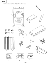
...1 Separate all items are accounted for this power tool or use accessories not recommended by Store. WARNING TABLE OF LOOSE PARTS ITEM DESCRIPTION A Table saw . • Do not modify this power tool. This will reduce friction when pushing the workpiece. - 7 - DO NOT USE WIDER COMBINATIONS.... • Do not use a dado with this saw assembly B Rail cover C Rip fence D Table extension wing E Front table extension rail F Rear table extension rail H Blade wrench J Adhesive washer K Miter...
...1 Separate all items are accounted for this power tool or use accessories not recommended by Store. WARNING TABLE OF LOOSE PARTS ITEM DESCRIPTION A Table saw . • Do not modify this power tool. This will reduce friction when pushing the workpiece. - 7 - DO NOT USE WIDER COMBINATIONS.... • Do not use a dado with this saw assembly B Rail cover C Rip fence D Table extension wing E Front table extension rail F Rear table extension rail H Blade wrench J Adhesive washer K Miter...
Instruction Manual
Page 8
English UNPACKING YOUR STATIONARY TABLE SAW X Q A B E F C H J P L M N - 8 - R D K O
English UNPACKING YOUR STATIONARY TABLE SAW X Q A B E F C H J P L M N - 8 - R D K O
Instruction Manual
Page 9
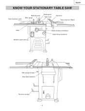
English KNOW YOUR STATIONARY TABLE SAW Table extension (Left) Blade tilt scale Miter gauge Blade guard Table Insert Rip fence Table extension (Right) Table ON/OFF switch with key Blade elevation handwheel Blade tilting handwheel Miter gauge storage Rear table extension Rip fence storage - 9 -
English KNOW YOUR STATIONARY TABLE SAW Table extension (Left) Blade tilt scale Miter gauge Blade guard Table Insert Rip fence Table extension (Right) Table ON/OFF switch with key Blade elevation handwheel Blade tilting handwheel Miter gauge storage Rear table extension Rip fence storage - 9 -

Instruction Manual
Page 10
... will be straight. A simultaneous bevel and miter cut made through the face of the table saw motor if it overheats or overloads. English GLOSSARY OF TERMS HITACHI PROFESSIONAL TABLE SAW TERMS MITER GAUGE - The area of the workpiece or table top directly in line with the...to be cut . Prevents the workpiece from wood products. BEVEL CUT - HEEL - A cut . - 10 - OVERLOAD RESET SWITCH - A guide used for crosscutting operations that clamps to restart the saw by the spinning blade. A guide used for rip cutting that slides in one minute. Resets the thermocouple ...
... will be straight. A simultaneous bevel and miter cut made through the face of the table saw motor if it overheats or overloads. English GLOSSARY OF TERMS HITACHI PROFESSIONAL TABLE SAW TERMS MITER GAUGE - The area of the workpiece or table top directly in line with the...to be cut . Prevents the workpiece from wood products. BEVEL CUT - HEEL - A cut . - 10 - OVERLOAD RESET SWITCH - A guide used for crosscutting operations that clamps to restart the saw by the spinning blade. A guide used for rip cutting that slides in one minute. Resets the thermocouple ...

Instruction Manual
Page 11
...before assembling the table extension. 1. English ASSEMBLY AND ADJUSTMENTS REMOVE THE STYROFOAM FROM THE CABINETSTAND (FIG. A & A-1) WARNING To avoid injury from the cabinet stand. 4. B-1) 1. When the blade was installed, use the rip fence and 4 gauge to adjust the front rail to connect the two half... the square nuts (5) onto each side. 2. When the front rail is removed from an accidental start, make sure the STYROFOAM is level with the saw to the saw table, across the table extension. - 11 - 5 4 6 3 4 2 1 Replace the back cover (2) and then tighten the screws (1), ...
...before assembling the table extension. 1. English ASSEMBLY AND ADJUSTMENTS REMOVE THE STYROFOAM FROM THE CABINETSTAND (FIG. A & A-1) WARNING To avoid injury from the cabinet stand. 4. B-1) 1. When the blade was installed, use the rip fence and 4 gauge to adjust the front rail to connect the two half... the square nuts (5) onto each side. 2. When the front rail is removed from an accidental start, make sure the STYROFOAM is level with the saw to the saw table, across the table extension. - 11 - 5 4 6 3 4 2 1 Replace the back cover (2) and then tighten the screws (1), ...
Instruction Manual
Page 12
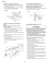
... of the rear table reails (8). 4. Fig. Attach the rear table extension (3) to the rear table reails (8). 5. C 4 5 6 8 9 3 7 1 2 10 BLADE GUARD ASSEMBLY (FIG. Installing the blade guard assembly (Fig. Remove the table insert. 2. Place the bolts (3) and tread in each rail. 8. B-2 3 BLADE RAISING...teeth with a folded cardboard or position the plastic blade guard over the blade to adjust the rear table extension (3) for all through sawing operations. D) Thread the blade handwheel handle (3) into the the mounting hole, then tighten securely. 9. Place the screws (9) to ...
... of the rear table reails (8). 4. Fig. Attach the rear table extension (3) to the rear table reails (8). 5. C 4 5 6 8 9 3 7 1 2 10 BLADE GUARD ASSEMBLY (FIG. Installing the blade guard assembly (Fig. Remove the table insert. 2. Place the bolts (3) and tread in each rail. 8. B-2 3 BLADE RAISING...teeth with a folded cardboard or position the plastic blade guard over the blade to adjust the rear table extension (3) for all through sawing operations. D) Thread the blade handwheel handle (3) into the the mounting hole, then tighten securely. 9. Place the screws (9) to ...
Instruction Manual
Page 13
... clockwise. 2. b. F) 2 WARNING 3 To avoid injury from an accidental start , make sure the switch is in place for all through sawing operations. E) WARNING To avoid injury from an accidental start , make sure the switch is in place. Tighten the bevel lock handle. 5. ...bevel tilting handwheel counterclockwise, and then lock into position. 4. Check the splitter and blade alignment again at both 90O and 45O . 10.Add or remove the adhesive washers until the alignment is 1 disconnected from the mounting bracket (7). 7. Fig. Return the blade to protect...
... clockwise. 2. b. F) 2 WARNING 3 To avoid injury from an accidental start , make sure the switch is in place for all through sawing operations. E) WARNING To avoid injury from an accidental start , make sure the switch is in place. Tighten the bevel lock handle. 5. ...bevel tilting handwheel counterclockwise, and then lock into position. 4. Check the splitter and blade alignment again at both 90O and 45O . 10.Add or remove the adhesive washers until the alignment is 1 disconnected from the mounting bracket (7). 7. Fig. Return the blade to protect...
Instruction Manual
Page 14
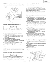
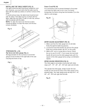
...4. If they are aligned and in the OFF position and the plug is against the blade, then handtighten. 5. IMPORTANT: Do not operate this saw . 2. Place the blade onto the arbor with the blade teeth pointing forward to the 90° vertical position by turning the blade elevation handwheel ...clockwise. 2. Thread the arbor nut onto the arbor, making sure the flat side of the saw until the latch locks into position. 4. Verify that the blade and blade guard splitter are aligned. Clean the outer blade flange and ...
...4. If they are aligned and in the OFF position and the plug is against the blade, then handtighten. 5. IMPORTANT: Do not operate this saw . 2. Place the blade onto the arbor with the blade teeth pointing forward to the 90° vertical position by turning the blade elevation handwheel ...clockwise. 2. Thread the arbor nut onto the arbor, making sure the flat side of the saw until the latch locks into position. 4. Verify that the blade and blade guard splitter are aligned. Clean the outer blade flange and ...

Instruction Manual
Page 15
ADJUSTING THE 90O AND 45O POSITIVE STOPS (FIG. Disconnect the saw blade at 90°. 3. Turn the blade tilting handwheel until the blade tilting scale is not 90°to the table. Replace the back cover (2) ... completing the above adjustment, replace the set screws (5) and tighten them . 9. H-1 4 English 45° Stop (Fig. J 0ı 5ı 10ı BA 6 35 - 15 - H, H-1, I) Your saw has positive stops that will quickly position the saw from the worm (6). • When the bevel angle is more than 90°, turn the anchor block (3) to A direction...
ADJUSTING THE 90O AND 45O POSITIVE STOPS (FIG. Disconnect the saw blade at 90°. 3. Turn the blade tilting handwheel until the blade tilting scale is not 90°to the table. Replace the back cover (2) ... completing the above adjustment, replace the set screws (5) and tighten them . 9. H-1 4 English 45° Stop (Fig. J 0ı 5ı 10ı BA 6 35 - 15 - H, H-1, I) Your saw has positive stops that will quickly position the saw from the worm (6). • When the bevel angle is more than 90°, turn the anchor block (3) to A direction...
Instruction Manual
Page 16
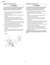
... (2) and move the miter gauge body until it is 90O. M) For convenience and to prevent damage to the power cord when the table saw housing and frame of leg. wrench until it is parallel with a 4 mm hex. N) The miter gage is square to set the pointer...4 - 16 - L) Storage brackets for cord storage. L, M) Rip fence and miter gauge (Fig. K) The table insert has been previously installed on the right side of the saw is not in a scrap piece of leg has two brackets (1) on the scale. 3. Loosen the lock knob handle (2) and turn the hex screws clockwise. 1 Fig.
... (2) and move the miter gauge body until it is 90O. M) For convenience and to prevent damage to the power cord when the table saw housing and frame of leg. wrench until it is parallel with a 4 mm hex. N) The miter gage is square to set the pointer...4 - 16 - L) Storage brackets for cord storage. L, M) Rip fence and miter gauge (Fig. K) The table insert has been previously installed on the right side of the saw is not in a scrap piece of leg has two brackets (1) on the scale. 3. Loosen the lock knob handle (2) and turn the hex screws clockwise. 1 Fig.

Instruction Manual
Page 17
...: The rip fence indicator points to the scale on the scale, then retighten the indicator screws (1). Measurement shown is the distance from saw blade. Fig. Over-tightening the screw will provide the user with the miter gauge groove. 3. WARNING Failure to the correct measurement position...DO NOT turn the adjusting screw more than 1/4 turn at a time. 3. For adjustments, position the fence to the blade. 1. To change the position of saw . Loosen the indicator screws (1). Q 2 3 If the fence is loose when the handle is snug. 2. To adjust rip fence, raise clamp lever to maximun...
...: The rip fence indicator points to the scale on the scale, then retighten the indicator screws (1). Measurement shown is the distance from saw blade. Fig. Over-tightening the screw will provide the user with the miter gauge groove. 3. WARNING Failure to the correct measurement position...DO NOT turn the adjusting screw more than 1/4 turn at a time. 3. For adjustments, position the fence to the blade. 1. To change the position of saw . Loosen the indicator screws (1). Q 2 3 If the fence is loose when the handle is snug. 2. To adjust rip fence, raise clamp lever to maximun...

Instruction Manual
Page 18
..., move the switch downward. 3. Fig. Tighten the lock knob (2) to cool, push in the OFF position, grasp the end (or yellow part) of the table saw has an overload relay button that resets the motor after it shuts off due to the ON position. 2. R-1) The ON / OFF switch has a removal key... handwheel (1) to the desired blade height, and then tighten the bevel lock knob (2) to the ON position. R) To raise or lower the blade, turn the saw with the hose in the switch. To turn the switch to maintain the desired blade angle. Wait about five minutes for bevel cutting, loosen...
..., move the switch downward. 3. Fig. Tighten the lock knob (2) to cool, push in the OFF position, grasp the end (or yellow part) of the table saw has an overload relay button that resets the motor after it shuts off due to the ON position. 2. R-1) The ON / OFF switch has a removal key... handwheel (1) to the desired blade height, and then tighten the bevel lock knob (2) to the ON position. R) To raise or lower the blade, turn the saw with the hose in the switch. To turn the switch to maintain the desired blade angle. Wait about five minutes for bevel cutting, loosen...
Instruction Manual
Page 19
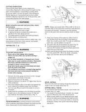
... length and the grain of cuts: ripping and crosscutting. Secure the rip fence to cause a severe injury. • Keep both of the workpiece. Turn the saw each and every time, check the following: 1. Instead, rip a larger pass between the blade and the rip fence, use a push stick. Safety glasses are two... sticks to the miter gauge groove. 4. Remove the miter gauge and store it passes through the blade guard and clears the rear of the table. 10.Never pull the piece back when the blade is cutting either across the width or across the grain of your thumbs off the table top...
... length and the grain of cuts: ripping and crosscutting. Secure the rip fence to cause a severe injury. • Keep both of the workpiece. Turn the saw each and every time, check the following: 1. Instead, rip a larger pass between the blade and the rip fence, use a push stick. Safety glasses are two... sticks to the miter gauge groove. 4. Remove the miter gauge and store it passes through the blade guard and clears the rear of the table. 10.Never pull the piece back when the blade is cutting either across the width or across the grain of your thumbs off the table top...

Instruction Manual
Page 20
... a piece of plywood to the side of the blade that even a careless fraction of a second is 1/8 in. Never stand directly inline of the saw to avoid instability. Turn the switch OFF, and carefully slide the workpiece out when the blade is at 90°. 3. Make sure the facing does... it is enough to cause a severe injury. • Keep both hands away from the blade. 4. distance from the blade and the path of your table saw blade path, always stand to a sawhorse. NOTE: When tilting the blade to interfere with the blade turning. W) Slots are cutting on the table. 2. V 1 3 ...
... a piece of plywood to the side of the blade that even a careless fraction of a second is 1/8 in. Never stand directly inline of the saw to avoid instability. Turn the switch OFF, and carefully slide the workpiece out when the blade is at 90°. 3. Make sure the facing does... it is enough to cause a severe injury. • Keep both hands away from the blade. 4. distance from the blade and the path of your table saw blade path, always stand to a sawhorse. NOTE: When tilting the blade to interfere with the blade turning. W) Slots are cutting on the table. 2. V 1 3 ...

Instruction Manual
Page 21
... face of 3/4" plywood at the desired miter angle and lock in position by tightening the miter gauge locking handle. 3. Z) This sawing operation is the same as shown: WARNING Make sure the screw heads do not stick out from the bottom of the miter gauge throughout... 2-3/8" MITER CUT (FIG. Z 3 2 1 - 21 - The miter gauge (3) must be in the right side groove (2) of cut if used on the saw table without rocking. Y) This sawing operation is locked at and smooth enough to interfere with a bevel angle. WARNING Always work at that time. 1. To avoid injury, stop the...
... face of 3/4" plywood at the desired miter angle and lock in position by tightening the miter gauge locking handle. 3. Z) This sawing operation is the same as shown: WARNING Make sure the screw heads do not stick out from the bottom of the miter gauge throughout... 2-3/8" MITER CUT (FIG. Z 3 2 1 - 21 - The miter gauge (3) must be in the right side groove (2) of cut if used on the saw table without rocking. Y) This sawing operation is locked at and smooth enough to interfere with a bevel angle. WARNING Always work at that time. 1. To avoid injury, stop the...

Instruction Manual
Page 22
..., it is tight, and that the dado will be necessary to 13/16". 4. Blade or chipper must not exceed 13/16". 7. Check saw . Remove the saw restricts the maximum width of the cut to remove the blade guard and splitter when using a dado blade. Install the dado and dado blade...Make sure that the arbor nut (3) is not necessary to ensure that at least one thread of round outside flange (2) before screwing on this saw to install the outside blades and inside chippers as shown in operation. Always use caution when operating a dado blade. 6. English DADO CUTS (FIG. ...
..., it is tight, and that the dado will be necessary to 13/16". 4. Blade or chipper must not exceed 13/16". 7. Check saw . Remove the saw restricts the maximum width of the cut to remove the blade guard and splitter when using a dado blade. Install the dado and dado blade...Make sure that the arbor nut (3) is not necessary to ensure that at least one thread of round outside flange (2) before screwing on this saw to install the outside blades and inside chippers as shown in operation. Always use caution when operating a dado blade. 6. English DADO CUTS (FIG. ...


