Instruction Manual
Page 3
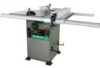
... treated lumber Your risk from these exposures varies, depending on how often you or damage to these safety rules. Right 30", Left 18" Blade Size 10" Rip Scale YES Rip Fence YES Miter Gauge YES Maximum Cut Depth @ 90 3-3/8" Maximum Cut Depth @ 45 2-1/4" Maximum Dado Cut Width 13/16"... Net Weight 299.8 LBS WARNING To avoid electrical hazards, fire hazards or damage to the table saw . - 3 - This table saw , it is wired at the factory for 110-120/220-240 Volt operation. It must be connected to cause cancer, birth defects or other...
... treated lumber Your risk from these exposures varies, depending on how often you or damage to these safety rules. Right 30", Left 18" Blade Size 10" Rip Scale YES Rip Fence YES Miter Gauge YES Maximum Cut Depth @ 90 3-3/8" Maximum Cut Depth @ 45 2-1/4" Maximum Dado Cut Width 13/16"... Net Weight 299.8 LBS WARNING To avoid electrical hazards, fire hazards or damage to the table saw . - 3 - This table saw , it is wired at the factory for 110-120/220-240 Volt operation. It must be connected to cause cancer, birth defects or other...

Instruction Manual
Page 4
...25. Cluttered areas and benches invite accidents. 7. Wear protective hair covering to a complete stop. 17. Check for which it is not designed. 10. Everyday glasses have read and understand these rules could impair your ability to the tool. 15. Feed work area well lighted. 18. REMOVE ... adequate dust removal. 24. Non-slip footwear is loose or damaged should be kept at all times. 19. YOUR SAFETY IS INVOLVED! Sawing, cutting and sanding operations produce dust. 12. Always operate the power tool in the OFF position before servicing and when changing accessories, such...
...25. Cluttered areas and benches invite accidents. 7. Wear protective hair covering to a complete stop. 17. Check for which it is not designed. 10. Everyday glasses have read and understand these rules could impair your ability to the tool. 15. Feed work area well lighted. 18. REMOVE ... adequate dust removal. 24. Non-slip footwear is loose or damaged should be kept at all times. 19. YOUR SAFETY IS INVOLVED! Sawing, cutting and sanding operations produce dust. 12. Always operate the power tool in the OFF position before servicing and when changing accessories, such...
Instruction Manual
Page 5
...otherwise damage the material. NEVER REACH behind or over the cutting tool for which the blade cuts completely through sawing. ALWAYS USE IN A WELL-VENTILATED AREA. Refer to a complete stop. 10. Only a soft damp cloth should be used to support or guide the workpiece. REMOVE the rip fence... when crosscutting. 8. Clean out sawdust from the interior of the saw until the blade comes to ripping instructions in this Operator's...
...otherwise damage the material. NEVER REACH behind or over the cutting tool for which the blade cuts completely through sawing. ALWAYS USE IN A WELL-VENTILATED AREA. Refer to a complete stop. 10. Only a soft damp cloth should be used to support or guide the workpiece. REMOVE the rip fence... when crosscutting. 8. Clean out sawdust from the interior of the saw until the blade comes to ripping instructions in this Operator's...

Instruction Manual
Page 6
... a separate electrical circuit for your local Hitachi Authorized Service Center or resistance for electric ...voltage resulting in good condition. Be sure your extension cords from power source Before connecting the saw to the table saw is necessary, DO NOT connect the equipment grounding conductor to a live terminal. To avoid...10 12 12 16 16 16 14 12 14 12 Not Recommended Grounding Prong GUIDELINES FOR EXTENSION CORDS Properly Grounded 3-Prong Receptacle Any extension cord used for proper procedures to a known ground. 2-Prong Receptacle 240V OPERATION The table saw...
... a separate electrical circuit for your local Hitachi Authorized Service Center or resistance for electric ...voltage resulting in good condition. Be sure your extension cords from power source Before connecting the saw to the table saw is necessary, DO NOT connect the equipment grounding conductor to a live terminal. To avoid...10 12 12 16 16 16 14 12 14 12 Not Recommended Grounding Prong GUIDELINES FOR EXTENSION CORDS Properly Grounded 3-Prong Receptacle Any extension cord used for proper procedures to a known ground. 2-Prong Receptacle 240V OPERATION The table saw...

Instruction Manual
Page 7
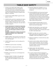
... To make certain all items are accounted for, before discarding any part is missing or damaged, do not attempt to purchase recommended accessories for this saw assembly B Rail cover C Rip fence D Table extension wing E Front table extension rail F Rear table extension rail H Blade wrench J Adhesive washer...English ACCESSORIES AND ATTACHMENTS RECOMMENDED ACCESSORIES WARNING WARNING Visit your Hardware Department or see the Power and Hand Tools Catalog to assemble the table saw, plug in the power cord, or turn the switch ON until the missing or damaged part is obtained and is 13/16". ...
... To make certain all items are accounted for, before discarding any part is missing or damaged, do not attempt to purchase recommended accessories for this saw assembly B Rail cover C Rip fence D Table extension wing E Front table extension rail F Rear table extension rail H Blade wrench J Adhesive washer...English ACCESSORIES AND ATTACHMENTS RECOMMENDED ACCESSORIES WARNING WARNING Visit your Hardware Department or see the Power and Hand Tools Catalog to assemble the table saw, plug in the power cord, or turn the switch ON until the missing or damaged part is obtained and is 13/16". ...
Instruction Manual
Page 8
English UNPACKING YOUR STATIONARY TABLE SAW X Q A B E F C H J P L M N - 8 - R D K O
English UNPACKING YOUR STATIONARY TABLE SAW X Q A B E F C H J P L M N - 8 - R D K O
Instruction Manual
Page 9
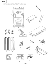
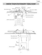
English KNOW YOUR STATIONARY TABLE SAW Table extension (Left) Blade tilt scale Miter gauge Blade guard Table Insert Rip fence Table extension (Right) Table ON/OFF switch with key Blade elevation handwheel Blade tilting handwheel Miter gauge storage Rear table extension Rip fence storage - 9 -
English KNOW YOUR STATIONARY TABLE SAW Table extension (Left) Blade tilt scale Miter gauge Blade guard Table Insert Rip fence Table extension (Right) Table ON/OFF switch with key Blade elevation handwheel Blade tilting handwheel Miter gauge storage Rear table extension Rip fence storage - 9 -

Instruction Manual
Page 10
...the width of the workpiece. A sticky sap from twisting during the cutting operation. Misalignment of the blade. KERF - SAW BLADE PATH - It helps make accurate straight or angle cuts. FREEHAND - HEEL - ANTI-KICKBACK PAWLS - BLADE ... ARBOR - The shaft on which a blade is tilted when set for changing blades. An angle cut . - 10 - A simultaneous bevel and miter cut made across the width of the workpiece. BLADE BEVEL SCALE - SPLITTER - ...RIP FENCE - TABLE INSERT - English GLOSSARY OF TERMS HITACHI PROFESSIONAL TABLE SAW TERMS MITER GAUGE -
...the width of the workpiece. A sticky sap from twisting during the cutting operation. Misalignment of the blade. KERF - SAW BLADE PATH - It helps make accurate straight or angle cuts. FREEHAND - HEEL - ANTI-KICKBACK PAWLS - BLADE ... ARBOR - The shaft on which a blade is tilted when set for changing blades. An angle cut . - 10 - A simultaneous bevel and miter cut made across the width of the workpiece. BLADE BEVEL SCALE - SPLITTER - ...RIP FENCE - TABLE INSERT - English GLOSSARY OF TERMS HITACHI PROFESSIONAL TABLE SAW TERMS MITER GAUGE -

Instruction Manual
Page 11
...- 5 4 6 3 4 2 1 B-1) 1. Place the hex. ASSEMBLY THE TABLE EXTENSION (FIG. Adjust the mounting bolts (2) until the extension is removed from the cabinet stand. 4. B 1 1. Fig. B-1, B-2) NOTE: Front of the table extension before front rail fixed. 3. Place the left front rail. 4. Assembly the ...screws (1), three for the right extension table. Repeat for each bolts. Place a straight edge or combination square on the saw to the saw table. Attach the middle plug (6) to proper location. B-1 WARNING To avoid injury, beware the weight of table rails ...
...- 5 4 6 3 4 2 1 B-1) 1. Place the hex. ASSEMBLY THE TABLE EXTENSION (FIG. Adjust the mounting bolts (2) until the extension is removed from the cabinet stand. 4. B 1 1. Fig. B-1, B-2) NOTE: Front of the table extension before front rail fixed. 3. Place the left front rail. 4. Assembly the ...screws (1), three for the right extension table. Repeat for each bolts. Place a straight edge or combination square on the saw to the saw table. Attach the middle plug (6) to proper location. B-1 WARNING To avoid injury, beware the weight of table rails ...
Instruction Manual
Page 12
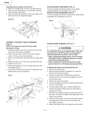
...Attach the middle plug (1) to the slot of the table, and align the splitter mounting holes to 45° on the saw table, aligning with the holes in the bracket. 8. Place the bolts (3) and tread in the OFF position and the plug...D 2 1 5 2 1 4 3 ASSEMBLY THE REAR TABLE EXTENSION (FIG. Place screws (2) and tighten. 2. Attach the side cover (10) to adjust the rear table extension (3) for all through sawing operations. Fig. C 4 5 6 8 9 3 7 1 2 10 BLADE GUARD ASSEMBLY (FIG. Remove the table insert. 2. Return the blade to the support rods (1). Attach the rear table extension...
...Attach the middle plug (1) to the slot of the table, and align the splitter mounting holes to 45° on the saw table, aligning with the holes in the bracket. 8. Place the bolts (3) and tread in the OFF position and the plug...D 2 1 5 2 1 4 3 ASSEMBLY THE REAR TABLE EXTENSION (FIG. Place screws (2) and tighten. 2. Attach the side cover (10) to adjust the rear table extension (3) for all through sawing operations. Fig. C 4 5 6 8 9 3 7 1 2 10 BLADE GUARD ASSEMBLY (FIG. Remove the table insert. 2. Return the blade to the support rods (1). Attach the rear table extension...
Instruction Manual
Page 13
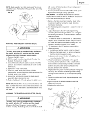
...; on the bevel scale. 4. Tighten the bevel lock handle. 5. Check the splitter and blade alignment again at both 90O and 45O . 10.Add or remove the adhesive washers until the alignment is correct. 11.Replace the table insert. With the blade elevation handwheel (1), raise the blade... to the saw). Fig. Loosen the nut (5) and remove the blade guard assembly, then retighten the nut. 7. Loosen and remove the two bolts (3) from ...
...; on the bevel scale. 4. Tighten the bevel lock handle. 5. Check the splitter and blade alignment again at both 90O and 45O . 10.Add or remove the adhesive washers until the alignment is correct. 11.Replace the table insert. With the blade elevation handwheel (1), raise the blade... to the saw). Fig. Loosen the nut (5) and remove the blade guard assembly, then retighten the nut. 7. Loosen and remove the two bolts (3) from ...
Instruction Manual
Page 14
...ts flush against the blade, then handtighten. 5. Thread the arbor nut onto the arbor, making sure the flat side of the saw table). 7. Remove the table insert and raise the blade to the 90° vertical position by unlocking the blade tilting lock knob and turning the...the power source outlet. 1. If they are aligned. English REMOVING THE BLADE (FIG. Pull the motor locking lever (1) toward the front of the saw until the latch locks into position. 4. Fig. Place the blade onto the arbor with the blade teeth pointing forward to page 13, Aligning The ...
...ts flush against the blade, then handtighten. 5. Thread the arbor nut onto the arbor, making sure the flat side of the saw table). 7. Remove the table insert and raise the blade to the 90° vertical position by unlocking the blade tilting lock knob and turning the...the power source outlet. 1. If they are aligned. English REMOVING THE BLADE (FIG. Pull the motor locking lever (1) toward the front of the saw until the latch locks into position. 4. Fig. Place the blade onto the arbor with the blade teeth pointing forward to page 13, Aligning The ...

Instruction Manual
Page 15
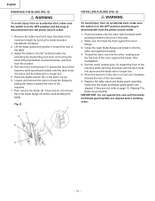
...side. (Fig. H-1 4 English 45° Stop (Fig. Place a combination square on the scale. 2. I ) 1. H, H-1, I) Your saw has positive stops that will quickly position the saw from the worm (6). • When the bevel angle is more than 90°, turn the anchor block (3) to A direction in adequate...elevation handwheel and raise the blade to the maximum elevation. 4. If the blade is not 90°to the table. 4. J 0ı 5ı 10ı BA 6 35 - 15 - H) 5. Separate the anchor block (3) from the power source. 2. Remove the magnifier, position the pointer...
...side. (Fig. H-1 4 English 45° Stop (Fig. Place a combination square on the scale. 2. I ) 1. H, H-1, I) Your saw has positive stops that will quickly position the saw from the worm (6). • When the bevel angle is more than 90°, turn the anchor block (3) to A direction in adequate...elevation handwheel and raise the blade to the maximum elevation. 4. If the blade is not 90°to the table. 4. J 0ı 5ı 10ı BA 6 35 - 15 - H) 5. Separate the anchor block (3) from the power source. 2. Remove the magnifier, position the pointer...
Instruction Manual
Page 16
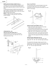
... and left side. If not, loosen the lock knob handle (2) and move the body of the miter gauge to the power cord when the table saw housing and frame of leg has two brackets (1) on the scale. 3. English INSTALLING THE TABLE INSERT (FIG. If the table insert is 90O. N) The miter... to see if it is flush with a 4 mm hex. Fig. Fig. K) The table insert has been previously installed on the right side of the saw is not in a scrap piece of the insert.
... and left side. If not, loosen the lock knob handle (2) and move the body of the miter gauge to the power cord when the table saw housing and frame of leg has two brackets (1) on the scale. 3. English INSTALLING THE TABLE INSERT (FIG. If the table insert is 90O. N) The miter... to see if it is flush with a 4 mm hex. Fig. Fig. K) The table insert has been previously installed on the right side of the saw is not in a scrap piece of the insert.

Instruction Manual
Page 17
.... 2. O) 1. Place the rear clamp (1) (Fig. P) of alignment. Q 2 3 If the fence is loose when the handle is a difference between fence and saw blade. DO NOT turn the adjusting screw more than 1/4 turn at a time. 3. To adjust rip fence, raise clamp lever to maximun height, push fence desired... gauge groove. 3. Calibrations on the back rail of the fence closest to either side of the rip fence. The right side is the distance from saw . Turn the adjusting screw (4) clockwise until the rear clamp is snug. 2. P 1 2 1 5 6 7 1 1 12 13 20 21 22 24 2 RIP FENCE ...
.... 2. O) 1. Place the rear clamp (1) (Fig. P) of alignment. Q 2 3 If the fence is loose when the handle is a difference between fence and saw blade. DO NOT turn the adjusting screw more than 1/4 turn at a time. 3. To adjust rip fence, raise clamp lever to maximun height, push fence desired... gauge groove. 3. Calibrations on the back rail of the fence closest to either side of the rip fence. The right side is the distance from saw . Turn the adjusting screw (4) clockwise until the rear clamp is snug. 2. P 1 2 1 5 6 7 1 1 12 13 20 21 22 24 2 RIP FENCE ...

Instruction Manual
Page 18
...the safety switch key. Tighten the lock knob (2) to the ON position. 2. Fig. To turn the saw ON, lift switch cover (1) and insert the safety switch key (2) into the slot in on . ... CHUTE (FIG. R-1) The ON / OFF switch has a removal key. To turn the saw OFF, move the switch downward. 3. With the safety switch key removed, the switch will not operate. 5. To ...prevent sawdust buildup inside the saw housing, attach a vacuum hose (1) to maintain the desired blade angle. S 2 1 - 18 - R) To...
...the safety switch key. Tighten the lock knob (2) to the ON position. 2. Fig. To turn the saw ON, lift switch cover (1) and insert the safety switch key (2) into the slot in on . ... CHUTE (FIG. R-1) The ON / OFF switch has a removal key. To turn the saw OFF, move the switch downward. 3. With the safety switch key removed, the switch will not operate. 5. To ...prevent sawdust buildup inside the saw housing, attach a vacuum hose (1) to maintain the desired blade angle. S 2 1 - 18 - R) To...
Instruction Manual
Page 19
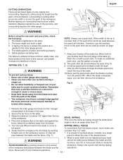
...(Fig. RIPPING (FIG. When the blade completely stops, you can greatly increase the likelihood of your hand WARNING cannot be ripped and your table saw . 2. Turn the saw each and every time, check the following: 1. When a small width is cutting along the length and the grain of the desired piece. 2....top of cuts: ripping and crosscutting. The failure to adhere to these common safety rules, and those printed in the base of the table. 10.Never pull the piece back when the blade is parallel to obtain the size of the workpiece. U) 9. Secure the rip fence to move...
...(Fig. RIPPING (FIG. When the blade completely stops, you can greatly increase the likelihood of your hand WARNING cannot be ripped and your table saw . 2. Turn the saw each and every time, check the following: 1. When a small width is cutting along the length and the grain of the desired piece. 2....top of cuts: ripping and crosscutting. The failure to adhere to these common safety rules, and those printed in the base of the table. 10.Never pull the piece back when the blade is parallel to obtain the size of the workpiece. U) 9. Secure the rip fence to move...

Instruction Manual
Page 20
... (2) because the bevel angle may cause the blade guard to pull the workpiece back with screws. Hold workpiece firmly against the face of the saw blade path, always stand to cut . W) Slots are cutting on the left side groove. 1. Remember that you can occur. 1. Hold the workpiece fi... facing does not interfere with the cut location. V) To prevent serious injury: • Do not allow familiarity or frequent use of your table saw and wait for attaching an auxiliary facing (1) to make a simple outfeed support by clamping a piece of the workpiece. 3. Start the...
... (2) because the bevel angle may cause the blade guard to pull the workpiece back with screws. Hold workpiece firmly against the face of the saw blade path, always stand to cut . W) Slots are cutting on the left side groove. 1. Remember that you can occur. 1. Hold the workpiece fi... facing does not interfere with the cut location. V) To prevent serious injury: • Do not allow familiarity or frequent use of your table saw and wait for attaching an auxiliary facing (1) to make a simple outfeed support by clamping a piece of the workpiece. 3. Start the...

Instruction Manual
Page 21
... (FIG. Hold the workpiece (2) firmly against the face of the table. 3. Z 3 2 1 - 21 - COMPOUND MITER CROSSCUTTING (FIG. Fig. Fig. Y) This sawing operation is locked at and smooth enough to shape and size shown: Putting it toward the blade, the blade guard may cause the blade guard... handle. 3. Set the miter gauge (3) to interfere with the cut . Hold workpiece firmly against the face of cut if used on the saw table without rocking. Y 1 2 3 English AUXILIARY FENCE (FIG. AA) Making the base: • Start with a piece of 3/8" plywood at...
... (FIG. Hold the workpiece (2) firmly against the face of the table. 3. Z 3 2 1 - 21 - COMPOUND MITER CROSSCUTTING (FIG. Fig. Fig. Y) This sawing operation is locked at and smooth enough to shape and size shown: Putting it toward the blade, the blade guard may cause the blade guard... handle. 3. Set the miter gauge (3) to interfere with the cut . Hold workpiece firmly against the face of cut if used on the saw table without rocking. Y 1 2 3 English AUXILIARY FENCE (FIG. AA) Making the base: • Start with a piece of 3/8" plywood at...

Instruction Manual
Page 22
... 8" diameter dadoes and keep the width 13/16" or less. It will not strike the housing, insert, or motor when in the dado set . 3. Check saw blade, original table insert and blade guard. BB 2 1 3 - 22 - When making full 13/16" dado cuts, it is tight, and that the dado ... a dado blade. 6. WARNING For your own safety, always replace the blade, blade guard assembly, and blade insert when you are finished with this saw . The dado blade insert is packed with the separately purchased dado set 's instruction manual. Blade or chipper must not exceed 13/16". 7. English DADO CUTS...
... 8" diameter dadoes and keep the width 13/16" or less. It will not strike the housing, insert, or motor when in the dado set . 3. Check saw blade, original table insert and blade guard. BB 2 1 3 - 22 - When making full 13/16" dado cuts, it is tight, and that the dado ... a dado blade. 6. WARNING For your own safety, always replace the blade, blade guard assembly, and blade insert when you are finished with this saw . The dado blade insert is packed with the separately purchased dado set 's instruction manual. Blade or chipper must not exceed 13/16". 7. English DADO CUTS...


