
Instruction Manual
Page 3
.... Always confirm that has not been specifically recommended by installing locks on the doors and on the power tool and in the moving parts. Avoid injuries by the failure to observe basic safety rules or precautions. Always keep the work area well lighted. 5. Always unplug... unattended tools and keep the work place tamper-proof by HITACHI. English IMPORTANT SAFETY INFORMATION Read and understand all of the safety precautions, warnings and operating instructions in death or serious injury. NOTE ...
.... Always confirm that has not been specifically recommended by installing locks on the doors and on the power tool and in the moving parts. Avoid injuries by the failure to observe basic safety rules or precautions. Always keep the work area well lighted. 5. Always unplug... unattended tools and keep the work place tamper-proof by HITACHI. English IMPORTANT SAFETY INFORMATION Read and understand all of the safety precautions, warnings and operating instructions in death or serious injury. NOTE ...

Instruction Manual
Page 4
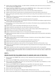
...Always follow instructions for lubricating the tool and for additional safety and wear a dust mask if the cutting operation produces dust. 10. ALWAYS CHECK FOR DAMAGED PARTS BEFORE USING THE TOOL. NEVER LEAVE THE TOOL RUNNING WHILE UNATTENDED. Do not leave tool until it . 4 Always return the...rules and operating instructions for long workpieces that they will fit in use outboard stands to assure that overhang the table of the slide compound saw. 25. ALWAYS USE RECOMMENDED ACCESSORIES ONLY WHEN OPERATING THIS TOOL. Prevent serious injury by not tipping the tool and by not ...
...Always follow instructions for lubricating the tool and for additional safety and wear a dust mask if the cutting operation produces dust. 10. ALWAYS CHECK FOR DAMAGED PARTS BEFORE USING THE TOOL. NEVER LEAVE THE TOOL RUNNING WHILE UNATTENDED. Do not leave tool until it . 4 Always return the...rules and operating instructions for long workpieces that they will fit in use outboard stands to assure that overhang the table of the slide compound saw. 25. ALWAYS USE RECOMMENDED ACCESSORIES ONLY WHEN OPERATING THIS TOOL. Prevent serious injury by not tipping the tool and by not ...
Instruction Manual
Page 5
...moving parts, including the blade, while the saw at once, if you fully understand the operating instructions contained in use of oil and grease. When replacing the saw blade. 16. Always shut off the power and wait for use on the supporting surface. During miter or bevel cutting...hair is in the proper place before attempting any moving machinery. 6. Never use of the slide compound saw blade. 7. Always confirm that overhang the table of the saw blade away from the operator. 10. Always operate the tool after you are being utilized, if necessary, before starting the tool....
...moving parts, including the blade, while the saw at once, if you fully understand the operating instructions contained in use of oil and grease. When replacing the saw blade. 16. Always shut off the power and wait for use on the supporting surface. During miter or bevel cutting...hair is in the proper place before attempting any moving machinery. 6. Never use of the slide compound saw blade. 7. Always confirm that overhang the table of the saw blade away from the operator. 10. Always operate the tool after you are being utilized, if necessary, before starting the tool....
Instruction Manual
Page 6
...conducted only by a Hitachi authorized service center. 6 Never use in place. 4. When slide cutting, never pull the handle toward the operator, since this saw blade to stop . 18. Never use only identical replacement parts. Always wear eye protection when using the tool. 10. Saw blade diameter is cracked... blade or servicing. 8. Never operate the saw . 5. Never clean plastic components with the slide compound saw unless all the blade guards are in POWER TOOL while your limbs inside of the saw blade. 6. No load speed is 3800/min. 10. English 9. Never lock the safety cover;...
...conducted only by a Hitachi authorized service center. 6 Never use in place. 4. When slide cutting, never pull the handle toward the operator, since this saw blade to stop . 18. Never use only identical replacement parts. Always wear eye protection when using the tool. 10. Saw blade diameter is cracked... blade or servicing. 8. Never operate the saw . 5. Never clean plastic components with the slide compound saw unless all the blade guards are in POWER TOOL while your limbs inside of the saw blade. 6. No load speed is 3800/min. 10. English 9. Never lock the safety cover;...
Instruction Manual
Page 7
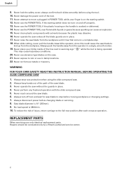
... the cord. Although this system has no external grounding, you must still follow these precautions: * Only HITACHI AUTHORIZED SERVICE CENTER should disassemble or assemble this power tool, HITACHI has adopted a double insulation design. English USE PROPER EXTENSION CORD Make sure your product will cause a ... on the nameplate. Ampere More Than Rating Not More Than 0 - 6 6 - 10 10 - 12 12 - 16 MINIMUM GAGE FOR CORD SETS Total Length of this power tool, and only genuine HITACHI replacement parts should be sure to use one heavy enough to the power supply from the outer frame...
... the cord. Although this system has no external grounding, you must still follow these precautions: * Only HITACHI AUTHORIZED SERVICE CENTER should disassemble or assemble this power tool, HITACHI has adopted a double insulation design. English USE PROPER EXTENSION CORD Make sure your product will cause a ... on the nameplate. Ampere More Than Rating Not More Than 0 - 6 6 - 10 10 - 12 12 - 16 MINIMUM GAGE FOR CORD SETS Total Length of this power tool, and only genuine HITACHI replacement parts should be sure to use one heavy enough to the power supply from the outer frame...

Instruction Manual
Page 8
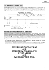
NAME OF PARTS MODEL C10FSH/MODEL C10FSB Dust Bag Hinge Gear Case Motor Head Moter Handle Spindle Cover Holder (A) Saw Blade Indicator (For right bevel scale) Leser Marker (Only C10FSH) Vise Assembly Safety Cover Rotation Direction Fence (A) Indicator (For miter scale) Table Insert Fence (B) Sub ...Fence Fig. 1 Turntable Lever Side Handle Trigger Switch 5mm Screw Nameplate Spindle Lock Belt Cover Switch (for Laser marker) (Only C10FSH) Locking Pin Adjuster (Only C10FSH) (for Laser marker) Slide Securing Knob Indicator (for left bevel ...
NAME OF PARTS MODEL C10FSH/MODEL C10FSB Dust Bag Hinge Gear Case Motor Head Moter Handle Spindle Cover Holder (A) Saw Blade Indicator (For right bevel scale) Leser Marker (Only C10FSH) Vise Assembly Safety Cover Rotation Direction Fence (A) Indicator (For miter scale) Table Insert Fence (B) Sub ...Fence Fig. 1 Turntable Lever Side Handle Trigger Switch 5mm Screw Nameplate Spindle Lock Belt Cover Switch (for Laser marker) (Only C10FSH) Locking Pin Adjuster (Only C10FSH) (for Laser marker) Slide Securing Knob Indicator (for left bevel ...

Instruction Manual
Page 11
Installation 5-29/32"(150mm) Base 5/16" (8mm) Bolt English 10-13/32" (264mm) 1" (25mm) thick bench 11/32" (9mm) 3 Holes 11-13/16" (300mm) Work Bench 5/16" (8mm) Nut Fig. 4 Attach the power tool to a ... be at least 1-9/16" (40mm) plus the thickness of the locking pin is prepared for carrying and storage only. Adjust the holder until its main parts are optional accessories.) Attach the dust bag and vise assembly as indicated in accordance with the supplied 10mm box wrench. The lock position of the...
Installation 5-29/32"(150mm) Base 5/16" (8mm) Bolt English 10-13/32" (264mm) 1" (25mm) thick bench 11/32" (9mm) 3 Holes 11-13/16" (300mm) Work Bench 5/16" (8mm) Nut Fig. 4 Attach the power tool to a ... be at least 1-9/16" (40mm) plus the thickness of the locking pin is prepared for carrying and storage only. Adjust the holder until its main parts are optional accessories.) Attach the dust bag and vise assembly as indicated in accordance with the supplied 10mm box wrench. The lock position of the...
Instruction Manual
Page 16
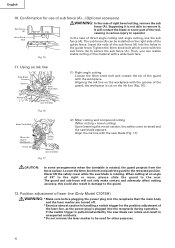
...) Fig. 17 (2) Miter cutting and compound cutting (Miter cutting + bevel cutting) Upon lowering the motor section, the safety cover is raised and the saw blade appears. CAUTION: In some part of the tool, causing... receptacle during operation. Never lift the safety cover while the saw blade is pulled inadvertently, the saw blade (Fig. 17). English 10. Supposing it , It will not only make contact and...slide the guard to remove it is not able to the rear. If the switch trigger is rotating. Tighten the 6mm knob bolt which come with the workpiece. Align the ink line with the saw...
...) Fig. 17 (2) Miter cutting and compound cutting (Miter cutting + bevel cutting) Upon lowering the motor section, the safety cover is raised and the saw blade appears. CAUTION: In some part of the tool, causing... receptacle during operation. Never lift the safety cover while the saw blade is pulled inadvertently, the saw blade (Fig. 17). English 10. Supposing it , It will not only make contact and...slide the guard to remove it is not able to the rear. If the switch trigger is rotating. Tighten the 6mm knob bolt which come with the workpiece. Align the ink line with the saw...
Instruction Manual
Page 28
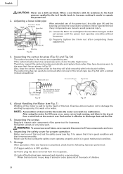
... is effective to wash oil or water. Re-tighten screws on any components are expendable parts. If the carbon brushes become loose due to be removed after completing these adjustment. Exercise... dry place out of the reach of this tool. English CAUTION: Never use a dull saw blade is dull, its resistance to the hand pressure applied by exposing it to discharge dust ...and the like inside the motor can result in a malfunction. Slide Pipe (A) Holder (A) Bushing Fig. 52 3. Fig. 54 4. About Handling the Motor (see Fig. ...
... is effective to wash oil or water. Re-tighten screws on any components are expendable parts. If the carbon brushes become loose due to be removed after completing these adjustment. Exercise... dry place out of the reach of this tool. English CAUTION: Never use a dull saw blade is dull, its resistance to the hand pressure applied by exposing it to discharge dust ...and the like inside the motor can result in a malfunction. Slide Pipe (A) Holder (A) Bushing Fig. 52 3. Fig. 54 4. About Handling the Motor (see Fig. ...

Instruction Manual
Page 29
...Poly-V-Belt Poly-V-Belt Pulley (A) The power of machine oil is transmitted to the saw blade by an AUTHORIZED HITACHI POWER TOOL REPAIR CENTER ONLY. SERVICE AND REPAIRS All quality power tools will be protected, all 10 teeth of the pulley (A) and pulley (B). Fig. 55 9. After replacing, make... with a damp, soapy cloth. Lubrication Lubricate the following sliding surfaces once a month to chips and the like adhered onto the window of the safety cover with a new one. To assure that only authorized replacement parts will be used and that the double insulation system will ...
...Poly-V-Belt Poly-V-Belt Pulley (A) The power of machine oil is transmitted to the saw blade by an AUTHORIZED HITACHI POWER TOOL REPAIR CENTER ONLY. SERVICE AND REPAIRS All quality power tools will be protected, all 10 teeth of the pulley (A) and pulley (B). Fig. 55 9. After replacing, make... with a damp, soapy cloth. Lubrication Lubricate the following sliding surfaces once a month to chips and the like adhered onto the window of the safety cover with a new one. To assure that only authorized replacement parts will be used and that the double insulation system will ...

Parts List
Page 1
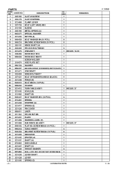
E933 ELECTRIC TOOL PARTS LIST SLIDE COMPOUND SAW Model C 10FSB 2004 • 2 • 13 (E2) 1 2 3 4 56 7 40 41 8 9 10 11 12 14 15 16 13 17 18 19 20 21 22 23 24 25 26 27 28 29 30 29 31 32 33 9 10 35 34 10 9 36 37 38 39 601 603 602 618 604 605 602 606 607 10 608 9 42 43 9 10 44 45 46 48 47 10 9 56 609 57 610 58 611 59 612 22 52 49 60 613 51 50 623 622 621 619 624 620 625 626 631 627 628 629 628 630 614 54 55 617 53A 616 615 618 Hitachi Power Tools LIST NO.
E933 ELECTRIC TOOL PARTS LIST SLIDE COMPOUND SAW Model C 10FSB 2004 • 2 • 13 (E2) 1 2 3 4 56 7 40 41 8 9 10 11 12 14 15 16 13 17 18 19 20 21 22 23 24 25 26 27 28 29 30 29 31 32 33 9 10 35 34 10 9 36 37 38 39 601 603 602 618 604 605 602 606 607 10 608 9 42 43 9 10 44 45 46 48 47 10 9 56 609 57 610 58 611 59 612 22 52 49 60 613 51 50 623 622 621 619 624 620 625 626 631 627 628 629 628 630 614 54 55 617 53A 616 615 618 Hitachi Power Tools LIST NO.
Parts List
Page 4
... 321-339 LEVER SHAFT 1 50 321-338 LEVER 1 51 321-340 SPRING (D) 1 --- 4 --- * ALTERNATIVE PARTS C 10FSB 2 -- 04 CODE NO. 1 305-180 DESCRIPTION CLUTCH SCREW NO. SCREW M6X25 (10 PCS.) 1 40 998-818 TABLE INSERT 2 41 949-258 MACHINE SCREW M6X20 (10 PCS.) 6 42 321-329 INDICATOR 1 43 321-342 SPACER (A) 1 44 321-341 SHAFT...
... 321-339 LEVER SHAFT 1 50 321-338 LEVER 1 51 321-340 SPRING (D) 1 --- 4 --- * ALTERNATIVE PARTS C 10FSB 2 -- 04 CODE NO. 1 305-180 DESCRIPTION CLUTCH SCREW NO. SCREW M6X25 (10 PCS.) 1 40 998-818 TABLE INSERT 2 41 949-258 MACHINE SCREW M6X20 (10 PCS.) 6 42 321-329 INDICATOR 1 43 321-342 SPACER (A) 1 44 321-341 SHAFT...
Parts List
Page 5
...-206 CAUTION LABEL (A) 1 99 321-375 HOLDER (A) 1 100 949-686 ROLL PIN D6X40 (10 PCS.) 2 101 321-329 INDICATOR 2 102 303-409 NYLOCK BOLT M8X25 1 103 307-956 ... 312-672 BASE RUBBER 4 55 315-210 SCALE (A) 1 * 56 949-616 BOLT M6X25 (10 PCS.) 1 EXCEPT FOR USA, CAN, AUS, NZL * 57 987-860 SEAL LOCK HEX. ...10 PCS.) 4 * 74 322-198 HINGE (B) ASS'Y 1 INCLUD. 89 FOR AUS, NZL * 74 322-653 HINGE (B) ASS'Y 1 INCLUD. 89 * 74 321-391 HINGE (B) ASS'Y 1 INCLUD. 89 FOR USA, CAN 75 996-276 SLEEVE 1 76 321-332 SPRING 1 77 961-554 HEX. CODE NO. 52 321-345 FENCE (A) DESCRIPTION NO. PARTS...
...-206 CAUTION LABEL (A) 1 99 321-375 HOLDER (A) 1 100 949-686 ROLL PIN D6X40 (10 PCS.) 2 101 321-329 INDICATOR 2 102 303-409 NYLOCK BOLT M8X25 1 103 307-956 ... 312-672 BASE RUBBER 4 55 315-210 SCALE (A) 1 * 56 949-616 BOLT M6X25 (10 PCS.) 1 EXCEPT FOR USA, CAN, AUS, NZL * 57 987-860 SEAL LOCK HEX. ...10 PCS.) 4 * 74 322-198 HINGE (B) ASS'Y 1 INCLUD. 89 FOR AUS, NZL * 74 322-653 HINGE (B) ASS'Y 1 INCLUD. 89 * 74 321-391 HINGE (B) ASS'Y 1 INCLUD. 89 FOR USA, CAN 75 996-276 SLEEVE 1 76 321-332 SPRING 1 77 961-554 HEX. CODE NO. 52 321-345 FENCE (A) DESCRIPTION NO. PARTS...

Parts List
Page 6
...USA, CAN 4 3 FOR USA, CAN 1 INCLUD. 134, 146 1 INCLUD. 134, 146 FOR USA, CAN 2 INCLUD. 134, 146 FOR USA, CAN --- 6 --- * ALTERNATIVE PARTS C 10FSB 2 -- 04 SCREW M6X25 (10 PCS.) BOLT COVER CORD ARMOR D10.1 1 EXCEPT FOR USA, CAN, AUS, NZL 1 EXCEPT FOR USA, CAN, AUS, NZL 1 122 937-631 CORD CLIP...) D5X25 (BLACK) 3 126 321-355 SHEET 1 * 127 321-354 CONTROLLER 100V-120V 1 * 127 322-200 CONTROLLER 220V-240V 1 128 930-804 TERMINAL M4.0 (10 PCS.) 1 129 321-393 HANDLE (R) 1 130 301-653 131 880-734 132 321-383 TAPPING SCREW (W/FLANGE) D4X20 (BLACK) 6 MACHINE SCREW (W/WASHERS) M5X25 (BLACK...
...USA, CAN 4 3 FOR USA, CAN 1 INCLUD. 134, 146 1 INCLUD. 134, 146 FOR USA, CAN 2 INCLUD. 134, 146 FOR USA, CAN --- 6 --- * ALTERNATIVE PARTS C 10FSB 2 -- 04 SCREW M6X25 (10 PCS.) BOLT COVER CORD ARMOR D10.1 1 EXCEPT FOR USA, CAN, AUS, NZL 1 EXCEPT FOR USA, CAN, AUS, NZL 1 122 937-631 CORD CLIP...) D5X25 (BLACK) 3 126 321-355 SHEET 1 * 127 321-354 CONTROLLER 100V-120V 1 * 127 322-200 CONTROLLER 220V-240V 1 128 930-804 TERMINAL M4.0 (10 PCS.) 1 129 321-393 HANDLE (R) 1 130 301-653 131 880-734 132 321-383 TAPPING SCREW (W/FLANGE) D4X20 (BLACK) 6 MACHINE SCREW (W/WASHERS) M5X25 (BLACK...
Parts List
Page 7
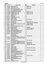
...10 PCS.) 1 164 606-ZZM BALL BEARING 606ZZC2PS2L 1 165 949-455 SPRING WASHER M6 (10 PCS.) 1 166 949-425 WASHER M6 (10 PCS.) 1 167 HITACHI... LABEL 1 168 WARNING LABEL (G) 1 FOR USA, CAN 169 304-043 MACHINE SCREW (W/WASHERS) M4X10 (BLACK) 1 170 877-839 SEAL LOCK HEX. DESCRIPTION NO. BOLT M5X10 1 171 321-384 GEAR CASE 1 172 WARNING LABEL (G) 1 FOR USA, CAN * 173 322-443 TCT SAW... BLADE 255MM-D30 HOLE-NT40 1 * 173 TCT SAW BLADE 262MM-D25.4 HOLE-NT60 1 FOR AUS, NZL * 173 310-878 TCT SAW...10 PCS.) 2 179 949-454 SPRING WASHER M5 (10... M4X10 (10 PCS.) ...
...10 PCS.) 1 164 606-ZZM BALL BEARING 606ZZC2PS2L 1 165 949-455 SPRING WASHER M6 (10 PCS.) 1 166 949-425 WASHER M6 (10 PCS.) 1 167 HITACHI... LABEL 1 168 WARNING LABEL (G) 1 FOR USA, CAN 169 304-043 MACHINE SCREW (W/WASHERS) M4X10 (BLACK) 1 170 877-839 SEAL LOCK HEX. DESCRIPTION NO. BOLT M5X10 1 171 321-384 GEAR CASE 1 172 WARNING LABEL (G) 1 FOR USA, CAN * 173 322-443 TCT SAW... BLADE 255MM-D30 HOLE-NT40 1 * 173 TCT SAW BLADE 262MM-D25.4 HOLE-NT60 1 FOR AUS, NZL * 173 310-878 TCT SAW...10 PCS.) 2 179 949-454 SPRING WASHER M5 (10... M4X10 (10 PCS.) ...
Parts List
Page 8
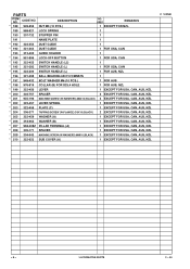
DESCRIPTION NO. CODE NO. PARTS ITEM NO. USED REMARKS * 188 949-555 NUT M5 (10 PCS.) 1 EXCEPT FOR NZL 189 988-821 LOCK SPRING 1 190 307-732 STOPPER PIN 1 191 NAME PLATE 1 * 192 ... FOR USA, CAN * 195 322-209 SWITCH HANDLE (L) 1 FOR AUS, NZL 196 321-398 BALL BEARING 6201VVCMNS7S 1 * 197 949-432 BOLT WASHER M6 (10 PCS.) 1 FOR AUS * 198 976-819 COLLAR (B) FOR D25.4 HOLE 1 FOR AUS, NZL * 199 322-456 LEVER 1 EXCEPT FOR USA, CAN, ... EXCEPT FOR USA, CAN, AUS, NZL * 210 322-623 SUB COVER (A) 1 EXCEPT FOR USA, CAN, AUS, NZL C 10FSB --- 8 --- * ALTERNATIVE PARTS 2 -- 04
DESCRIPTION NO. CODE NO. PARTS ITEM NO. USED REMARKS * 188 949-555 NUT M5 (10 PCS.) 1 EXCEPT FOR NZL 189 988-821 LOCK SPRING 1 190 307-732 STOPPER PIN 1 191 NAME PLATE 1 * 192 ... FOR USA, CAN * 195 322-209 SWITCH HANDLE (L) 1 FOR AUS, NZL 196 321-398 BALL BEARING 6201VVCMNS7S 1 * 197 949-432 BOLT WASHER M6 (10 PCS.) 1 FOR AUS * 198 976-819 COLLAR (B) FOR D25.4 HOLE 1 FOR AUS, NZL * 199 322-456 LEVER 1 EXCEPT FOR USA, CAN, ... EXCEPT FOR USA, CAN, AUS, NZL * 210 322-623 SUB COVER (A) 1 EXCEPT FOR USA, CAN, AUS, NZL C 10FSB --- 8 --- * ALTERNATIVE PARTS 2 -- 04
Parts List
Page 9
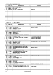
... MOLDING STOPPER HOLDER 1 618 321-374 CROWN MOLDING STOPPER (L) ASS'Y 1 INCLUD. 614-617 619 974-561 STOPPER 1 620 949-404 WING BOLT M6X20 (10 PCS.) 1 621 321-390 CROWN MOLDING STOPPER HOLDER 1 622 CROWN HOLDING STOPPER (R) 1 623 301-806 WING BOLT M6X15 1 624 321-373 CROWN MOLDING ...321-553 GUIDE ASS'Y 1 INCLUD. 614, 619, 620, 625-630 * 632 322-444 TCT SAW BLADE 255MM-D30 HOLE-NT72 1 * 632 307-713 TCT SAW BLADE 255MM-D25.4 HOLE-NT72 1 FOR AUS, NZL 2 -- 04 * ALTERNATIVE PARTS --- 9 --- STANDARD ACCESSORIES ITEM NO. DESCRIPTION 501 940-543 BOX WRENCH 10MM 502 998-845 ...
... MOLDING STOPPER HOLDER 1 618 321-374 CROWN MOLDING STOPPER (L) ASS'Y 1 INCLUD. 614-617 619 974-561 STOPPER 1 620 949-404 WING BOLT M6X20 (10 PCS.) 1 621 321-390 CROWN MOLDING STOPPER HOLDER 1 622 CROWN HOLDING STOPPER (R) 1 623 301-806 WING BOLT M6X15 1 624 321-373 CROWN MOLDING ...321-553 GUIDE ASS'Y 1 INCLUD. 614, 619, 620, 625-630 * 632 322-444 TCT SAW BLADE 255MM-D30 HOLE-NT72 1 * 632 307-713 TCT SAW BLADE 255MM-D25.4 HOLE-NT72 1 FOR AUS, NZL 2 -- 04 * ALTERNATIVE PARTS --- 9 --- STANDARD ACCESSORIES ITEM NO. DESCRIPTION 501 940-543 BOX WRENCH 10MM 502 998-845 ...


