
Operating Instructions
Page 5
... provided with care when dismounting and mounting it slides smoothly before using the tool. 10. Never leave the POWER TOOL unattended without them would be thrust form the table and cause bodily harm. 10. Never use on the supporting surface. Never remove any maintenance or adjustments. 9. ...the rpm rating of the new blade is free of the compound saw blade. 11. Never damage the power cord of the saw at once, if you have taken any medications, or have consumed any abnormality whatsoever. 6. During miter or bevel cutting, always wait for applications not specified in ...
... provided with care when dismounting and mounting it slides smoothly before using the tool. 10. Never leave the POWER TOOL unattended without them would be thrust form the table and cause bodily harm. 10. Never use on the supporting surface. Never remove any maintenance or adjustments. 9. ...the rpm rating of the new blade is free of the compound saw blade. 11. Never damage the power cord of the saw at once, if you have taken any medications, or have consumed any abnormality whatsoever. 6. During miter or bevel cutting, always wait for applications not specified in ...

Operating Instructions
Page 8
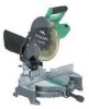
...from those on your own power tool. NAME OF PARTS MODEL C10FCH/MODEL C10FCE Dust Bag Motor Head Gear Case Handle Motor Saw Blade Laser Marker (Only C10FCH) Vise Assembly Fence (B) Turntable Lower Guard Rotation Direction Indicator (B) (For bevel scale) Fence (A) Table Insert... Indicator (A) (For miter scale) Lever Side Handle Fig. 1 Switch (for Laser marker) (Only C10FCH) Trigger Switch Nameplate Base Locking Pin Clamp Lever Holder (B) Fig. ...
...from those on your own power tool. NAME OF PARTS MODEL C10FCH/MODEL C10FCE Dust Bag Motor Head Gear Case Handle Motor Saw Blade Laser Marker (Only C10FCH) Vise Assembly Fence (B) Turntable Lower Guard Rotation Direction Indicator (B) (For bevel scale) Fence (A) Table Insert... Indicator (A) (For miter scale) Lever Side Handle Fig. 1 Switch (for Laser marker) (Only C10FCH) Trigger Switch Nameplate Base Locking Pin Clamp Lever Holder (B) Fig. ...
Operating Instructions
Page 9
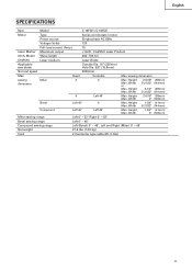
English SPECIFICATIONS Item Model C 10FCH / C 10FCE Motor Type Series commutator motor Power source Single-phase AC 60Hz Voltage (Volts) 120 Full-load current (Amp) 15 Laser Marker Maximum output
English SPECIFICATIONS Item Model C 10FCH / C 10FCE Motor Type Series commutator motor Power source Single-phase AC 60Hz Voltage (Volts) 120 Full-load current (Amp) 15 Laser Marker Maximum output

Operating Instructions
Page 17
... of alignment, or with the right hand side for compound cutting. If the handle is secured on the left side of the saw blade might then contact the clamp or vise that the miter scale and the tip of the saw blade. 6. When stopping the bevel cutting operation halfway,...Never remove the side handle; Never rotate the table to secure the turntable in 4 and 5 above. Miter cutting procedures (1) Loosen the side handle and push the lever for compound cutting, because the saw blade. For maximum dimensions for bevel scale) Clamp Lever Tighten Loosen Fig. 23 WARNING: When the workpiece...
... of alignment, or with the right hand side for compound cutting. If the handle is secured on the left side of the saw blade might then contact the clamp or vise that the miter scale and the tip of the saw blade. 6. When stopping the bevel cutting operation halfway,...Never remove the side handle; Never rotate the table to secure the turntable in 4 and 5 above. Miter cutting procedures (1) Loosen the side handle and push the lever for compound cutting, because the saw blade. For maximum dimensions for bevel scale) Clamp Lever Tighten Loosen Fig. 23 WARNING: When the workpiece...

Operating Instructions
Page 19
... vise (B) (Optional accessory) can be shown in position. Fence After adjusting the height, firmly tighten the 6mm wing bolt; The main body or saw blade may do so, loosen the 6mm knob bolt and move the crown molding vise ass'y to securely attach the crown molding in Fig. 30... crown molding Stoppers according to secure the crown molding Stoppers. 19 Head Bevel Angle Scale 4 1 Fence Miter Angle Scale Turntable Fig. 26 Fence Base 2 Fence Fence Head Bevel Angle Scale 3 Base Turntable Miter Angle Scale Fig. 27 English Table on Base Table on either the left fence (Fence (B)) or the...
... vise (B) (Optional accessory) can be shown in position. Fence After adjusting the height, firmly tighten the 6mm wing bolt; The main body or saw blade may do so, loosen the 6mm knob bolt and move the crown molding vise ass'y to securely attach the crown molding in Fig. 30... crown molding Stoppers according to secure the crown molding Stoppers. 19 Head Bevel Angle Scale 4 1 Fence Miter Angle Scale Turntable Fig. 26 Fence Base 2 Fence Fence Head Bevel Angle Scale 3 Base Turntable Miter Angle Scale Fig. 27 English Table on Base Table on either the left fence (Fence (B)) or the...


