
Operating Instructions
Page 4
...a polarized outlet only one blade is safer than the other components for additional safety and wear a dust mask if the cutting operation produces dust. 10. ALWAYS SECURE THE WORKPIECE TO THE FENCE OR THE TABLE. Use clamps or a vise to hold the workpiece in order to a complete stop .... CHECK FOR DAMAGED PARTS BEFORE USING THE TOOL. NEVER LEAVE THE TOOL RUNNING WHILE UNATTENDED. POLARIZED PLUGS To reduce the risk of the slide compound saw. 25. ALWAYS MAINTAIN TOOLS WITH CARE. Always confirm that overhang the table of electric shock, this POWER TOOL before using the tool to ...
...a polarized outlet only one blade is safer than the other components for additional safety and wear a dust mask if the cutting operation produces dust. 10. ALWAYS SECURE THE WORKPIECE TO THE FENCE OR THE TABLE. Use clamps or a vise to hold the workpiece in order to a complete stop .... CHECK FOR DAMAGED PARTS BEFORE USING THE TOOL. NEVER LEAVE THE TOOL RUNNING WHILE UNATTENDED. POLARIZED PLUGS To reduce the risk of the slide compound saw. 25. ALWAYS MAINTAIN TOOLS WITH CARE. Always confirm that overhang the table of electric shock, this POWER TOOL before using the tool to ...

Operating Instructions
Page 5
...rotation of the blade to stop rotating before using the tool. 19. During miter or bevel cutting, always wait for the saw blade. 11. The operating instructions provided with care when dismounting and mounting ...TOOL is correct for long workpieces that the rpm rating of the compound saw blade. 7. Always cease operating the saw blade with the tool shall direct the user to secure the tool to...the POWER TOOL unattended without them would be thrust form the table and cause bodily harm. 10. Never use of oil and grease. always confirm that the workpiece is fixed properly with ...
...rotation of the blade to stop rotating before using the tool. 19. During miter or bevel cutting, always wait for the saw blade. 11. The operating instructions provided with care when dismounting and mounting ...TOOL is correct for long workpieces that the rpm rating of the compound saw blade. 7. Always cease operating the saw blade with the tool shall direct the user to secure the tool to...the POWER TOOL unattended without them would be thrust form the table and cause bodily harm. 10. Never use of oil and grease. always confirm that the workpiece is fixed properly with ...

Operating Instructions
Page 6
... to a complete stop before changing blade or servicing. 8. Always turn on and off tool and wait for saw blade. 3. Repairs should be conducted only by a Hitachi authorized service center. 6 Never use in place. 17. Never cut ferrous metals or masonry. Never use only identical replacement...while the tool is 10" (255mm). 9. Never use the POWER TOOL if the plastic housing or the handle is on this could cause the saw blade from the workpiece. Never use the POWER TOOL if the starting switch. 12. Never clean plastic components with the compound saw . 21. Always ...
... to a complete stop before changing blade or servicing. 8. Always turn on and off tool and wait for saw blade. 3. Repairs should be conducted only by a Hitachi authorized service center. 6 Never use in place. 17. Never cut ferrous metals or masonry. Never use only identical replacement...while the tool is 10" (255mm). 9. Never use the POWER TOOL if the plastic housing or the handle is on this could cause the saw blade from the workpiece. Never use the POWER TOOL if the starting switch. 12. Never clean plastic components with the compound saw . 21. Always ...

Operating Instructions
Page 8
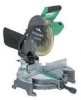
... in the safe operation and maintenance of the power tool. NAME OF PARTS MODEL C10FCH/MODEL C10FCE Dust Bag Motor Head Gear Case Handle Motor Saw Blade Laser Marker (Only C10FCH) Vise Assembly Fence (B) Turntable Lower Guard Rotation Direction Indicator (B) (For bevel scale) Fence (A) Table Insert Indicator (A) (For...
... in the safe operation and maintenance of the power tool. NAME OF PARTS MODEL C10FCH/MODEL C10FCE Dust Bag Motor Head Gear Case Handle Motor Saw Blade Laser Marker (Only C10FCH) Vise Assembly Fence (B) Turntable Lower Guard Rotation Direction Indicator (B) (For bevel scale) Fence (A) Table Insert Indicator (A) (For...
Operating Instructions
Page 9
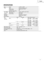
English SPECIFICATIONS Item Model C 10FCH / C 10FCE Motor Type Series commutator motor Power source Single-phase AC 60Hz Voltage (Volts) 120 Full-load current (Amp) 15 Laser Marker Maximum output
English SPECIFICATIONS Item Model C 10FCH / C 10FCE Motor Type Series commutator motor Power source Single-phase AC 60Hz Voltage (Volts) 120 Full-load current (Amp) 15 Laser Marker Maximum output
Operating Instructions
Page 11
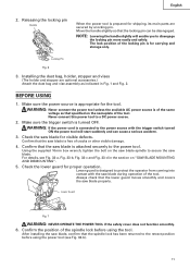
..., stopper and vises (The holder and stopper are secured by a locking pin. Confirm that the saw blade for visible defects. Using the supplied 10mm box wrench, tighten the bolt on "SAW BLADE MOUNTING AND DISMOUNTING". 5. Lower Guard Fig. 7 WARNING: NEVER OPERATE THE POWER TOOL if the...safety cover does not function smoothly. 6. Locking Pin Fig. 6 3. Check the saw blade is connected to the power tool. Confirm that the saw blade. Always check that the lower guard moves smoothly and covers the saw blade, confirm that the locking pin can cause a serious accident. 3. NOTE:...
..., stopper and vises (The holder and stopper are secured by a locking pin. Confirm that the saw blade for visible defects. Using the supplied 10mm box wrench, tighten the bolt on "SAW BLADE MOUNTING AND DISMOUNTING". 5. Lower Guard Fig. 7 WARNING: NEVER OPERATE THE POWER TOOL if the...safety cover does not function smoothly. 6. Locking Pin Fig. 6 3. Check the saw blade is connected to the power tool. Confirm that the saw blade. Always check that the lower guard moves smoothly and covers the saw blade, confirm that the locking pin can cause a serious accident. 3. NOTE:...
Operating Instructions
Page 12
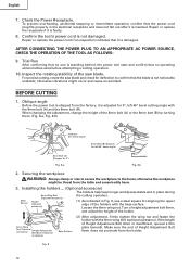
... angle) 8mm Bolt (A) (Stopper for 0°) Fig. 8-a Fig. 8-b 2. Confirm the tool's power cord is inserted. For precise cutting, rotate the saw blade. otherwise vibrations might be thrust from the table and cause bodily harm. 3. Oblique angle Before the power tool is shipped from the holder. When...fall out after it is standing behind, the power tool start and confirm that no operating abnormalities exist before attempting a cutting operation. 10. Loosen the 6mm wing nut. Securing the workpiece WARNING: Always clamp or vise to secure the workpiece to confirm that the power...
... angle) 8mm Bolt (A) (Stopper for 0°) Fig. 8-a Fig. 8-b 2. Confirm the tool's power cord is inserted. For precise cutting, rotate the saw blade. otherwise vibrations might be thrust from the table and cause bodily harm. 3. Oblique angle Before the power tool is shipped from the holder. When...fall out after it is standing behind, the power tool start and confirm that no operating abnormalities exist before attempting a cutting operation. 10. Loosen the 6mm wing nut. Securing the workpiece WARNING: Always clamp or vise to secure the workpiece to confirm that the power...
Operating Instructions
Page 13
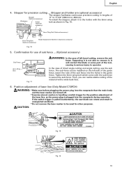
Supposing it is not able to remove it to the holder with the 6mm wing bolt as the power plug is pulled inadvertently, the saw blade can rotate and result in unexpected accidents. * Do not remove the laser marker to 450mm). In the case of direct angle ...body and the laser marker are optional accessory) The stopper facilitates continuous precision cutting in Fig. 10. 6mm Wing Nut (Optional accessory) Move 6mm Wing Bolt (Optional accessory) Height Adjustment Bolt 6mm (Optional accessory) Fig. 10 5. Tighten the 6mm wing bolt which come with a wide back face. 6. Position adjustment ...
Supposing it is not able to remove it to the holder with the 6mm wing bolt as the power plug is pulled inadvertently, the saw blade can rotate and result in unexpected accidents. * Do not remove the laser marker to 450mm). In the case of direct angle ...body and the laser marker are optional accessory) The stopper facilitates continuous precision cutting in Fig. 10. 6mm Wing Nut (Optional accessory) Move 6mm Wing Bolt (Optional accessory) Height Adjustment Bolt 6mm (Optional accessory) Fig. 10 5. Tighten the 6mm wing bolt which come with a wide back face. 6. Position adjustment ...

Operating Instructions
Page 14
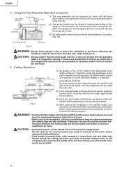
... can be lit up the laser marker and make a groove of the groove. 14 Workpiece Fig. 14 Saw Blade Marking (pre-marked) Cutting Width Fig. 15 (1) Light up . Laser Line Move Groove Fig....of the gear case, turn it ; Under such circumstances, move it with the right side of the saw blade, align the laser line with the left end of factory shipment. Switch Laser Line Ink lining can...-window operations, it may become difficult to observe the laser line due to the left side of the saw blade, align the laser line with the laser line. * When the ink line and the laser line...
... can be lit up the laser marker and make a groove of the groove. 14 Workpiece Fig. 14 Saw Blade Marking (pre-marked) Cutting Width Fig. 15 (1) Light up . Laser Line Move Groove Fig....of the gear case, turn it ; Under such circumstances, move it with the right side of the saw blade, align the laser line with the left end of factory shipment. Switch Laser Line Ink lining can...-window operations, it may become difficult to observe the laser line due to the left side of the saw blade, align the laser line with the laser line. * When the ink line and the laser line...
Operating Instructions
Page 16
... down gradually to cut into the workpiece. (4) After cutting the workpiece to the desired depth, turn the power tool OFF and let the saw blade stop completely before raising the handle from the receptacle whenever the tool is any cutoff thinner than the clearance between the cutting edge and... the saw blade may do so, loosen the 6 mm wing bolt (B) and move the vise assembly to the full retract position. otherwise the workpiece might ...
... down gradually to cut into the workpiece. (4) After cutting the workpiece to the desired depth, turn the power tool OFF and let the saw blade stop completely before raising the handle from the receptacle whenever the tool is any cutoff thinner than the clearance between the cutting edge and... the saw blade may do so, loosen the 6 mm wing bolt (B) and move the vise assembly to the full retract position. otherwise the workpiece might ...

Operating Instructions
Page 17
...of alignment, or with the right hand side for compound cutting. To prevent an accident or personal injury always firmly tighten the miter handle. 5. Indicator (for compound cutting, refer to the initial position. If the handle is raised while the saw blade is secured on the left side of the ..., the cut -off and let the saw blade might then contact the clamp or vise that the miter scale and the tip of the saw blade. Miter cutting procedures (1) Loosen the side handle and push the lever for compound cutting, because the saw blade stop completely before raising the handle from...
...of alignment, or with the right hand side for compound cutting. To prevent an accident or personal injury always firmly tighten the miter handle. 5. Indicator (for compound cutting, refer to the initial position. If the handle is raised while the saw blade is secured on the left side of the ..., the cut -off and let the saw blade might then contact the clamp or vise that the miter scale and the tip of the saw blade. Miter cutting procedures (1) Loosen the side handle and push the lever for compound cutting, because the saw blade stop completely before raising the handle from...

Operating Instructions
Page 19
...bolts to the fence; Position crown molding with the slope of crown molding without tilting the saw blade. Fence After adjusting the height, firmly tighten the 6mm wing bolt; Head Bevel Angle Scale 4 1 Fence Miter Angle Scale Turntable Fig. 26 Fence Base 2 Fence Fence Head Bevel Angle Scale 3 ...Base Turntable Miter Angle Scale Fig. 27 English Table on Base Table on either the left fence (Fence (B)) or the right fence 6mm Knob Bolt (Fence (A)). The main body or saw blade may do so, loosen the 6mm knob bolt and move...
...bolts to the fence; Position crown molding with the slope of crown molding without tilting the saw blade. Fence After adjusting the height, firmly tighten the 6mm wing bolt; Head Bevel Angle Scale 4 1 Fence Miter Angle Scale Turntable Fig. 26 Fence Base 2 Fence Fence Head Bevel Angle Scale 3 ...Base Turntable Miter Angle Scale Fig. 27 English Table on Base Table on either the left fence (Fence (B)) or the right fence 6mm Knob Bolt (Fence (A)). The main body or saw blade may do so, loosen the 6mm knob bolt and move...

Operating Instructions
Page 20
... When the dust bag has become full of sawdust, dust will be easily pressed in Fig. 33-c. When cutting aluminum materials, coat the saw blade rotates. This will accumulate more quickly than the 10mm box wrench (standard accessory), excessive or improperly tightening occurs, resulting in injury. 1. ...In addition, in case of the dust bag when the saw blade with 10mm box wrench (standard accessory) while applying pressure on the spindle lock. Duct Right Angle Base (2) During bevel and compound cutting, attach the dust bag at a right angle to achieve smooth cutting ...
... When the dust bag has become full of sawdust, dust will be easily pressed in Fig. 33-c. When cutting aluminum materials, coat the saw blade rotates. This will accumulate more quickly than the 10mm box wrench (standard accessory), excessive or improperly tightening occurs, resulting in injury. 1. ...In addition, in case of the dust bag when the saw blade with 10mm box wrench (standard accessory) while applying pressure on the spindle lock. Duct Right Angle Base (2) During bevel and compound cutting, attach the dust bag at a right angle to achieve smooth cutting ...

Operating Instructions
Page 21
...loose during operation. Dismounting the saw blade Dismount the saw blades larger than 10" (255mm) in paragraph 1 above. CAUTION: Never attempt to install saw blade by reversing the mounting procedures described in diameter. Always install saw blade. CAUTION: Never use a dull saw blades that the spindle lock ...always confirm that the rotation indicator mark on the saw blade and the rotation direction of the gear case (see Fig. 1) are 10" (255mm) in Fig. 33-c. A damaged saw blade can cause personal injury and a worn saw blade. Confirm the bolt has been properly tightened ...
...loose during operation. Dismounting the saw blade Dismount the saw blades larger than 10" (255mm) in paragraph 1 above. CAUTION: Never attempt to install saw blade by reversing the mounting procedures described in diameter. Always install saw blade. CAUTION: Never use a dull saw blades that the spindle lock ...always confirm that the rotation indicator mark on the saw blade and the rotation direction of the gear case (see Fig. 1) are 10" (255mm) in Fig. 33-c. A damaged saw blade can cause personal injury and a worn saw blade. Confirm the bolt has been properly tightened ...

Operating Instructions
Page 22
... properly and it is in Fig. 35. WARNING: To prevent personal injury, never operate the power tool if any loose part. After adjusting the saw blade with a slotted (minus) screwdriver. Inspecting the screws Regularly inspect each component of dust and the like . 5. Inspecting the carbon brushes (Fig... head bolts (2). Also, keep it moves smoothly. Re-tighten screws on any components are loose. 6. Never use of the fence and saw blade and fence to the wear limit line as shown in good condition and that they have become excessively worn, motor trouble might occur....
... properly and it is in Fig. 35. WARNING: To prevent personal injury, never operate the power tool if any loose part. After adjusting the saw blade with a slotted (minus) screwdriver. Inspecting the screws Regularly inspect each component of dust and the like . 5. Inspecting the carbon brushes (Fig... head bolts (2). Also, keep it moves smoothly. Re-tighten screws on any components are loose. 6. Never use of the fence and saw blade and fence to the wear limit line as shown in good condition and that they have become excessively worn, motor trouble might occur....

Parts List
Page 1
Hitachi Power Tools LIST NO. E946 ELECTRIC TOOL PARTS LIST COMPOUND SAW Model C 10FCE2 2006 • 10 • 11 (E1) 4 5 6 7 13 14 46 47 48 49 50 3 9 8 12 11 10 22 23 24 25 26 21 15 16 39 40 41 42 43 44 45 18 19 20 38 27 28 29 53 54 55 56 57 51 52 58 602 603 604 601 605 606 30 607 31 608 32 33 34 35 36 37 628 601 609 59 63 60 64 61 62 614 615 616 618 617 46 47 48 65 629 615 619 626 627 619 620 613 609 612 611 610 621 622 623 67 626 624 627 66 625
Hitachi Power Tools LIST NO. E946 ELECTRIC TOOL PARTS LIST COMPOUND SAW Model C 10FCE2 2006 • 10 • 11 (E1) 4 5 6 7 13 14 46 47 48 49 50 3 9 8 12 11 10 22 23 24 25 26 21 15 16 39 40 41 42 43 44 45 18 19 20 38 27 28 29 53 54 55 56 57 51 52 58 602 603 604 601 605 606 30 607 31 608 32 33 34 35 36 37 628 601 609 59 63 60 64 61 62 614 615 616 618 617 46 47 48 65 629 615 619 626 627 619 620 613 609 612 611 610 621 622 623 67 626 624 627 66 625

Parts List
Page 4
... TCT SAW BLADE 255MM-D25.4 HOLE-NT100 1 * 103 974-663Z COLLAR (A) FOR D30 HOLE 1 FOR EUROPE * 103 976-819 COLLAR (B) FOR D25.4 HOLE 1 FOR AUS, INA, MAL, SIN, SYR, THA, CHN 104 323-133 SPINDLE ASS'Y 1 INCLUD. 105-109 105 990-430 SEAL LOCK FLAT HD. SOCKET HD. SCREW M6X16 (10 PCS....) 1 118 949-217 MACHINE SCREW M4X12 (10 PCS.) 1 119 949-429 BOLT WASHER M4 (10 PCS.) 1 120 322-920 HOOK 1 121 326-708 HANDLE 1 122 323-208 MACHINE SCREW (W/WASHERS) M6X20 (BLACK) 2 * 123...
... TCT SAW BLADE 255MM-D25.4 HOLE-NT100 1 * 103 974-663Z COLLAR (A) FOR D30 HOLE 1 FOR EUROPE * 103 976-819 COLLAR (B) FOR D25.4 HOLE 1 FOR AUS, INA, MAL, SIN, SYR, THA, CHN 104 323-133 SPINDLE ASS'Y 1 INCLUD. 105-109 105 990-430 SEAL LOCK FLAT HD. SOCKET HD. SCREW M6X16 (10 PCS....) 1 118 949-217 MACHINE SCREW M4X12 (10 PCS.) 1 119 949-429 BOLT WASHER M4 (10 PCS.) 1 120 322-920 HOOK 1 121 326-708 HANDLE 1 122 323-208 MACHINE SCREW (W/WASHERS) M6X20 (BLACK) 2 * 123...

Parts List
Page 7
...BOLT M6X80 1 626 974-561 STOPPER 1 627 949-404 WING BOLT M6X20 (10 PCS.) 1 628 322-712 CROWN MOLDING VISE ASS'Y 1 INCLUD. 601, 609 629 322-710 GUIDE ASS'Y 1 INCLUD. 615, 619, 626, 627 * 630 976-472 TCT SAW BLADE CROSS-CUT 255MM-D15.9 HOLE 1 FOR USA, CAN * 631 319...-658 TCT SAW BLADE 255MM-D15.88 HOLE-NT100 1 FOR USA, CAN C 10FCE2 10 -- 06 * ALTERNATIVE PARTS --- 7 --- STANDARD ACCESSORIES ITEM NO. DESCRIPTION NO. USED 1 1 1 FOR ...
...BOLT M6X80 1 626 974-561 STOPPER 1 627 949-404 WING BOLT M6X20 (10 PCS.) 1 628 322-712 CROWN MOLDING VISE ASS'Y 1 INCLUD. 601, 609 629 322-710 GUIDE ASS'Y 1 INCLUD. 615, 619, 626, 627 * 630 976-472 TCT SAW BLADE CROSS-CUT 255MM-D15.9 HOLE 1 FOR USA, CAN * 631 319...-658 TCT SAW BLADE 255MM-D15.88 HOLE-NT100 1 FOR USA, CAN C 10FCE2 10 -- 06 * ALTERNATIVE PARTS --- 7 --- STANDARD ACCESSORIES ITEM NO. DESCRIPTION NO. USED 1 1 1 FOR ...


