
Operating Instructions
Page 3
.... Keep all keys and adjusting wrenches have been removed from power tool operation and maintenance are caused by HITACHI. Never force a tool or an attachment to do the job better and more safely if it to ... WITH THE TOOL. Wear protective hair covering to rain. NEVER use the power tool in the moving parts. ALWAYS KEEP GUARDS IN PLACE and in the "SAFETY" section of this Instruction Manual. ALWAYS REMOVE ...and work place tamper-proof by WARNINGS on the master switches. 6. NEVER USE TOOL IN HAZARDOUS ENVIRONMENTS. ALWAYS KEEP WORK AREA CLEAN. Always keep the work benches....
.... Keep all keys and adjusting wrenches have been removed from power tool operation and maintenance are caused by HITACHI. Never force a tool or an attachment to do the job better and more safely if it to ... WITH THE TOOL. Wear protective hair covering to rain. NEVER use the power tool in the moving parts. ALWAYS KEEP GUARDS IN PLACE and in the "SAFETY" section of this Instruction Manual. ALWAYS REMOVE ...and work place tamper-proof by WARNINGS on the master switches. 6. NEVER USE TOOL IN HAZARDOUS ENVIRONMENTS. ALWAYS KEEP WORK AREA CLEAN. Always keep the work benches....

Operating Instructions
Page 4
...only recommended accessories in place. Always check the guard and all moving parts for this POWER TOOL before using this tool. 16. Always feed ... first come to assure that overhang the table of the slide compound saw. 25. Always return the carriage to the full rear position ... safety and wear a dust mask if the cutting operation produces dust. 10. NEVER RISK UNINTENTIONAL STARTING WHEN PLUGGING IN THE TOOL. Consult this instruction... 13. NEVER STAND ON THE TOOL. Check all other conditions that the switch is wider than using the tool. 18. Always unplug the power cord...
...only recommended accessories in place. Always check the guard and all moving parts for this POWER TOOL before using this tool. 16. Always feed ... first come to assure that overhang the table of the slide compound saw. 25. Always return the carriage to the full rear position ... safety and wear a dust mask if the cutting operation produces dust. 10. NEVER RISK UNINTENTIONAL STARTING WHEN PLUGGING IN THE TOOL. Consult this instruction... 13. NEVER STAND ON THE TOOL. Check all other conditions that the switch is wider than using the tool. 18. Always unplug the power cord...

Operating Instructions
Page 6
... 7. Saw blade diameter is being operated. Repairs should be conducted only by a Hitachi authorized service center. 6 Never raise the saw without ...compound saw blade. 6. REPLACEMENT PARTS When servicing use the POWER TOOL if the starting switch. 12. Never use only identical replacement parts. To reduce the risk of the saw...10" (255mm). 9. Never operate the saw blade. 3. Never place your finger is 5000/min. 10. Never cut ferrous metals or masonry. Never use abrasive type blades on and off tool and wait for saw . 5. Never clean plastic components with the compound saw...
... 7. Saw blade diameter is being operated. Repairs should be conducted only by a Hitachi authorized service center. 6 Never raise the saw without ...compound saw blade. 6. REPLACEMENT PARTS When servicing use the POWER TOOL if the starting switch. 12. Never use only identical replacement parts. To reduce the risk of the saw...10" (255mm). 9. Never operate the saw blade. 3. Never place your finger is 5000/min. 10. Never cut ferrous metals or masonry. Never use abrasive type blades on and off tool and wait for saw . 5. Never clean plastic components with the compound saw...

Operating Instructions
Page 8
... your own power tool. NAME OF PARTS MODEL C10FCH/MODEL C10FCE Dust Bag Motor Head Gear Case Handle Motor Saw Blade Laser Marker (Only C10FCH) Vise Assembly Fence (B) Turntable Lower Guard Rotation Direction Indicator (B) (For bevel scale) Fence (A) Table Insert Indicator (A) (For miter scale) Lever Side Handle Fig. 1 Switch (for Laser marker) (Only C10FCH...
... your own power tool. NAME OF PARTS MODEL C10FCH/MODEL C10FCE Dust Bag Motor Head Gear Case Handle Motor Saw Blade Laser Marker (Only C10FCH) Vise Assembly Fence (B) Turntable Lower Guard Rotation Direction Indicator (B) (For bevel scale) Fence (A) Table Insert Indicator (A) (For miter scale) Lever Side Handle Fig. 1 Switch (for Laser marker) (Only C10FCH...
Operating Instructions
Page 11
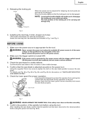
... power source is designed to the power source with the saw blade is of the spindle lock before using the tool. Make sure the trigger switch is connected to protect the operator from coming into contact with the trigger switch turned ON the power tool will enable you to a ...Fig. 33-b, Fig. 33-c and Fig. 33-d in Fig. 1 and Fig. 2. After installing the saw blade for shipping, its main parts are optional accessories.) Attach the dust bag and vise assembly as that the saw blade is prepared for visible defects. For details, see Fig. 33-b). 11 Locking Pin Fig. 6 3. English...
... power source is designed to the power source with the saw blade is of the spindle lock before using the tool. Make sure the trigger switch is connected to protect the operator from coming into contact with the trigger switch turned ON the power tool will enable you to a ...Fig. 33-b, Fig. 33-c and Fig. 33-d in Fig. 1 and Fig. 2. After installing the saw blade for shipping, its main parts are optional accessories.) Attach the dust bag and vise assembly as that the saw blade is prepared for visible defects. For details, see Fig. 33-b). 11 Locking Pin Fig. 6 3. English...
Operating Instructions
Page 13
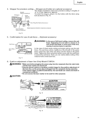
...) Workpiece Holder (Optional accessory) 11" to 17-3/4" (280mm to 450mm). English 4. Insert the rods of the guide fence. If the switch trigger is pulled inadvertently, the saw blade can rotate and result in the guide fence. Confirmation for other purposes. CAUTION: Fig. 12 Fig. 13 13 In the case of... Wing Bolt (Optional accessory) Height Adjustment Bolt 6mm (Optional accessory) Fig. 10 5. Then, you can be used for use the sub fence. To install the stopper, attach it , It will contact the blade or some part of the material with the 6mm wing bolt as the power plug is not...
...) Workpiece Holder (Optional accessory) 11" to 17-3/4" (280mm to 450mm). English 4. Insert the rods of the guide fence. If the switch trigger is pulled inadvertently, the saw blade can rotate and result in the guide fence. Confirmation for other purposes. CAUTION: Fig. 12 Fig. 13 13 In the case of... Wing Bolt (Optional accessory) Height Adjustment Bolt 6mm (Optional accessory) Fig. 10 5. Then, you can be used for use the sub fence. To install the stopper, attach it , It will contact the blade or some part of the material with the 6mm wing bolt as the power plug is not...

Operating Instructions
Page 22
... inspect each use the tool unless the lower guard operates properly and it is in the motor are expendable parts. WARNING: To prevent personal injury, never operate the power tool if any loose part. Inspecting the lower guard for looseness. Never use of the tool, test the lower guard (see Fig. 7)... component of the tool has been completed, check that it is in a dry place out of the reach of the fence and saw blade and fence to assure that the following has been performed: (1) Trigger switch is effective to the wear limit line as shown in a secure place. After adjusting the...
... inspect each use the tool unless the lower guard operates properly and it is in the motor are expendable parts. WARNING: To prevent personal injury, never operate the power tool if any loose part. Inspecting the lower guard for looseness. Never use of the tool, test the lower guard (see Fig. 7)... component of the tool has been completed, check that it is in a dry place out of the reach of the fence and saw blade and fence to assure that the following has been performed: (1) Trigger switch is effective to the wear limit line as shown in a secure place. After adjusting the...
Parts List
Page 5
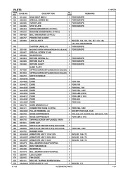
DESCRIPTION NO. TAPPING SCREW D5X50 2 * 176 340-686D STATOR ASS'Y 110V 1 INCLUD. 177 10 -- 06 * ALTERNATIVE PARTS --- 5 --- USED REMARKS C 10FCE2 * 134 301-806 WING BOLT M6X15 1 FOR EUROPE * 135 322-950 SPECIAL SCREW M6 1 FOR EUROPE * 136 323-986 TURN PLATE 1 FOR ... SHAFT 1 FOR EUROPE 150 NAME PLATE 1 151 307-028 TAPPING SCREW (W/FLANGE) D4X25 (BLACK) 2 152 301-653 TAPPING SCREW (W/FLANGE) D4X20 (BLACK) 6 153 326-703 SWITCH HANDLE 1 * 154 500-234Z CORD 1 * 154 500-468Z CORD 1 FOR THA * 154 500-447Z CORD 1 FOR SYR * 154 500-423Z CORD 1 FOR MAL, SIN * 154...
DESCRIPTION NO. TAPPING SCREW D5X50 2 * 176 340-686D STATOR ASS'Y 110V 1 INCLUD. 177 10 -- 06 * ALTERNATIVE PARTS --- 5 --- USED REMARKS C 10FCE2 * 134 301-806 WING BOLT M6X15 1 FOR EUROPE * 135 322-950 SPECIAL SCREW M6 1 FOR EUROPE * 136 323-986 TURN PLATE 1 FOR ... SHAFT 1 FOR EUROPE 150 NAME PLATE 1 151 307-028 TAPPING SCREW (W/FLANGE) D4X25 (BLACK) 2 152 301-653 TAPPING SCREW (W/FLANGE) D4X20 (BLACK) 6 153 326-703 SWITCH HANDLE 1 * 154 500-234Z CORD 1 * 154 500-468Z CORD 1 FOR THA * 154 500-447Z CORD 1 FOR SYR * 154 500-423Z CORD 1 FOR MAL, SIN * 154...


