
Operating Instructions
Page 3
..." section of electric shock or other jewelry which , if not avoided, may result in minor or moderate injury, or may get caught in the moving parts. CAUTION indicates a potentially hazardous situations which may cause machine damage. Always confirm that must be avoided by WARNINGS on the master switches. 6. Keep all people.... ALWAYS WEAR PROPER APPAREL WHEN WORKING WITH THE TOOL. An accident can often be avoided to prevent bodily injury or machine damage are caused by HITACHI. Most accidents that has not been specifically recommended by the failure to contain long hair. 3
..." section of electric shock or other jewelry which , if not avoided, may result in minor or moderate injury, or may get caught in the moving parts. CAUTION indicates a potentially hazardous situations which may cause machine damage. Always confirm that must be avoided by WARNINGS on the master switches. 6. Keep all people.... ALWAYS WEAR PROPER APPAREL WHEN WORKING WITH THE TOOL. An accident can often be avoided to prevent bodily injury or machine damage are caused by HITACHI. Most accidents that has not been specifically recommended by the failure to contain long hair. 3

Operating Instructions
Page 4
...TOOL. To avoid personal injuries, use only recommended accessories in use. ALWAYS CHECK FOR DAMAGED PARTS BEFORE USING THE TOOL. Check all other accessories. 14. Always repair or replace any way...Ordinary eyeglasses do not provide adequate protection because the lenses are not made of the slide compound saw blade. 17. Always follow instructions for lubricating the tool and for descriptions of electric ... for additional safety and wear a dust mask if the cutting operation produces dust. 10. Also, use a face mask for damage before attempting to assure that the switch is...
...TOOL. To avoid personal injuries, use only recommended accessories in use. ALWAYS CHECK FOR DAMAGED PARTS BEFORE USING THE TOOL. Check all other accessories. 14. Always repair or replace any way...Ordinary eyeglasses do not provide adequate protection because the lenses are not made of the slide compound saw blade. 17. Always follow instructions for lubricating the tool and for descriptions of electric ... for additional safety and wear a dust mask if the cutting operation produces dust. 10. Also, use a face mask for damage before attempting to assure that the switch is...

Operating Instructions
Page 5
...trial run first before using the tool. 10. Never leave the POWER TOOL unattended without them would be thrust form the table and cause bodily harm. 10. Never use of the tool without first... a hard object, it . 3. Never touch any new use on the supporting surface. During miter or bevel cutting, always wait for use of the tool. 5 Always confirm that the motor ... support for applications not specified in the moving parts, including the blade, while the saw . 22. Always confirm that the proper lengths and types of the compound saw is free of the blade to tip over...
...trial run first before using the tool. 10. Never leave the POWER TOOL unattended without them would be thrust form the table and cause bodily harm. 10. Never use of the tool without first... a hard object, it . 3. Never touch any new use on the supporting surface. During miter or bevel cutting, always wait for use of the tool. 5 Always confirm that the motor ... support for applications not specified in the moving parts, including the blade, while the saw . 22. Always confirm that the proper lengths and types of the compound saw is free of the blade to tip over...

Operating Instructions
Page 6
...away from the workpiece. Always wear eye protection when using the compound saw without the guards in place. 17. Never reach around the saw blade. 3. To reduce the risk of the saw blade. 6. REPLACEMENT PARTS When servicing use the POWER TOOL near flammable liquids or gases ...pull the handle toward the operator, since this saw blade to warning sign " " while the tool is 10" (255mm). 9. WARNING FOR YOUR OWN SAFETY READ THIS INSTRUCTION MANUAL BEFORE OPERATING THE COMPOUND SAW 1. Repairs should be conducted only by a Hitachi authorized service center. 6 Never place your ...
...away from the workpiece. Always wear eye protection when using the compound saw without the guards in place. 17. Never reach around the saw blade. 3. To reduce the risk of the saw blade. 6. REPLACEMENT PARTS When servicing use the POWER TOOL near flammable liquids or gases ...pull the handle toward the operator, since this saw blade to warning sign " " while the tool is 10" (255mm). 9. WARNING FOR YOUR OWN SAFETY READ THIS INSTRUCTION MANUAL BEFORE OPERATING THE COMPOUND SAW 1. Repairs should be conducted only by a Hitachi authorized service center. 6 Never place your ...
Operating Instructions
Page 7
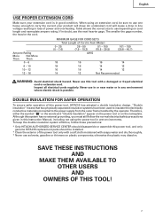
Never use this power tool, and only genuine HITACHI replacement parts should disassemble or assemble this tool with soapy water and dry... TO OTHER USERS AND OWNERS OF THIS TOOL! 7 Ampere Rating More Not More Than Than 0 - 6 6 - 10 10 - 12 12 - 16 MINIMUM GAGE FOR CORD SETS Total Length of Cord in loss of power and overheating. Never... regularly. Although this system has no external grounding, you must still follow these precautions: * Only HITACHI AUTHORIZED SERVICE CENTER should be sure to use depending on cord length and nameplate ampere rating. DOUBLE INSULATION...
Never use this power tool, and only genuine HITACHI replacement parts should disassemble or assemble this tool with soapy water and dry... TO OTHER USERS AND OWNERS OF THIS TOOL! 7 Ampere Rating More Not More Than Than 0 - 6 6 - 10 10 - 12 12 - 16 MINIMUM GAGE FOR CORD SETS Total Length of Cord in loss of power and overheating. Never... regularly. Although this system has no external grounding, you must still follow these precautions: * Only HITACHI AUTHORIZED SERVICE CENTER should be sure to use depending on cord length and nameplate ampere rating. DOUBLE INSULATION...

Operating Instructions
Page 8
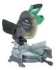
... NOTE: The information contained in the safe operation and maintenance of the power tool. NAME OF PARTS MODEL C10FCH/MODEL C10FCE Dust Bag Motor Head Gear Case Handle Motor Saw Blade Laser Marker (Only C10FCH) Vise Assembly Fence (B) Turntable Lower Guard Rotation Direction Indicator (B)... (For bevel scale) Fence (A) Table Insert Indicator (A) (For miter scale) Lever Side Handle Fig. 1 Switch (for Laser ...
... NOTE: The information contained in the safe operation and maintenance of the power tool. NAME OF PARTS MODEL C10FCH/MODEL C10FCE Dust Bag Motor Head Gear Case Handle Motor Saw Blade Laser Marker (Only C10FCH) Vise Assembly Fence (B) Turntable Lower Guard Rotation Direction Indicator (B)... (For bevel scale) Fence (A) Table Insert Indicator (A) (For miter scale) Lever Side Handle Fig. 1 Switch (for Laser ...
Operating Instructions
Page 11
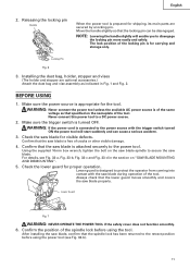
...supplied 10mm box wrench, tighten the bolt on "SAW BLADE MOUNTING AND DISMOUNTING". 5. For details, see Fig. 33-b). 11 Confirm the position of cracks or other visible damage. 4. Make sure the power source is for shipping, its main parts are optional accessories.) Attach the dust bag and ... contact with the trigger switch turned ON the power tool will enable you to secure the saw blade for proper operation. Check the lower guard for visible defects. Check the saw blade. English 2. Always check that the spindle lock has been returned to the retract position...
...supplied 10mm box wrench, tighten the bolt on "SAW BLADE MOUNTING AND DISMOUNTING". 5. For details, see Fig. 33-b). 11 Confirm the position of cracks or other visible damage. 4. Make sure the power source is for shipping, its main parts are optional accessories.) Attach the dust bag and ... contact with the trigger switch turned ON the power tool will enable you to secure the saw blade for proper operation. Check the lower guard for visible defects. Check the saw blade. English 2. Always check that the spindle lock has been returned to the retract position...
Operating Instructions
Page 13
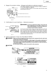
...turned off. * Exercise utmost caution in Fig. 10. 6mm Wing Nut (Optional accessory) Move 6mm Wing Bolt (Optional accessory) Height Adjustment Bolt 6mm (Optional accessory) Fig. 10 5. Insert the rods of the sub fence into.... 12 Fig. 13 13 To install the stopper, attach it , It will contact the blade or some part of laser line (Only Model C10FCH) WARNING: * Make sure before plugging the power plug into the receptacle... which come with the 6mm wing bolt as the power plug is pulled inadvertently, the saw blade can rotate and result in serious injury to secure the sub fence. The sub ...
...turned off. * Exercise utmost caution in Fig. 10. 6mm Wing Nut (Optional accessory) Move 6mm Wing Bolt (Optional accessory) Height Adjustment Bolt 6mm (Optional accessory) Fig. 10 5. Insert the rods of the sub fence into.... 12 Fig. 13 13 To install the stopper, attach it , It will contact the blade or some part of laser line (Only Model C10FCH) WARNING: * Make sure before plugging the power plug into the receptacle... which come with the 6mm wing bolt as the power plug is pulled inadvertently, the saw blade can rotate and result in serious injury to secure the sub fence. The sub ...

Operating Instructions
Page 22
...(2) Power plug has been removed from a wind hole at the motor's rear. Inspecting the lever If the M6 hexagonal head bolts (2) are expendable parts. Head Bolt Steel Square Fig. 34-a Fig. 34-b 3. Inspecting the carbon brushes (Fig. 35 and Fig. 36) The carbon brushes in... the following has been performed: (1) Trigger switch is in a malfunction. English 2. After using the motor for looseness. After adjusting the saw blade with a slotted (minus) screwdriver. Therefore, inspect the carbon brushes periodically and replace them when they will slide smoothly within the brush...
...(2) Power plug has been removed from a wind hole at the motor's rear. Inspecting the lever If the M6 hexagonal head bolts (2) are expendable parts. Head Bolt Steel Square Fig. 34-a Fig. 34-b 3. Inspecting the carbon brushes (Fig. 35 and Fig. 36) The carbon brushes in... the following has been performed: (1) Trigger switch is in a malfunction. English 2. After using the motor for looseness. After adjusting the saw blade with a slotted (minus) screwdriver. Therefore, inspect the carbon brushes periodically and replace them when they will slide smoothly within the brush...

Operating Instructions
Page 23
... be used and that the double insulation system will eventually require servicing or replacement of parts because of wear from contact with oil or water. (Only Model C10FCH) If the laser line becomes invisible due to chips and the like adhered .... SERVICE AND REPAIRS All quality power tools will be performed by an AUTHORIZED HITACHI POWER TOOL REPAIR CENTER ONLY. To avoid a malfunction of HITACHI. 23 Lubrication Lubricate the following sliding surfaces once a month to change without any obligation on the part of the motor, protect it from normal use. NOTE: Specifications are subject...
... be used and that the double insulation system will eventually require servicing or replacement of parts because of wear from contact with oil or water. (Only Model C10FCH) If the laser line becomes invisible due to chips and the like adhered .... SERVICE AND REPAIRS All quality power tools will be performed by an AUTHORIZED HITACHI POWER TOOL REPAIR CENTER ONLY. To avoid a malfunction of HITACHI. 23 Lubrication Lubricate the following sliding surfaces once a month to change without any obligation on the part of the motor, protect it from normal use. NOTE: Specifications are subject...

Parts List
Page 1
E946 ELECTRIC TOOL PARTS LIST COMPOUND SAW Model C 10FCE2 2006 • 10 • 11 (E1) 4 5 6 7 13 14 46 47 48 49 50 3 9 8 12 11 10 22 23 24 25 26 21 15 16 39 40 41 42 43 44 45 18 19 20 38 27 28 29 53 54 55 56 57 51 52 58 602 603 604 601 605 606 30 607 31 608 32 33 34 35 36 37 628 601 609 59 63 60 64 61 62 614 615 616 618 617 46 47 48 65 629 615 619 626 627 619 620 613 609 612 611 610 621 622 623 67 626 624 627 66 625 Hitachi Power Tools LIST NO.
E946 ELECTRIC TOOL PARTS LIST COMPOUND SAW Model C 10FCE2 2006 • 10 • 11 (E1) 4 5 6 7 13 14 46 47 48 49 50 3 9 8 12 11 10 22 23 24 25 26 21 15 16 39 40 41 42 43 44 45 18 19 20 38 27 28 29 53 54 55 56 57 51 52 58 602 603 604 601 605 606 30 607 31 608 32 33 34 35 36 37 628 601 609 59 63 60 64 61 62 614 615 616 618 617 46 47 48 65 629 615 619 626 627 619 620 613 609 612 611 610 621 622 623 67 626 624 627 66 625 Hitachi Power Tools LIST NO.

Parts List
Page 3
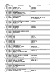
CODE NO. 3 307-956 DESCRIPTION NO. SCREW M6X25 (10 PCS.) 1 53 326-704 SUB FENCE (B) 1 54 326-698 FENCE (B) 1 10 -- 06 * ALTERNATIVE PARTS C 10FCE2 --- 3 --- USED SEAL LOCK HEX. SOCKET SET SCREW M6X10 1 REMARKS 4 323-208 MACHINE SCREW (W/WASHERS) M6X20 (BLACK) 1 5 322-935 CLAMP LEVER 1 6 326-706 BOLT (LEFT ...
CODE NO. 3 307-956 DESCRIPTION NO. SCREW M6X25 (10 PCS.) 1 53 326-704 SUB FENCE (B) 1 54 326-698 FENCE (B) 1 10 -- 06 * ALTERNATIVE PARTS C 10FCE2 --- 3 --- USED SEAL LOCK HEX. SOCKET SET SCREW M6X10 1 REMARKS 4 323-208 MACHINE SCREW (W/WASHERS) M6X20 (BLACK) 1 5 322-935 CLAMP LEVER 1 6 326-706 BOLT (LEFT ...

Parts List
Page 4
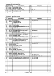
....) 2 FOR EUROPE, USA, CAN, AUS, MAL 132 322-950 SPECIAL SCREW M6 1 133 322-948 WASHER M7 2 --- 4 --- * ALTERNATIVE PARTS 10 -- 06 WASHER) M5X16 2 115 949-819 HEX. BOLT M8X16 (10 PCS.) 2 62 326-826 SCALE (A) 1 63 326-696 SPACER (A) 1 64 317-200 MACHINE SCREW (W/WASHERS) M4X8 (BLACK) 1 65 326-697 ...-962 WASHER (B) 1 FOR EUROPE, CHN * 102 319-107 TCT SAW BLADE 255MM-D30 HOLE-NT30 1 * 102 319-106 TCT SAW BLADE 255MM-D25.4 HOLE-NT24 1 * 102 318-963 TCT SAW BLADE 255MM-D15.88 HOLE-NT24 1 * 102 318-964 TCT SAW BLADE 255MM-D25.4 HOLE-NT100 1 * 103 974-663Z COLLAR (A) ...
....) 2 FOR EUROPE, USA, CAN, AUS, MAL 132 322-950 SPECIAL SCREW M6 1 133 322-948 WASHER M7 2 --- 4 --- * ALTERNATIVE PARTS 10 -- 06 WASHER) M5X16 2 115 949-819 HEX. BOLT M8X16 (10 PCS.) 2 62 326-826 SCALE (A) 1 63 326-696 SPACER (A) 1 64 317-200 MACHINE SCREW (W/WASHERS) M4X8 (BLACK) 1 65 326-697 ...-962 WASHER (B) 1 FOR EUROPE, CHN * 102 319-107 TCT SAW BLADE 255MM-D30 HOLE-NT30 1 * 102 319-106 TCT SAW BLADE 255MM-D25.4 HOLE-NT24 1 * 102 318-963 TCT SAW BLADE 255MM-D15.88 HOLE-NT24 1 * 102 318-964 TCT SAW BLADE 255MM-D25.4 HOLE-NT100 1 * 103 974-663Z COLLAR (A) ...
Parts List
Page 5
CODE NO. HD. TAPPING SCREW D5X50 2 * 176 340-686D STATOR ASS'Y 110V 1 INCLUD. 177 10 -- 06 * ALTERNATIVE PARTS --- 5 --- USED REMARKS C 10FCE2 * 134 301-806 WING BOLT M6X15 1 FOR EUROPE * 135 322-950 SPECIAL SCREW M6 1 FOR EUROPE * 136 323-986 TURN PLATE 1 ...FOR EUROPE * 137 323-985 STOP PLATE 1 FOR EUROPE 138 949-454 SPRING WASHER M5 (10 PCS.) 1 139 949-215 MACHINE SCREW M4X8 (10 PCS.) 3 ...
CODE NO. HD. TAPPING SCREW D5X50 2 * 176 340-686D STATOR ASS'Y 110V 1 INCLUD. 177 10 -- 06 * ALTERNATIVE PARTS --- 5 --- USED REMARKS C 10FCE2 * 134 301-806 WING BOLT M6X15 1 FOR EUROPE * 135 322-950 SPECIAL SCREW M6 1 FOR EUROPE * 136 323-986 TURN PLATE 1 ...FOR EUROPE * 137 323-985 STOP PLATE 1 FOR EUROPE 138 949-454 SPRING WASHER M5 (10 PCS.) 1 139 949-215 MACHINE SCREW M4X8 (10 PCS.) 3 ...

Parts List
Page 6
... (1 PAIR) 2 FOR 110V-120V * 182 999-065 CARBON BRUSH (1 PAIR) 2 FOR 220V-240V 183 945-161 BRUSH CAP 2 * 184 322-949 LINK 1 C 10FCE2 --- 6 --- * ALTERNATIVE PARTS 10 -- 06 PARTS ITEM NO. CODE NO. USED REMARKS 1 INCLUD. 177 * 176 340-687E STATOR ASS'Y (B) 220V-230V 1 INCLUD. 177 * 176 340-686E STATOR ASS'Y 220V 1 INCLUD. 177...
... (1 PAIR) 2 FOR 110V-120V * 182 999-065 CARBON BRUSH (1 PAIR) 2 FOR 220V-240V 183 945-161 BRUSH CAP 2 * 184 322-949 LINK 1 C 10FCE2 --- 6 --- * ALTERNATIVE PARTS 10 -- 06 PARTS ITEM NO. CODE NO. USED REMARKS 1 INCLUD. 177 * 176 340-687E STATOR ASS'Y (B) 220V-230V 1 INCLUD. 177 * 176 340-686E STATOR ASS'Y 220V 1 INCLUD. 177...
Parts List
Page 7
... M6X80 1 626 974-561 STOPPER 1 627 949-404 WING BOLT M6X20 (10 PCS.) 1 628 322-712 CROWN MOLDING VISE ASS'Y 1 INCLUD. 601, 609 629 322-710 GUIDE ASS'Y 1 INCLUD. 615, 619, 626, 627 * 630 976-472 TCT SAW BLADE CROSS-CUT 255MM-D15.9 HOLE 1 FOR USA, CAN * 631 319...-658 TCT SAW BLADE 255MM-D15.88 HOLE-NT100 1 FOR USA, CAN C 10FCE2 10 -- 06 * ALTERNATIVE PARTS --- 7 --- DESCRIPTION NO. STANDARD ACCESSORIES ITEM NO.
... M6X80 1 626 974-561 STOPPER 1 627 949-404 WING BOLT M6X20 (10 PCS.) 1 628 322-712 CROWN MOLDING VISE ASS'Y 1 INCLUD. 601, 609 629 322-710 GUIDE ASS'Y 1 INCLUD. 615, 619, 626, 627 * 630 976-472 TCT SAW BLADE CROSS-CUT 255MM-D15.9 HOLE 1 FOR USA, CAN * 631 319...-658 TCT SAW BLADE 255MM-D15.88 HOLE-NT100 1 FOR USA, CAN C 10FCE2 10 -- 06 * ALTERNATIVE PARTS --- 7 --- DESCRIPTION NO. STANDARD ACCESSORIES ITEM NO.


