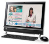
HP TouchSmart 9100 Stand - Business PC
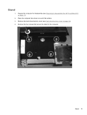
HP TouchSmart 9100 Stand
View Results Below
Free HP TouchSmart 9100 manuals!
Problems with HP TouchSmart 9100?
Ask a Question
Free HP TouchSmart 9100 manuals!
Problems with HP TouchSmart 9100?
Ask a Question
Related Manual Pages


Similar Questions

Putting Stand Back On An Iq500
I need to put the stand back on my IQ 500 and can't find a video or any instructions on how to do th...
I need to put the stand back on my IQ 500 and can't find a video or any instructions on how to do th...
(Posted by sissy6224 8 years ago)

How To Put Stand Of Hp Touchsmart Down
(Posted by qsralp 9 years ago)
What Base Stand Will Fit This Computer
oem stand for this computer is dicontinued and i need a stand
oem stand for this computer is dicontinued and i need a stand
(Posted by shanembailey 10 years ago)
Related Terms
The following terms were also used when searching for HP TouchSmart 9100 Stand - Business PC:- hp touchsmart 9100
- touchsmart 9100
- hp touchsmart 9100 business
- hp touchsmart 9100 business pc
- touchsmart 9100 business
- touchsmart 9100 business pc
- touchsmart 9100 t6570
- hp touchsmart 9100 price
- touchsmart 9100 pc
- touchsmart 9100 price
- buy hp touchsmart 9100
- hp touchsmart 9100 desktop
- hp touchsmart 9100 pc
- touchsmart 9100 aio
- touchsmart 9100 review
- hp touchsmart 9100 specs
- touchsmart 9100 bus pc
- touchsmart 9100 drivers
- touchsmart 9100 dual monitor
- touchsmart 9100 resolution
- touchsmart 9100 wall mount
- buy touchsmart 9100
- hp touchsmart 9100 23
- hp touchsmart 9100 23 inch
- hp touchsmart 9100 adapter
- hp touchsmart 9100 adjust brightness
- hp touchsmart 9100 aio
- hp touchsmart 9100 all in one pc
- hp touchsmart 9100 all-in-one pc
- hp touchsmart 9100 all-in-one pc windows 8
- hp touchsmart 9100 backlight problems
- hp touchsmart 9100 bios
- hp touchsmart 9100 bios update
- hp touchsmart 9100 black screen
- hp touchsmart 9100 brightness
- hp touchsmart 9100 bus pc
- hp touchsmart 9100 business all-in-one computer
- hp touchsmart 9100 business all-in-one pc
- hp touchsmart 9100 business pc graphics
- hp touchsmart 9100 calibration
- hp touchsmart 9100 computer
- hp touchsmart 9100 core 2 duo
- hp touchsmart 9100 cost
- hp touchsmart 9100 cpu fan
- hp touchsmart 9100 cpu upgrade
- hp touchsmart 9100 desktop computer
- hp touchsmart 9100 dimensions
- hp touchsmart 9100 disassembly
- hp touchsmart 9100 driver
- hp touchsmart 9100 driver touch screen
- hp touchsmart 9100 drivers
- hp touchsmart 9100 drivers for windows 8
- hp touchsmart 9100 dual monitor
- hp touchsmart 9100 dvd drive not working
- hp touchsmart 9100 dvd not working
- hp touchsmart 9100 elite all-in-one pc
- hp touchsmart 9100 ethernet port
- hp touchsmart 9100 for sale
- hp touchsmart 9100 hard drive removal
- hp touchsmart 9100 i/o cover
- hp touchsmart 9100 i/o cover part number
- hp touchsmart 9100 i/o cover part replacement
- hp touchsmart 9100 linux
- hp touchsmart 9100 manual
- hp touchsmart 9100 memory
- hp touchsmart 9100 memory replacement
- hp touchsmart 9100 memory upgrade
- hp touchsmart 9100 monitor
- hp touchsmart 9100 motherboard
- hp touchsmart 9100 mount
- hp touchsmart 9100 no video
- hp touchsmart 9100 parts
- hp touchsmart 9100 philippines
- hp touchsmart 9100 power
- hp touchsmart 9100 power adapter
- hp touchsmart 9100 power cord
- hp touchsmart 9100 power supply
- hp touchsmart 9100 ram
- hp touchsmart 9100 ram upgrade
- hp touchsmart 9100 reboot disk
- hp touchsmart 9100 recovery cd
- hp touchsmart 9100 recovery disc
- hp touchsmart 9100 replace hard drive
- hp touchsmart 9100 resolution
- hp touchsmart 9100 review
- hp touchsmart 9100 reviews
- hp touchsmart 9100 screen protector
- hp touchsmart 9100 service manual
- hp touchsmart 9100 software
- hp touchsmart 9100 specifications
- hp touchsmart 9100 stand
- hp touchsmart 9100 support
- hp touchsmart 9100 t6570
- hp touchsmart 9100 takes too long on start up
- hp touchsmart 9100 touch button not working
- hp touchsmart 9100 touch screen driver
- hp touchsmart 9100 touch screen drivers
- hp touchsmart 9100 touch screen issue
- hp touchsmart 9100 touch screen not working
- hp touchsmart 9100 touchscreen driver
- hp touchsmart 9100 troubleshooting
- hp touchsmart 9100 user manual
- hp touchsmart 9100 vesa adapter
- hp touchsmart 9100 video cable
- hp touchsmart 9100 video driver
- hp touchsmart 9100 wall mount
- hp touchsmart 9100 webcam
- hp touchsmart 9100 webcam driver
- hp touchsmart 9100 webcam software
- hp touchsmart 9100 weight
- hp touchsmart 9100 white screen
- hp touchsmart 9100 windows 10
- hp touchsmart 9100 windows 7
- hp touchsmart 9100 windows 7 drivers
- hp touchsmart 9100 windows 8
- hp touchsmart 9100 windows 8 black screen
- hp touchsmart 9100 windows 8 drivers
- hp touchsmart 9100 wireless
- touchsmart 9100 + pen input
- touchsmart 9100 23
- touchsmart 9100 23 inch
- touchsmart 9100 8gb ram
- touchsmart 9100 ac adapter
- touchsmart 9100 adapter
- touchsmart 9100 adjust brightness
- touchsmart 9100 all in one pc
- touchsmart 9100 all-in-one pc
- touchsmart 9100 all-in-one pc windows 8
- touchsmart 9100 backlight problems
- touchsmart 9100 bios
- touchsmart 9100 bios update
- touchsmart 9100 black screen
- touchsmart 9100 brightness
- touchsmart 9100 brightness controll
- touchsmart 9100 business all-in-one computer
- touchsmart 9100 business all-in-one pc
- touchsmart 9100 business pc graphics
- touchsmart 9100 calibration
- touchsmart 9100 computer
- touchsmart 9100 core 2 duo
- touchsmart 9100 cost
- touchsmart 9100 cpu fan
- touchsmart 9100 cpu upgrade
- touchsmart 9100 desktop
- touchsmart 9100 desktop parts
- touchsmart 9100 dimensions
- touchsmart 9100 disassembly
- touchsmart 9100 driver
- touchsmart 9100 driver touch screen
- touchsmart 9100 drivers for windows 8
- touchsmart 9100 dvd drive not working
- touchsmart 9100 dvd not working
- touchsmart 9100 elite all-in-one pc
- touchsmart 9100 ethernet port
- touchsmart 9100 for sale
- touchsmart 9100 hard drive removal
- touchsmart 9100 how to add memory
- touchsmart 9100 hp
- touchsmart 9100 i/o cover
- touchsmart 9100 i/o cover part number
- touchsmart 9100 i/o cover part replacement
- touchsmart 9100 images
- touchsmart 9100 linux
- touchsmart 9100 manual
- touchsmart 9100 memory
- touchsmart 9100 memory replacement
- touchsmart 9100 memory upgrade
- touchsmart 9100 model
- touchsmart 9100 monitor
- touchsmart 9100 motherboard
- touchsmart 9100 mount
- touchsmart 9100 no video
- touchsmart 9100 parts
- touchsmart 9100 philippines
- touchsmart 9100 power
- touchsmart 9100 power adapter
- touchsmart 9100 power cord
- touchsmart 9100 power supply
- touchsmart 9100 problems
- touchsmart 9100 ram
- touchsmart 9100 ram upgrade
- touchsmart 9100 reboot disk
- touchsmart 9100 recovery cd
- touchsmart 9100 recovery disc
- touchsmart 9100 replace hard drive
- touchsmart 9100 reviews
- touchsmart 9100 screen protector
- touchsmart 9100 service manual
- touchsmart 9100 software
- touchsmart 9100 specifications
- touchsmart 9100 specs
- touchsmart 9100 stand
- touchsmart 9100 support
- touchsmart 9100 takes too long on start up
- touchsmart 9100 touch button not working
- touchsmart 9100 touch screen driver
- touchsmart 9100 touch screen drivers
- touchsmart 9100 touch screen issue
- touchsmart 9100 touch screen not working
- touchsmart 9100 touchscreen driver
- touchsmart 9100 troubleshooting
- touchsmart 9100 turns on then shuts off
- touchsmart 9100 tv tuner
- touchsmart 9100 user manual
- touchsmart 9100 vesa
- touchsmart 9100 vesa adapter
- touchsmart 9100 video cable
- touchsmart 9100 video driver
- touchsmart 9100 wall bracket
- touchsmart 9100 webcam
- touchsmart 9100 webcam driver
- touchsmart 9100 webcam software
- touchsmart 9100 weight
- touchsmart 9100 white screen
- touchsmart 9100 windows 10
- touchsmart 9100 windows 7
- touchsmart 9100 windows 7 drivers
- touchsmart 9100 windows 8
- touchsmart 9100 windows 8 black screen
- touchsmart 9100 windows 8 blank screen
- touchsmart 9100 windows 8 driver
- touchsmart 9100 windows 8 drivers
- touchsmart 9100 windows 8 install
- touchsmart 9100 wireless