Maintenance and Service Guide
Page 3
... Module...2-5 Removing the Wireless LAN Mini PCI Card 2-7 Removing the Hard Disk Drive...2-9 Recovering the Factory Software...2-11 Replacing Small Parts ...2-12 Removing the Keyboard Cover...2-13 Removing the Speaker Assembly ...2-15 Removing the Keyboard ...2-16 Removing the Switchboard PCA ...2-19 Removing the CD/DVD Drive...2-20 Removing the Display Assembly...2-23 Removing...
... Module...2-5 Removing the Wireless LAN Mini PCI Card 2-7 Removing the Hard Disk Drive...2-9 Recovering the Factory Software...2-11 Replacing Small Parts ...2-12 Removing the Keyboard Cover...2-13 Removing the Speaker Assembly ...2-15 Removing the Keyboard ...2-16 Removing the Switchboard PCA ...2-19 Removing the CD/DVD Drive...2-20 Removing the Display Assembly...2-23 Removing...
Maintenance and Service Guide
Page 4
...Removing the Mini PCI Card 2-8 Figure 2-7. Removing the Keyboard Cover 2-14 Figure 2-10. Removing the Keyboard ...2-17 Figure 2-13. Removing the Top Case...2-27 Figure 2-19. Removing the Audio PCA ...2-39 Figure 2-26. Replaceable Module Diagram 1-24 Figure 2-1. Disassembly Flow...2-3 Figure ...43 Figure 2-28. Removing the Motherboard 2-51 Figure 2-35. Bottom View...1-10 Figure 1-4. Bottom View...1-13 Figure 1-7. Resetting the Notebook ...1-17 Figure 1-8. Removing the Hard Disk Drive 2-9 Figure 2-8. AMD CPU Module Removal 2-38 Figure 2-31. Front View...1-11 ...
...Removing the Mini PCI Card 2-8 Figure 2-7. Removing the Keyboard Cover 2-14 Figure 2-10. Removing the Keyboard ...2-17 Figure 2-13. Removing the Top Case...2-27 Figure 2-19. Removing the Audio PCA ...2-39 Figure 2-26. Replaceable Module Diagram 1-24 Figure 2-1. Disassembly Flow...2-3 Figure ...43 Figure 2-28. Removing the Motherboard 2-51 Figure 2-35. Bottom View...1-10 Figure 1-4. Bottom View...1-13 Figure 1-7. Resetting the Notebook ...1-17 Figure 1-8. Removing the Hard Disk Drive 2-9 Figure 2-8. AMD CPU Module Removal 2-38 Figure 2-31. Front View...1-11 ...
Maintenance and Service Guide
Page 5
...Removal Cross-Reference ...2-1 Table 2-2. Replaceable Parts ...4-4 Table 4-2. Example of notebook 1-15 Table 1-4. Boot-Block Jumper......2-62 Figure 3-1. Basic Troubleshooting Steps ...3-3 Figure 4-1. Activating Power Modes ...1-14 Table 1-3. Functional Structure Description 1-25 Table 2-1. Recommended Screw Torque Values 2-2 Table 2-4. Figure 2-36. Removing the Motherboard 2-56 Figure 2-38. Replacing the Antennas...2-60 Figure 2-37. Exploded View ...4-2 Figure 4-2. Exploded View ...4-3 Tables Table 1-1. Keyboard...
...Removal Cross-Reference ...2-1 Table 2-2. Replaceable Parts ...4-4 Table 4-2. Example of notebook 1-15 Table 1-4. Boot-Block Jumper......2-62 Figure 3-1. Basic Troubleshooting Steps ...3-3 Figure 4-1. Activating Power Modes ...1-14 Table 1-3. Functional Structure Description 1-25 Table 2-1. Recommended Screw Torque Values 2-2 Table 2-4. Figure 2-36. Removing the Motherboard 2-56 Figure 2-38. Replacing the Antennas...2-60 Figure 2-37. Exploded View ...4-2 Figure 4-2. Exploded View ...4-3 Tables Table 1-1. Keyboard...
Maintenance and Service Guide
Page 31
...page 2-20) Drive, floppy (page 2-32) • Drive, hard disk (page 2-9) • Feet, rubber (page 2-12) Heat sink (with fan) (page 2-40) • Keyboard (page 2-16) • Module, CPU (page 2-44) Module, RJ11/1394 (page 2-48) Module, SDRAM (page 2-5) PCA, antennas (page 2-60) PCA, audio (page 2-38)...Table 2-1. Symbols like these to verify the sizes of the removal steps. Reassembly notes are displayed throughout this chapter to remove and replace the notebook's components and assemblies. The items marked by • in the following table are the reverse of screws before you how to...
...page 2-20) Drive, floppy (page 2-32) • Drive, hard disk (page 2-9) • Feet, rubber (page 2-12) Heat sink (with fan) (page 2-40) • Keyboard (page 2-16) • Module, CPU (page 2-44) Module, RJ11/1394 (page 2-48) Module, SDRAM (page 2-5) PCA, antennas (page 2-60) PCA, audio (page 2-38)...Table 2-1. Symbols like these to verify the sizes of the removal steps. Reassembly notes are displayed throughout this chapter to remove and replace the notebook's components and assemblies. The items marked by • in the following table are the reverse of screws before you how to...
Maintenance and Service Guide
Page 43
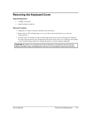
...Removal and Replacement 2-13 Carefully insert a flat-blade screwdriver blade under the keyboard cover near the right end, then near the center, then near the left and right display assembly hinges. CAUTION: Be careful not to damage the antenna PCA that secure the keyboard cover to...present, and then remove the battery. 2. Damaging either antenna PCA can degrade notebook performance. Remove the two M2.5×4.0mm hinge cover screws that is connected to the rear of the cover. Removing the Keyboard Cover Required Equipment • 1 Phillips screwdriver • Small flat-blade screwdriver...
...Removal and Replacement 2-13 Carefully insert a flat-blade screwdriver blade under the keyboard cover near the right end, then near the center, then near the left and right display assembly hinges. CAUTION: Be careful not to damage the antenna PCA that secure the keyboard cover to...present, and then remove the battery. 2. Damaging either antenna PCA can degrade notebook performance. Remove the two M2.5×4.0mm hinge cover screws that is connected to the rear of the cover. Removing the Keyboard Cover Required Equipment • 1 Phillips screwdriver • Small flat-blade screwdriver...
Maintenance and Service Guide
Page 44
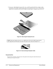
Disconnecting the Speaker Cable Reassembly Note Insert the tabs on the left side of display assembly hinge to be repeated on HP Pavilion 5300 and 5200, HP Compaq nx9010, and Compaq Presario 2500 models, disconnect the speaker cable as indicated in Figure 2-10. This procedure might ... carefully insert the flat-blade screwdriver under the right side of the panel into the mating slots under the keyboard, and then press the panel into place. 2-14 Removal and Replacement Service Manual Removing the Keyboard Cover NOTE: When removing the keyboard cover on the left - Figure 2-10. 4.
Disconnecting the Speaker Cable Reassembly Note Insert the tabs on the left side of display assembly hinge to be repeated on HP Pavilion 5300 and 5200, HP Compaq nx9010, and Compaq Presario 2500 models, disconnect the speaker cable as indicated in Figure 2-10. This procedure might ... carefully insert the flat-blade screwdriver under the right side of the panel into the mating slots under the keyboard, and then press the panel into place. 2-14 Removal and Replacement Service Manual Removing the Keyboard Cover NOTE: When removing the keyboard cover on the left - Figure 2-10. 4.
Maintenance and Service Guide
Page 45
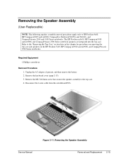
Refer to the top case. 4. Remove the keyboard cover (page 2-13). 3. Required Equipment 1 Phillips screwdriver Removal Procedure 1. Figure 2-11. The HP Pavilion ze5x00, HP Compaq nx9010 and nx9008, and Compaq Presario 2500 Series notebook speakers are integrated into the top case. Unplug the AC... on the HP Pavilion 5x00, HP Compaq nx9010 and nx9008, and Compaq Presario 2500 Series notebooks. Disconnect the 4-wire cable from the switchboard PCA. Removing the Speaker Assembly Service Manual Removal and Replacement 2-15 Removing the Speaker Assembly (User-Replaceable) NOTE: ...
Refer to the top case. 4. Remove the keyboard cover (page 2-13). 3. Required Equipment 1 Phillips screwdriver Removal Procedure 1. Figure 2-11. The HP Pavilion ze5x00, HP Compaq nx9010 and nx9008, and Compaq Presario 2500 Series notebook speakers are integrated into the top case. Unplug the AC... on the HP Pavilion 5x00, HP Compaq nx9010 and nx9008, and Compaq Presario 2500 Series notebooks. Disconnect the 4-wire cable from the switchboard PCA. Removing the Speaker Assembly Service Manual Removal and Replacement 2-15 Removing the Speaker Assembly (User-Replaceable) NOTE: ...
Maintenance and Service Guide
Page 46
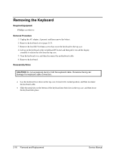
... remove the battery. 2. Reassembly Notes CAUTION: Do not excessively bend or fold the keyboard cable. Lift up on the bottom of the keyboard into their slots in the top case, and then lower the keyboard into place. 2-16 Removal and Replacement Service Manual Turn the keyboard over, and then disconnect the motherboard cable. 6. Remove the...
... remove the battery. 2. Reassembly Notes CAUTION: Do not excessively bend or fold the keyboard cable. Lift up on the bottom of the keyboard into their slots in the top case, and then lower the keyboard into place. 2-16 Removal and Replacement Service Manual Turn the keyboard over, and then disconnect the motherboard cable. 6. Remove the...

Maintenance and Service Guide
Page 47
Figure 2-12. Removing the Keyboard Service Manual Removal and Replacement 2-17
Figure 2-12. Removing the Keyboard Service Manual Removal and Replacement 2-17
Maintenance and Service Guide
Page 48
... the top case and speaker assembly, respectively. 4. Removing the Switchboard PCA HP Pavilion 4x00, HP Compaq nx9005 and nx9000, Compaq Evo Notebook N1050v and N1010v, and Compaq Presario 2100 and 1100 Models 2-18 Removal and Replacement Service Manual Gently lift up on the keyboard, carefully remove the switchboard PCA from the top case, and then disconnect...
... the top case and speaker assembly, respectively. 4. Removing the Switchboard PCA HP Pavilion 4x00, HP Compaq nx9005 and nx9000, Compaq Evo Notebook N1050v and N1010v, and Compaq Presario 2100 and 1100 Models 2-18 Removal and Replacement Service Manual Gently lift up on the keyboard, carefully remove the switchboard PCA from the top case, and then disconnect...
Maintenance and Service Guide
Page 49
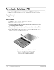
Remove the keyboard cover (page 2-13). 3. Remove the switchboard PCA. Figure 2-14. NOTE: This section applies only to disconnect the PCA from the motherboard. 6. Gently lift up on the rear right edge of the switchboard PCA to HP Pavilion 5x00, HP Compaq nx9010 and nx9008, ...screws that connects the switchboard PCA to the top case. 5. Removing the Switchboard PCA HP Pavilion 5x00, HP Compaw nx9010 and nx9008, and Compaq Presario 2500 Models Service Manual Removal and Replacement 2-19 Required Equipment 1 Phillips screwdriver Removal Procedure 1. Disconnect the 2-wire cable that ...
Remove the keyboard cover (page 2-13). 3. Remove the switchboard PCA. Figure 2-14. NOTE: This section applies only to disconnect the PCA from the motherboard. 6. Gently lift up on the rear right edge of the switchboard PCA to HP Pavilion 5x00, HP Compaq nx9010 and nx9008, ...screws that connects the switchboard PCA to the top case. 5. Removing the Switchboard PCA HP Pavilion 5x00, HP Compaw nx9010 and nx9008, and Compaq Presario 2500 Models Service Manual Removal and Replacement 2-19 Required Equipment 1 Phillips screwdriver Removal Procedure 1. Disconnect the 2-wire cable that ...
Maintenance and Service Guide
Page 50
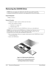
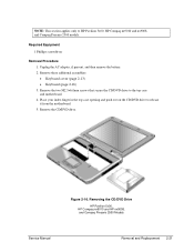
... a M2.5×4.0mm screw. Removing the CD/DVD Drive HP Pavilion 4x00, HP Compaq nx9005 and nx9000, Compaq Evo Notebook N1050v and N1010v, and Compaq Presario 2100 and 1100 Models 2-20 Removal and Replacement Service Manual NOTE: The screws that secure the CD/DVD ...Keyboard cover (page 2-13) • Keyboard (page 2-16) 3. Unplug the AC adapter, if present, and then remove the battery. 2. Remove the 2 screws that secure the CD/DVD drive are installed in the top case opening, and then push out on the CD/DVD drive to HP Pavilion 4x00, HP Compaq nx9005 and nx9000, Compaq Evo Notebook...
... a M2.5×4.0mm screw. Removing the CD/DVD Drive HP Pavilion 4x00, HP Compaq nx9005 and nx9000, Compaq Evo Notebook N1050v and N1010v, and Compaq Presario 2100 and 1100 Models 2-20 Removal and Replacement Service Manual NOTE: The screws that secure the CD/DVD ...Keyboard cover (page 2-13) • Keyboard (page 2-16) 3. Unplug the AC adapter, if present, and then remove the battery. 2. Remove the 2 screws that secure the CD/DVD drive are installed in the top case opening, and then push out on the CD/DVD drive to HP Pavilion 4x00, HP Compaq nx9005 and nx9000, Compaq Evo Notebook...
Maintenance and Service Guide
Page 51
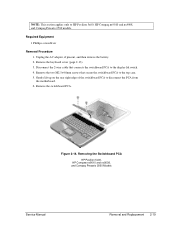
... Removal Procedure 1. Remove the CD/DVD drive. Remove these additional assemblies: • Keyboard cover (page 2-13) • Keyboard (page 2-16) 3. Removing the CD/DVD Drive HP Pavilion 5x00, HP Compaq nx9010 and HP nx9008, and Compaq Presario 2500 Models Service Manual Removal and Replacement 2-21 Remove the two M2.5×6.0mm screws that secure the CD/DVD...
... Removal Procedure 1. Remove the CD/DVD drive. Remove these additional assemblies: • Keyboard cover (page 2-13) • Keyboard (page 2-16) 3. Removing the CD/DVD Drive HP Pavilion 5x00, HP Compaq nx9010 and HP nx9008, and Compaq Presario 2500 Models Service Manual Removal and Replacement 2-21 Remove the two M2.5×6.0mm screws that secure the CD/DVD...
Maintenance and Service Guide
Page 52
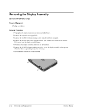
Remove the M2.5×4.0mm screws from the motherboard. 6. Lift the display assembly off of the notebook. 2-22 Removal and Replacement Service Manual Relocate the antenna PCAs away from the notebook rear panel. 4. Remove the two M2.5×6.0mm retaining screws from the display assembly hinges. 5. Remove the... assembly cable from the left hinge.) 7. Unplug the AC adapter, if present, and then remove the battery. 2. Remove the keyboard cover (page 2-13). 3. Removing the Display Assembly (Service Partners Only) Required Equipment 1 Phillips screwdriver Removal Procedure 1.
Remove the M2.5×4.0mm screws from the motherboard. 6. Lift the display assembly off of the notebook. 2-22 Removal and Replacement Service Manual Relocate the antenna PCAs away from the notebook rear panel. 4. Remove the two M2.5×6.0mm retaining screws from the display assembly hinges. 5. Remove the... assembly cable from the left hinge.) 7. Unplug the AC adapter, if present, and then remove the battery. 2. Remove the keyboard cover (page 2-13). 3. Removing the Display Assembly (Service Partners Only) Required Equipment 1 Phillips screwdriver Removal Procedure 1.
Maintenance and Service Guide
Page 54
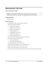
...Remove the two M2.5×4.0mm screws from the motherboard. 2-24 Removal and Replacement Service Manual Remove these additional assemblies: • Hard disk drive (page 2-9) • Keyboard cover (page 2-13) • Speaker assembly (page 2-23) • Keyboard (page 2-16) • Switchboard PCA (page 2-19) • CD/..., and remove the battery. 2. Removing the Top Case (Service Partners Only) NOTE: This section applies only to HP Pavilion 4x00, HP Compaq nx9005 and nx9000, Compaq Evo Notebook N1050v and N1010v, and Compaq Presario 2100 and 1100 models. Lift the top case off of the...
...Remove the two M2.5×4.0mm screws from the motherboard. 2-24 Removal and Replacement Service Manual Remove these additional assemblies: • Hard disk drive (page 2-9) • Keyboard cover (page 2-13) • Speaker assembly (page 2-23) • Keyboard (page 2-16) • Switchboard PCA (page 2-19) • CD/..., and remove the battery. 2. Removing the Top Case (Service Partners Only) NOTE: This section applies only to HP Pavilion 4x00, HP Compaq nx9005 and nx9000, Compaq Evo Notebook N1050v and N1010v, and Compaq Presario 2100 and 1100 models. Lift the top case off of the...
Maintenance and Service Guide
Page 56
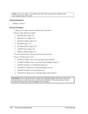
NOTE: This section applies only to the notebook. 2-26 Removal and Replacement Service Manual Remove these additional assemblies: • Hard disk drive (page 2-9) • Keyboard cover (page 2-13) • Speaker assembly (page 2-15) • Keyboard (page 2-16) • Switchboard PCA (page 2-19) • CD/DVD drive (page 2-20) • Display ...0mm screws on the front edge of each screw as it is removed and install it in damage to HP Pavilion 5x00, HP Compaq nx9010 and HP nx9008, and Compaq Presario 2500 models. Unplug the AC adapter, if present, and then remove the battery. 2.
NOTE: This section applies only to the notebook. 2-26 Removal and Replacement Service Manual Remove these additional assemblies: • Hard disk drive (page 2-9) • Keyboard cover (page 2-13) • Speaker assembly (page 2-15) • Keyboard (page 2-16) • Switchboard PCA (page 2-19) • CD/DVD drive (page 2-20) • Display ...0mm screws on the front edge of each screw as it is removed and install it in damage to HP Pavilion 5x00, HP Compaq nx9010 and HP nx9008, and Compaq Presario 2500 models. Unplug the AC adapter, if present, and then remove the battery. 2.
Maintenance and Service Guide
Page 59
... the motherboard. 6. Remove these additional assemblies: • Hard disk drive (page 2-9) • Keyboard cover (page 2-13) • Keyboard (page 2-16) • Switchboard PCA (page 2-19) • Display assembly (page 2-23...HP Pavilion ze4x00, HP Compaq nx9005 and nx9000, Compaq Evo Notebook N1050v and N1010v, and Compaq Presario 2100 and 1100 models. Remove the floppy drive. Unplug the AC adapter, if present, and remove the battery. 2. Required Equipment 1 Phillips screwdriver Removal Procedure 1. Disconnect the motherboard cable. 5. Service Manual Removal and Replacement...
... the motherboard. 6. Remove these additional assemblies: • Hard disk drive (page 2-9) • Keyboard cover (page 2-13) • Keyboard (page 2-16) • Switchboard PCA (page 2-19) • Display assembly (page 2-23...HP Pavilion ze4x00, HP Compaq nx9005 and nx9000, Compaq Evo Notebook N1050v and N1010v, and Compaq Presario 2100 and 1100 models. Remove the floppy drive. Unplug the AC adapter, if present, and remove the battery. 2. Required Equipment 1 Phillips screwdriver Removal Procedure 1. Disconnect the motherboard cable. 5. Service Manual Removal and Replacement...
Maintenance and Service Guide
Page 61
Service Manual Removal and Replacement 2-31 NOTE: This section applies only to the top case. 5. Required Equipment • 1 Phillips screwdriver Removal Procedure 1. Remove these additional assemblies: • Hard disk drive (page 2-9) • Keyboard cover (page 2-13) • Keyboard (page 2-16) &#...8226; Switchboard PCA (page 2-19) • Display assembly (page 2-23) • Top case (page 2-26) 3. Remove the four M2.5×6.0mm screws that secure the floppy drive and floppy drive bezel to HP Pavilion 5x00, HP...
Service Manual Removal and Replacement 2-31 NOTE: This section applies only to the top case. 5. Required Equipment • 1 Phillips screwdriver Removal Procedure 1. Remove these additional assemblies: • Hard disk drive (page 2-9) • Keyboard cover (page 2-13) • Keyboard (page 2-16) &#...8226; Switchboard PCA (page 2-19) • Display assembly (page 2-23) • Top case (page 2-26) 3. Remove the four M2.5×6.0mm screws that secure the floppy drive and floppy drive bezel to HP Pavilion 5x00, HP...
Maintenance and Service Guide
Page 63
Removing the Infrared (I/R) PCA (Service Partners Only) Required Equipment 1 Phillips screwdriver Removal Procedure 1. Unplug the AC adapter, if present, and then remove the battery. 2. Remove these additional assemblies: • Hard disk drive (page 2-9) • Keyboard cover (page 2-13) • Keyboard (page 2-16) • Switchboard PCA (page 2-19) • Display assembly (page 2-23) • Top case (page 2-26) Service Manual Removal and Replacement 2-33
Removing the Infrared (I/R) PCA (Service Partners Only) Required Equipment 1 Phillips screwdriver Removal Procedure 1. Unplug the AC adapter, if present, and then remove the battery. 2. Remove these additional assemblies: • Hard disk drive (page 2-9) • Keyboard cover (page 2-13) • Keyboard (page 2-16) • Switchboard PCA (page 2-19) • Display assembly (page 2-23) • Top case (page 2-26) Service Manual Removal and Replacement 2-33
Maintenance and Service Guide
Page 65
...2-9) • Keyboard cover (page 2-13) • Keyboard (page 2-16) • Switchboard PCA (page 2-19) • Display assembly (page 2-23) • Top case (page 2-26) 3. Remove the two M2.0×3.0mm flathead screws that secure the audio PCA shield to HP Pavilion 5300 and 5200, HP Compaq nx9010, and... Compaq Presario 2500 models. Disconnect the audio PCA cable from the clip on the bottom case. 5. Service Manual Removal and Replacement 2-35 Remove the audio PCA cable from the ...
...2-9) • Keyboard cover (page 2-13) • Keyboard (page 2-16) • Switchboard PCA (page 2-19) • Display assembly (page 2-23) • Top case (page 2-26) 3. Remove the two M2.0×3.0mm flathead screws that secure the audio PCA shield to HP Pavilion 5300 and 5200, HP Compaq nx9010, and... Compaq Presario 2500 models. Disconnect the audio PCA cable from the clip on the bottom case. 5. Service Manual Removal and Replacement 2-35 Remove the audio PCA cable from the ...


