Start Here Guide
Page 10
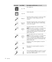
...Universal Serial Bus (USB) 2.0 connector to connect to a microphone. You must use the Audio In connector, which is connected to the motherboard and located on the back of the computer, to record audio only. (Select models only.) Secondary Right audio input connector (red). NOTE...: This Audio In connector is connected to the TV tuner. Connector Icon/label Description and function (continued) Rear speaker out Center/subwoofer Secondary S-video connector to connect your VCR, S-video S-Video 2 video camera, or other analog source to the computer. Microphone In...
...Universal Serial Bus (USB) 2.0 connector to connect to a microphone. You must use the Audio In connector, which is connected to the motherboard and located on the back of the computer, to record audio only. (Select models only.) Secondary Right audio input connector (red). NOTE...: This Audio In connector is connected to the TV tuner. Connector Icon/label Description and function (continued) Rear speaker out Center/subwoofer Secondary S-video connector to connect your VCR, S-video S-Video 2 video camera, or other analog source to the computer. Microphone In...
Start Here Guide
Page 12
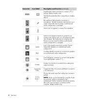
Center Rear Audio Line In (blue) connector to connect to a TV set -top box connector ... for input into computer. Some computers include this Audio In connector, which is activated. The Mic connector also functions as a center/subwoofer Line Out when a multichannel audio configuration is connected to connect from set -top box. Audio Line Out (green) to... C/Sub (gold) connector to a microphone. Microphone In (Mic) (pink) to connect to connect Center/ Subwoofer speakers in a multichannel audio configuration. S-Video Composite Video A/V In Audio 1 L S-video In connector to the...
Center Rear Audio Line In (blue) connector to connect to a TV set -top box connector ... for input into computer. Some computers include this Audio In connector, which is activated. The Mic connector also functions as a center/subwoofer Line Out when a multichannel audio configuration is connected to connect from set -top box. Audio Line Out (green) to... C/Sub (gold) connector to a microphone. Microphone In (Mic) (pink) to connect to connect Center/ Subwoofer speakers in a multichannel audio configuration. S-Video Composite Video A/V In Audio 1 L S-video In connector to the...

Start Here Guide
Page 13
... be recorded by using this primary right audio input connector on the TV tuner card. VGA Monitor/VGA (blue) display output connector connects to the motherboard. You may want to extend the ends of the computer. (Select models only.) TV In (TV antenna or cable input from set -top box.) FM...
... be recorded by using this primary right audio input connector on the TV tuner card. VGA Monitor/VGA (blue) display output connector connects to the motherboard. You may want to extend the ends of the computer. (Select models only.) TV In (TV antenna or cable input from set -top box.) FM...
Upgrading and Servicing Guide
Page 13
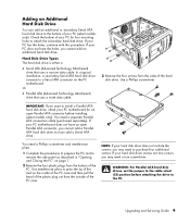
... cable. 3 Remove the four screws from the sides of the hard disk drive. You need to press the tip of the stud on the PC motherboard. Use needle-nose pliers to purchase four additional screws. In a typical installation, a secondary Serial ATA hard disk drive connects to a Serial ATA... disk drive, but can add an additional or secondary Serial ATA hard disk drive to attach the secondary hard disk drive. NOTE: If your PC motherboard does not have the holes, you may need a separate Parallel ATA connection cable (purchased separately). WARNING: For Parallel ATA hard disk drives, ...
... cable. 3 Remove the four screws from the sides of the hard disk drive. You need to press the tip of the stud on the PC motherboard. Use needle-nose pliers to purchase four additional screws. In a typical installation, a secondary Serial ATA hard disk drive connects to a Serial ATA... disk drive, but can add an additional or secondary Serial ATA hard disk drive to attach the secondary hard disk drive. NOTE: If your PC motherboard does not have the holes, you may need a separate Parallel ATA connection cable (purchased separately). WARNING: For Parallel ATA hard disk drives, ...
Upgrading and Servicing Guide
Page 15
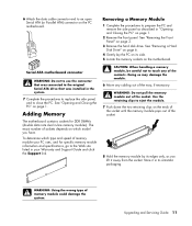
...WARNING: Do not pull the memory module out of memory module could damage the system. Adding Memory The motherboard contains sockets for DDR DIMMs (double data rate dual in your PC uses, and for specific memory module information and specifications, go to eject the module. 7 Push down ...the two retaining clips on the PC motherboard. Store it away from the socket. See "Opening and Closing the PC" on page 3. 3 Remove the hard disk drive. Upgrading and Servicing Guide 11 See "Removing a Hard Disk...
...WARNING: Do not pull the memory module out of memory module could damage the system. Adding Memory The motherboard contains sockets for DDR DIMMs (double data rate dual in your PC uses, and for specific memory module information and specifications, go to eject the module. 7 Push down ...the two retaining clips on the PC motherboard. Store it away from the socket. See "Opening and Closing the PC" on page 3. 3 Remove the hard disk drive. Upgrading and Servicing Guide 11 See "Removing a Hard Disk...
Upgrading and Servicing Guide
Page 17
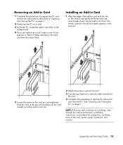
... an Add-in Card 1 Complete the procedures to prepare the PC and remove the side panel as described in "Opening and Closing the PC" on page 1. 2 Gently lay the PC on its side. 3 Inside the PC, locate the add-in card slots on the motherboard. 4 If you are replacing a card, make a note of any... external or internal cables attached to the card. 4 Complete the procedures to replace the side panel and close the PC.
... an Add-in Card 1 Complete the procedures to prepare the PC and remove the side panel as described in "Opening and Closing the PC" on page 1. 2 Gently lay the PC on its side. 3 Inside the PC, locate the add-in card slots on the motherboard. 4 If you are replacing a card, make a note of any... external or internal cables attached to the card. 4 Complete the procedures to replace the side panel and close the PC.
Upgrading and Servicing Guide
Page 18
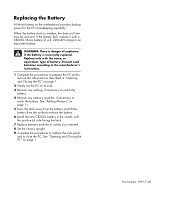
.... 8 Set the chassis upright. 9 Complete the procedures to replace the side panel, and to close the PC. See "Opening and Closing the PC" on the motherboard provides backup power for the PC's timekeeping capability. Part Number: 5991-7140 WARNING: There is incorrectly replaced. If the battery fails, replace it...battery and lift the battery from the socket to release the battery. 6 Install the new CR2032 battery in "Opening and Closing the PC" on page 1. 2 Gently lay the PC on its side. 3 Remove any cabling, if necessary, to reach the battery. 4 Remove any memory modules, if necessary, to...
.... 8 Set the chassis upright. 9 Complete the procedures to replace the side panel, and to close the PC. See "Opening and Closing the PC" on the motherboard provides backup power for the PC's timekeeping capability. Part Number: 5991-7140 WARNING: There is incorrectly replaced. If the battery fails, replace it...battery and lift the battery from the socket to release the battery. 6 Install the new CR2032 battery in "Opening and Closing the PC" on page 1. 2 Gently lay the PC on its side. 3 Remove any cabling, if necessary, to reach the battery. 4 Remove any memory modules, if necessary, to...

