Service Manual
Page 7
......72 I/O cover ...72 Top, right cover ...73 Top cover ...74 Front, right cover ...75 Control panel ...78 Formatter ...80 Fuser ...83 Laser/scanner ...86 Engine control unit (ECU) ...88 Access plate ...96 High-voltage power supply ...97 Paper feed guide assembly ...104 Main motor ...106... notes for the gear assembly 110 Tray 1 solenoid ...111 Tray 2 solenoid ...112 E-label reader (memory tag) ...113 Face-down-roller shaft ...115 Cartridge door ...117 Transfer roller ...120 Registration assembly ...121 Tray 1 pickup roller ...124 Tray 2 pickup roller ...125 Separation pad ...127 ENWW v
......72 I/O cover ...72 Top, right cover ...73 Top cover ...74 Front, right cover ...75 Control panel ...78 Formatter ...80 Fuser ...83 Laser/scanner ...86 Engine control unit (ECU) ...88 Access plate ...96 High-voltage power supply ...97 Paper feed guide assembly ...104 Main motor ...106... notes for the gear assembly 110 Tray 1 solenoid ...111 Tray 2 solenoid ...112 E-label reader (memory tag) ...113 Face-down-roller shaft ...115 Cartridge door ...117 Transfer roller ...120 Registration assembly ...121 Tray 1 pickup roller ...124 Tray 2 pickup roller ...125 Separation pad ...127 ENWW v
Service Manual
Page 16
... Removing the registration assembly (2 of 3 122 Figure 5-56 Removing the registration assembly (3 of 3 123 Figure 5-57 Removing the tray 1 pickup roller 124 Figure 5-58 Removing the tray 2 pickup roller (1 of 2 125 Figure 5-59 Removing the tray 2 pickup roller (2 of 2 126 Figure 5-60 Removing the separation pad ...127 Figure 6-1 Jam-detection sensors ...150 Figure 6-2 Jetdirect page ...158...
... Removing the registration assembly (2 of 3 122 Figure 5-56 Removing the registration assembly (3 of 3 123 Figure 5-57 Removing the tray 1 pickup roller 124 Figure 5-58 Removing the tray 2 pickup roller (1 of 2 125 Figure 5-59 Removing the tray 2 pickup roller (2 of 2 126 Figure 5-60 Removing the separation pad ...127 Figure 6-1 Jam-detection sensors ...150 Figure 6-2 Jetdirect page ...158...
Service Manual
Page 65
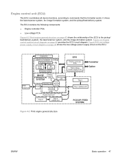
... 48 provides the ECU circuit diagram. Rear output bin Output bin LASER/SCANNER SYSTEM Scanning mirror Laser diode BD circuit Scanner motor IMAGE Primary charging FORMATION roller SYSTEM Developing unit Fuser PhotoCleaning unit sensitive drum Transfer charging roller Duplex feed unit Tray 2 Tray 2 pickup unit ECU Engine controller PCA High-voltage Power supply PCA Formatter...
... 48 provides the ECU circuit diagram. Rear output bin Output bin LASER/SCANNER SYSTEM Scanning mirror Laser diode BD circuit Scanner motor IMAGE Primary charging FORMATION roller SYSTEM Developing unit Fuser PhotoCleaning unit sensitive drum Transfer charging roller Duplex feed unit Tray 2 Tray 2 pickup unit ECU Engine controller PCA High-voltage Power supply PCA Formatter...
Service Manual
Page 68
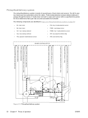
...detection sensors detect media as it passes through the device. The ECU uses two motors and two solenoids to drive the rollers. The following components are identified in Figure 4-5 Pickup/feed/delivery system on page 50: ● M1, main motor ● M2, fuser motor ● SL1, tray...PS902, tray 1 media-detection sensor ● SR1, top output-bin delivery flag ● SR2, fuser-delivery flag Figure 4-5 Pickup/feed/delivery system 50 Chapter 4 Theory of feed rollers and sensors. If media does not reach or pass each sensor within a specified time period, the ECU determines that a jam has...
...detection sensors detect media as it passes through the device. The ECU uses two motors and two solenoids to drive the rollers. The following components are identified in Figure 4-5 Pickup/feed/delivery system on page 50: ● M1, main motor ● M2, fuser motor ● SL1, tray...PS902, tray 1 media-detection sensor ● SR1, top output-bin delivery flag ● SR2, fuser-delivery flag Figure 4-5 Pickup/feed/delivery system 50 Chapter 4 Theory of feed rollers and sensors. If media does not reach or pass each sensor within a specified time period, the ECU determines that a jam has...

Service Manual
Page 74
Internal components Figure 4-15 Cross-section of device on page 56 highlights the major internal components. 1 2 3 4 56 7 8 18 17 16 15 14 13 12 11 10 9 Figure 4-15 Cross-section of device 1 Top output-bin delivery roller 2 Fuser roller, fuser assembly 3 Laser/scanner 4 Photosensitive drum, print cartridge 5 Print cartridge 6 Registration assembly 7 Tray 1 pickup roller 56 Chapter 4 Theory of operation ENWW
Internal components Figure 4-15 Cross-section of device on page 56 highlights the major internal components. 1 2 3 4 56 7 8 18 17 16 15 14 13 12 11 10 9 Figure 4-15 Cross-section of device 1 Top output-bin delivery roller 2 Fuser roller, fuser assembly 3 Laser/scanner 4 Photosensitive drum, print cartridge 5 Print cartridge 6 Registration assembly 7 Tray 1 pickup roller 56 Chapter 4 Theory of operation ENWW

Service Manual
Page 76
... INTR. INTR (initial rotation) From the time of the print command until the pickup Prepares the photosensitive drum for a complete description of the WAIT (power-on Failure/abnormality check: detection of laser/scanner failure, fuser failure, and open covers Communication with the memory tag 58 Chapter...Cleaning of the media. See Table 4-2 Power-on sequence on the photosensitive drum and sensor detects the trailing edge of the transfer roller after the primary charging AC bias is turned off. Table 4-1 Operation sequences Name Timing Purpose WAIT From power-on until the top...
... INTR. INTR (initial rotation) From the time of the print command until the pickup Prepares the photosensitive drum for a complete description of the WAIT (power-on Failure/abnormality check: detection of laser/scanner failure, fuser failure, and open covers Communication with the memory tag 58 Chapter...Cleaning of the media. See Table 4-2 Power-on sequence on the photosensitive drum and sensor detects the trailing edge of the transfer roller after the primary charging AC bias is turned off. Table 4-1 Operation sequences Name Timing Purpose WAIT From power-on until the top...
Service Manual
Page 81
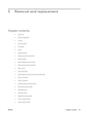
...and replacement Chapter contents ● Overview ● Service approach ● Covers ● Control panel ● Formatter ● Fuser ● Laser/scanner ● Engine control unit (ECU) ● Access plate ● High-voltage power supply ● Paper feed guide assembly ●...notes for the gear assembly ● Tray 1 solenoid ● Tray 2 solenoid ● E-label reader (memory tag) ● Face-down-roller shaft ● Cartridge door ● Transfer roller ● Registration assembly ● Tray 1 pickup roller ● Tray 2 pickup roller ENWW Chapter contents 63
...and replacement Chapter contents ● Overview ● Service approach ● Covers ● Control panel ● Formatter ● Fuser ● Laser/scanner ● Engine control unit (ECU) ● Access plate ● High-voltage power supply ● Paper feed guide assembly ●...notes for the gear assembly ● Tray 1 solenoid ● Tray 2 solenoid ● E-label reader (memory tag) ● Face-down-roller shaft ● Cartridge door ● Transfer roller ● Registration assembly ● Tray 1 pickup roller ● Tray 2 pickup roller ENWW Chapter contents 63

Service Manual
Page 142
Rotate the top of the roller off of the shaft, and then lift the roller out of the tray 1 pickup roller to release the roller. 1 Figure 5-57 Removing the tray 1 pickup roller 2. Spread the pickup-roller locks (callout 1) on each side of the device. 124 Chapter 5 Removal and replacement ENWW Tray 1 pickup roller 1.
Rotate the top of the roller off of the shaft, and then lift the roller out of the tray 1 pickup roller to release the roller. 1 Figure 5-57 Removing the tray 1 pickup roller 2. Spread the pickup-roller locks (callout 1) on each side of the device. 124 Chapter 5 Removal and replacement ENWW Tray 1 pickup roller 1.

Service Manual
Page 143
Tray 2 pickup roller NOTE Also follow these instructions to the left. 4. Tip the device over on each side of the roller downward. 1 Figure 5-58 Removing the tray 2 pickup roller (1 of the device facing you. 2. Slide the roller and shaft toward the left -side bushing by sliding the bushing to remove any optional-tray pickup rollers. 1. ENWW Tray 2 pickup roller 125 Remove the left until they clear the hole in the right-side bushing, and then lift the right end of the shaft. Rotate the bushings (callout 1) on its rear side, with the bottom of 2) 3.
Tray 2 pickup roller NOTE Also follow these instructions to the left. 4. Tip the device over on each side of the roller downward. 1 Figure 5-58 Removing the tray 2 pickup roller (1 of the device facing you. 2. Slide the roller and shaft toward the left -side bushing by sliding the bushing to remove any optional-tray pickup rollers. 1. ENWW Tray 2 pickup roller 125 Remove the left until they clear the hole in the right-side bushing, and then lift the right end of the shaft. Rotate the bushings (callout 1) on its rear side, with the bottom of 2) 3.

Service Manual
Page 144
5. Figure 5-59 Removing the tray 2 pickup roller (2 of the device. Slide the roller and shaft toward the right, and then lift the roller and shaft together out of 2) 126 Chapter 5 Removal and replacement ENWW
5. Figure 5-59 Removing the tray 2 pickup roller (2 of the device. Slide the roller and shaft toward the right, and then lift the roller and shaft together out of 2) 126 Chapter 5 Removal and replacement ENWW
Service Manual
Page 150
... paper path. 2. When energized, solenoid SL2 releases a clutch, and then the pick-up roller rotates to see if the pick-up roller is installed in connector J510 on . Verify that a genuine HP print cartridge is rotating. 5. Verify that the tray 2 pickup roller and separation pad are installed correctly. 132 Chapter 6 Troubleshooting ENWW If you turn...
... paper path. 2. When energized, solenoid SL2 releases a clutch, and then the pick-up roller rotates to see if the pick-up roller is installed in connector J510 on . Verify that a genuine HP print cartridge is rotating. 5. Verify that the tray 2 pickup roller and separation pad are installed correctly. 132 Chapter 6 Troubleshooting ENWW If you turn...
Service Manual
Page 152
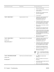
...the guides are using meet HP specifications. (See Media specifications on page 13.) 2. Remove any media from the rear of media. 3. Lift the metal flap, and then remove any media. 4. Verify that the type and quality of the media that the tray 2 pickup roller and separation pad are ...not too tight or too loose against the stack of the media that the tray pickup roller and separation pad are using meet HP specifications. (See Media specifications on page 13.) 2. Verify that the media is jammed in the tray indicated. Recommended action 3. Verify that...
...the guides are using meet HP specifications. (See Media specifications on page 13.) 2. Remove any media from the rear of media. 3. Lift the metal flap, and then remove any media. 4. Verify that the type and quality of the media that the tray 2 pickup roller and separation pad are ...not too tight or too loose against the stack of the media that the tray pickup roller and separation pad are using meet HP specifications. (See Media specifications on page 13.) 2. Verify that the media is jammed in the tray indicated. Recommended action 3. Verify that...

Service Manual
Page 242
Alphabetical parts list Table 7-9 Alphabetical parts list Description Arm, door Arm, pad Arm, paper-width sensor Bottom plate roller assembly Bushing Bushing, inner Bushing, transfer, right Cable, memory tag Cable, option interface Cable, paper delivery sensor Cable, scanner motor Cable, tray... 6) on page 207 Internal components (6 of 6) on page 221 Internal components (3 of 6) on page 215 Internal components (1 of 6) on page 207 Tray 2 pickup assembly on page 223 Internal components (2 of 6) on page 211 Internal components (1 of 6) on page 207 Covers on page 205 Internal components (1 of 6) on ...
Alphabetical parts list Table 7-9 Alphabetical parts list Description Arm, door Arm, pad Arm, paper-width sensor Bottom plate roller assembly Bushing Bushing, inner Bushing, transfer, right Cable, memory tag Cable, option interface Cable, paper delivery sensor Cable, scanner motor Cable, tray... 6) on page 207 Internal components (6 of 6) on page 221 Internal components (3 of 6) on page 215 Internal components (1 of 6) on page 207 Tray 2 pickup assembly on page 223 Internal components (2 of 6) on page 211 Internal components (1 of 6) on page 207 Covers on page 205 Internal components (1 of 6) on ...

Service Manual
Page 248
Table 7-9 Alphabetical parts list (continued) Description Registration assembly Ring, E Ring, E roller stay assembly Roller, face-down Roller, multipurpose pick-up Roller, tray 2 paper pickup Saddle, wire Saddle, wire Screw, D, M3x8 Screw, D, M3x8 Screw, D, M3x8 Screw, D, M3x8 Screw, D, M3x8 Screw, tap, M3x6 ...page 211 Internal components (5 of 6) on page 219 Internal components (6 of 6) on page 221 Internal components (3 of 6) on page 215 Tray 2 pickup assembly on page 223 Internal components (1 of 6) on page 207 Internal components (5 of 6) on page 219 Internal components (1 of 6) on page 207...
Table 7-9 Alphabetical parts list (continued) Description Registration assembly Ring, E Ring, E roller stay assembly Roller, face-down Roller, multipurpose pick-up Roller, tray 2 paper pickup Saddle, wire Saddle, wire Screw, D, M3x8 Screw, D, M3x8 Screw, D, M3x8 Screw, D, M3x8 Screw, D, M3x8 Screw, tap, M3x6 ...page 211 Internal components (5 of 6) on page 219 Internal components (6 of 6) on page 221 Internal components (3 of 6) on page 215 Tray 2 pickup assembly on page 223 Internal components (1 of 6) on page 207 Internal components (5 of 6) on page 219 Internal components (1 of 6) on page 207...

Service Manual
Page 250
...cartridge, right Stopper, feed guide, left Stopper, fuser thrust Stopper, gear Switch, front Top cover assembly Top sensor PCA (PS901) Transfer roller assembly Tray 2 pickup assembly Tray 2 pickup roller assembly Washer, plain Part number RU5-2386-000 RC2-0665-000 RC2-0593-000 RC1-4126-000 RC2-0707-000 RC2-0702-000...components (6 of 6) on page 221 Covers on page 205 Internal components (4 of 6) on page 217 Internal components (3 of 6) on page 215 Tray 2 pickup assembly on page 223 Tray 2 pickup assembly on page 223 Internal components (2 of 6) on page 211 232 Chapter 7 Parts and diagrams ENWW
...cartridge, right Stopper, feed guide, left Stopper, fuser thrust Stopper, gear Switch, front Top cover assembly Top sensor PCA (PS901) Transfer roller assembly Tray 2 pickup assembly Tray 2 pickup roller assembly Washer, plain Part number RU5-2386-000 RC2-0665-000 RC2-0593-000 RC1-4126-000 RC2-0707-000 RC2-0702-000...components (6 of 6) on page 221 Covers on page 205 Internal components (4 of 6) on page 217 Internal components (3 of 6) on page 215 Tray 2 pickup assembly on page 223 Tray 2 pickup assembly on page 223 Internal components (2 of 6) on page 211 232 Chapter 7 Parts and diagrams ENWW

Service Manual
Page 255
... RL1-1367-000 RL1-1370-000 Cover, right front Roller, tray 2 paper pickup RM1-1485-000 roller stay assembly RM1-1490-000 RM1-1497-000 Multipurpose tray assembly Delivery roller assembly RM1-1506-000 Oblique roller assembly RM1-1508-000 Transfer roller assembly RM1-1521-030 Laser/scanner assembly RM1-1522-000 Drive release assembly RM1-3712...
... RL1-1367-000 RL1-1370-000 Cover, right front Roller, tray 2 paper pickup RM1-1485-000 roller stay assembly RM1-1490-000 RM1-1497-000 Multipurpose tray assembly Delivery roller assembly RM1-1506-000 Oblique roller assembly RM1-1508-000 Transfer roller assembly RM1-1521-030 Laser/scanner assembly RM1-1522-000 Drive release assembly RM1-3712...

Service Manual
Page 256
... RM1-3727-000 Top cover assembly Left cover assembly Cartridge-door assembly Multipurpose cover assembly Rear cover assembly Control-panel assembly Bottom plate roller assembly RM1-3730-000 Engine controller assembly - 110-127V RM1-3731-000 Engine controller assembly - 220-240V RM1-3740-000 Fuser ... feed assembly RM1-3760-000 Paper feed guide assembly RM1-3762-000 Paper pick-up assembly RM1-3762-000 Tray 2 pickup assembly RM1-3763-000 Tray 2 pickup roller assembly RM1-3769-000 Sensor-flag assembly 238 Chapter 7 Parts and diagrams Table and page Internal components (3 of 6) ...
... RM1-3727-000 Top cover assembly Left cover assembly Cartridge-door assembly Multipurpose cover assembly Rear cover assembly Control-panel assembly Bottom plate roller assembly RM1-3730-000 Engine controller assembly - 110-127V RM1-3731-000 Engine controller assembly - 220-240V RM1-3740-000 Fuser ... feed assembly RM1-3760-000 Paper feed guide assembly RM1-3762-000 Paper pick-up assembly RM1-3762-000 Tray 2 pickup assembly RM1-3763-000 Tray 2 pickup roller assembly RM1-3769-000 Sensor-flag assembly 238 Chapter 7 Parts and diagrams Table and page Internal components (3 of 6) ...
Service Manual
Page 287
...141 physical specifications 18, 244 pickup assembly, diagrams 190 pickup roller, tray 1 locating 56 removing 124 pickup roller, tray 2 locating 56 removing 125 pickup/feed/delivery operations 50 PIN codes, service 161 ports included 2 locating 6 supported 3 troubleshooting 157 PostScript Printer Description (PPD) files included ... 11 pressure roller 56 primary charging stage 53 print cartridge door, removing 117 print cartridge status HP Easy Printer Care software 40 print cartridges authentication 35 EconoMode 34 features 4 genuine HP 34 jams, clearing 153 memory tag 61 non-HP 34 operations 52...
...141 physical specifications 18, 244 pickup assembly, diagrams 190 pickup roller, tray 1 locating 56 removing 124 pickup roller, tray 2 locating 56 removing 125 pickup/feed/delivery operations 50 PIN codes, service 161 ports included 2 locating 6 supported 3 troubleshooting 157 PostScript Printer Description (PPD) files included ... 11 pressure roller 56 primary charging stage 53 print cartridge door, removing 117 print cartridge status HP Easy Printer Care software 40 print cartridges authentication 35 EconoMode 34 features 4 genuine HP 34 jams, clearing 153 memory tag 61 non-HP 34 operations 52...

Service Manual
Page 288
...minute 2 troubleshooting 172 spots, troubleshooting 180, 187 statement sizes supported 14 static precautions 65 status embedded Web server 41 HP Easy Printer Care software 40 HP Printer Utility, Macintosh 44 messages, types of 131 status, supplies control panel messages 7 Stop button 7 stopped printing, ...73 total page count 162 transfer roller locating 56 removing 120 transfer stage 54 transfer unit warranty 249 transmission errors 136 transparencies sizes supported 15 tray 1 jams, clearing 151 locating 5 parts diagrams 191 pickup roller, removing 124 rollers 56 sensors 50, 192 270 Index...
...minute 2 troubleshooting 172 spots, troubleshooting 180, 187 statement sizes supported 14 static precautions 65 status embedded Web server 41 HP Easy Printer Care software 40 HP Printer Utility, Macintosh 44 messages, types of 131 status, supplies control panel messages 7 Stop button 7 stopped printing, ...73 total page count 162 transfer roller locating 56 removing 120 transfer stage 54 transfer unit warranty 249 transmission errors 136 transparencies sizes supported 15 tray 1 jams, clearing 151 locating 5 parts diagrams 191 pickup roller, removing 124 rollers 56 sensors 50, 192 270 Index...
Service Manual
Page 289
...diagrams 193 solenoid, removing 111 See also trays tray 2 jams, clearing 151 loading 21 locating 5 part numbers 222 parts diagrams 191 pickup roller, removing 125 rollers 56 sensors 50, 192 solenoid, diagrams 193 solenoid, removing 112 See also trays tray 3 jams, clearing 151 part number 201 physical ...and fuser 249 wavy paper, troubleshooting 172, 185 Web Jetadmin firmware updates 169 Web sites customer support 250 fraud reports 35 HP Easy Printer Care 10 HP Web Jetadmin, downloading 43 Linux support 10 Macintosh customer support 251 Material Safety Data Sheet (MSDS) 259 ordering supplies 200 ...
...diagrams 193 solenoid, removing 111 See also trays tray 2 jams, clearing 151 loading 21 locating 5 part numbers 222 parts diagrams 191 pickup roller, removing 125 rollers 56 sensors 50, 192 solenoid, diagrams 193 solenoid, removing 112 See also trays tray 3 jams, clearing 151 part number 201 physical ...and fuser 249 wavy paper, troubleshooting 172, 185 Web Jetadmin firmware updates 169 Web sites customer support 250 fraud reports 35 HP Easy Printer Care 10 HP Web Jetadmin, downloading 43 Linux support 10 Macintosh customer support 251 Material Safety Data Sheet (MSDS) 259 ordering supplies 200 ...


