
HP LaserJet Pro CP1520 - Software Technical Reference
Page 55
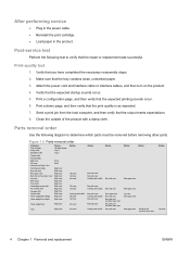
... of the paper types listed in better print quality when printing on the Paper Types screen. The product speed and fuser temperature are non-specific. Paper Types Use the Paper Types pane to configure the standard print modes that are adjusted to the various paper types. ... 105-130g/m2 Glossy Mode 131-175g/m2 Heavy Glossy Mode 176-220g/m2 Print Speed Full speed 3/4 speed 3/4 speed Full speed 3/4 speed 3/4 speed 3/4 speed Color Tables Plain Plain Plain Plain Glossy Glossy Glossy ENWW...
... of the paper types listed in better print quality when printing on the Paper Types screen. The product speed and fuser temperature are non-specific. Paper Types Use the Paper Types pane to configure the standard print modes that are adjusted to the various paper types. ... 105-130g/m2 Glossy Mode 131-175g/m2 Heavy Glossy Mode 176-220g/m2 Print Speed Full speed 3/4 speed 3/4 speed Full speed 3/4 speed 3/4 speed 3/4 speed Color Tables Plain Plain Plain Plain Glossy Glossy Glossy ENWW...
HP LaserJet Pro CP1520 - Software Technical Reference
Page 192
...type 164 Euro symbol 134 Event Log page, EWS (Windows) 65 Event Log screen, HP ToolboxFX 27 EWS (Windows) accessing 57 Advanced page 74 Color Usage Log 65 Device Configuration page 60 Device Information page 66 Device Status page 58 ...printer driver 103 TrueType settings, printer drivers 102 Upload Fonts, HP Printer Utility 154 upload, Configuration Settings menu 154 Windows 78, 80 fonts, external install 131 remove 132 Form to Tray Assignment, drivers 129 formatter number 22 Front to Back printing, printer drivers 103 fuser modes 41 G grayscale settings, HP postscript level 3 emulation printer...
...type 164 Euro symbol 134 Event Log page, EWS (Windows) 65 Event Log screen, HP ToolboxFX 27 EWS (Windows) accessing 57 Advanced page 74 Color Usage Log 65 Device Configuration page 60 Device Information page 66 Device Status page 58 ...printer driver 103 TrueType settings, printer drivers 102 Upload Fonts, HP Printer Utility 154 upload, Configuration Settings menu 154 Windows 78, 80 fonts, external install 131 remove 132 Form to Tray Assignment, drivers 129 formatter number 22 Front to Back printing, printer drivers 103 fuser modes 41 G grayscale settings, HP postscript level 3 emulation printer...
HP LaserJet Pro CP1520 - User Guide
Page 12
...locations 126 Jam in Tray 1 127 Jam in Tray 2 129 Jam in the fuser area 130 Jam in the output bin 131 Solve image quality problems ...132 Use the correct paper type setting in the printer driver 132 Change the paper type setting for Windows 132 Change the paper type ...setting for Mac 132 Adjust color settings in the printer driver 133 Change the color theme for a print job 133 Change the color options 133 Use paper that meets HP specifications 134 Print a cleaning page ...135 Calibrate the product to align the...
...locations 126 Jam in Tray 1 127 Jam in Tray 2 129 Jam in the fuser area 130 Jam in the output bin 131 Solve image quality problems ...132 Use the correct paper type setting in the printer driver 132 Change the paper type setting for Windows 132 Change the paper type ...setting for Mac 132 Adjust color settings in the printer driver 133 Change the color theme for a print job 133 Change the color options 133 Use paper that meets HP specifications 134 Print a cleaning page ...135 Calibrate the product to align the...
HP LaserJet Pro CP1520 - User Guide
Page 58
It is possible for the product, requiring repair. CAUTION: HP LaserJet products use fusers to bond dry toner particles to the paper in laser printers. are approved for use in laser printers. ● Do not use self-stick adhesives or other synthetic materials. ● Use only labels that have wrinkles ... this user guide and still not produce satisfactory results. CAUTION: Using paper or print media that are approved for use in color laser printers. ● Do not use transparent print media not approved for use of other brands of the guidelines in this extreme heat...
It is possible for the product, requiring repair. CAUTION: HP LaserJet products use fusers to bond dry toner particles to the paper in laser printers. are approved for use in laser printers. ● Do not use self-stick adhesives or other synthetic materials. ● Use only labels that have wrinkles ... this user guide and still not produce satisfactory results. CAUTION: Using paper or print media that are approved for use in color laser printers. ● Do not use transparent print media not approved for use of other brands of the guidelines in this extreme heat...

HP LaserJet Pro CP1520 - User Guide
Page 132
...has experienced an internal hardware error. If you are using a surge protector, remove it. If the message persists, contact HP support. The product has experienced an error with the fuser. Turn the product power off, wait at least 30 seconds, and then turn the product power on and wait for...the product on Description Recommended action The product experienced an internal error. Control panel message 49 Error Turn off then on Status alert 50.X Fuser error Turn off then on 51.XX Error Turn off then on 54.XX Error Turn off then on and wait for it to initialize...
...has experienced an internal hardware error. If you are using a surge protector, remove it. If the message persists, contact HP support. The product has experienced an error with the fuser. Turn the product power off, wait at least 30 seconds, and then turn the product power on and wait for...the product on Description Recommended action The product experienced an internal error. Control panel message 49 Error Turn off then on Status alert 50.X Fuser error Turn off then on 51.XX Error Turn off then on 54.XX Error Turn off then on and wait for it to initialize...
HP LaserJet Pro CP1520 - User Guide
Page 144
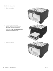
Jam in the fuser area 1. CAUTION: Wait until the fuser area has cooled before resuming printing. NOTE: If the sheet tears, remove all fragments before clearing the jam. 3. Remove any jammed sheets. Close the rear door. 130 Chapter 10 Solve problems ENWW Open the rear door. 2.
Jam in the fuser area 1. CAUTION: Wait until the fuser area has cooled before resuming printing. NOTE: If the sheet tears, remove all fragments before clearing the jam. 3. Remove any jammed sheets. Close the rear door. 130 Chapter 10 Solve problems ENWW Open the rear door. 2.
HP LaserJet Pro CP1520 - User Guide
Page 196
...4 fuser errors 118 jams, clearing 130 G graph paper, printing 11 grayscale printing (Windows) 67 H help printing options (Windows) 55 Help tab, HP ToolboxFX 89 HP Customer Care 160 HP Easy Color disabling 82 using 82 HP Embedded Web Server accessing 94 HP Embedded Web server 28 HP fraud hotline 99 HP Toolbox ...FX Status tab 89 HP ToolboxFX about 88 density settings 91 Help tab 89 ...
...4 fuser errors 118 jams, clearing 130 G graph paper, printing 11 grayscale printing (Windows) 67 H help printing options (Windows) 55 Help tab, HP ToolboxFX 89 HP Customer Care 160 HP Easy Color disabling 82 using 82 HP Embedded Web Server accessing 94 HP Embedded Web server 28 HP fraud hotline 99 HP Toolbox ...FX Status tab 89 HP ToolboxFX about 88 density settings 91 Help tab 89 ...

Service Manual
Page 7
... 19 Rear-side cover 21 Rear-upper cover 22 Rear door and rear-lower cover 23 Top cover ...25 Internal assemblies ...27 Main motor ...27 Fuser motor ...29 Intermediate transfer belt (ITB 30 Reinstall the ITB 35 DC controller PCA 37 Special consideration 37 ENWW v
... 19 Rear-side cover 21 Rear-upper cover 22 Rear door and rear-lower cover 23 Top cover ...25 Internal assemblies ...27 Main motor ...27 Fuser motor ...29 Intermediate transfer belt (ITB 30 Reinstall the ITB 35 DC controller PCA 37 Special consideration 37 ENWW v

Service Manual
Page 8
...Fuser ...56 2 Solve problems ...59 Solve problems checklist ...60 Menu map ...61 Troubleshooting process ...62 Pre-troubleshooting checklist 62 Power-on checks ...64 Tools for troubleshooting ...65 Diagrams ...65 Plug/jack locations 65 Locations of major components 66 General timing charts 68 General circuit diagram 69 Use HP ToolboxFX ...70 View the HP Color LaserJet... CP1520 Series Toolbox 70 HP ToolboxFX sections 71 Status 71 Event log 71 Help 71 System ...
...Fuser ...56 2 Solve problems ...59 Solve problems checklist ...60 Menu map ...61 Troubleshooting process ...62 Pre-troubleshooting checklist 62 Power-on checks ...64 Tools for troubleshooting ...65 Diagrams ...65 Plug/jack locations 65 Locations of major components 66 General timing charts 68 General circuit diagram 69 Use HP ToolboxFX ...70 View the HP Color LaserJet... CP1520 Series Toolbox 70 HP ToolboxFX sections 71 Status 71 Event log 71 Help 71 System ...
Service Manual
Page 9
... ...96 Jam in Tray 1 ...97 Jam in Tray 2 ...99 Jam in the fuser area 100 Jam in the output bin 101 Solve image quality problems ...102 Use the correct paper type setting in the printer driver 102 Change the paper type setting for Windows 102 Change the paper type setting... for Mac 102 Adjust color settings in the printer driver 103 Change the color theme for a print job 103 Change the color options 103 Use paper that meets HP specifications 104 Print a cleaning page ...105 Calibrate the product to align the...
... ...96 Jam in Tray 1 ...97 Jam in Tray 2 ...99 Jam in the fuser area 100 Jam in the output bin 101 Solve image quality problems ...102 Use the correct paper type setting in the printer driver 102 Change the paper type setting for Windows 102 Change the paper type setting... for Mac 102 Adjust color settings in the printer driver 103 Change the color theme for a print job 103 Change the color options 103 Use paper that meets HP specifications 104 Print a cleaning page ...105 Calibrate the product to align the...

Service Manual
Page 16
... cover (3 of 4) ...26 Remove the top cover (4 of 4) ...27 Remove the main motor (1 of 2 27 Remove the main motor (2 of 2 28 Remove the fuser motor (1 of 2 29 Remove the fuser motor (2 of 2 29 Remove the ITB (1 of 9) ...30 Remove the ITB (2 of 9) ...30 Remove the ITB (3 of 9) ...31 Remove the ITB (4 of...
... cover (3 of 4) ...26 Remove the top cover (4 of 4) ...27 Remove the main motor (1 of 2 27 Remove the main motor (2 of 2 28 Remove the fuser motor (1 of 2 29 Remove the fuser motor (2 of 2 29 Remove the ITB (1 of 9) ...30 Remove the ITB (2 of 9) ...30 Remove the ITB (3 of 9) ...31 Remove the ITB (4 of...

Service Manual
Page 17
... 1-82 Remove the power supply (fuser; 3 of 5 54 Figure 1-83 Remove the power supply (fuser; 4 of 5 54 Figure 1-84 Remove the power supply (fuser; 5 of 5 55 Figure 1-85 Remove the fuser (1 of 4) ...56 Figure 1-86 Remove the fuser (2 of 4) ...57 Figure 1-87 Remove the fuser (3 of 4) ...57 Figure 1-88 Remove the fuser (4 of 4) ...58 Figure 2-1 Major components...
... 1-82 Remove the power supply (fuser; 3 of 5 54 Figure 1-83 Remove the power supply (fuser; 4 of 5 54 Figure 1-84 Remove the power supply (fuser; 5 of 5 55 Figure 1-85 Remove the fuser (1 of 4) ...56 Figure 1-86 Remove the fuser (2 of 4) ...57 Figure 1-87 Remove the fuser (3 of 4) ...57 Figure 1-88 Remove the fuser (4 of 4) ...58 Figure 2-1 Major components...
Service Manual
Page 22
... Front door and Tray 1 door Control-panel module Rear-side cover Rear-upper cover Rear door and rear-lower cover Top cover Main motor Fuser motor Intermediate transfer belt DC controller PCA Formatter PCA Wireless PCA Power supply (high-voltage) Power supply (low-voltage) Remove Cartridge drawer Tray ...cover Remove Left cover Left cover Left cover Left cover Left cover Control-panel module Left cover Left cover Power supply (fuser) Right cover Left cover Fuser Right cover Left cover Remove Rear-side cover Rear-side cover Control panel module Rear-side cover Control panel module Rear...
... Front door and Tray 1 door Control-panel module Rear-side cover Rear-upper cover Rear door and rear-lower cover Top cover Main motor Fuser motor Intermediate transfer belt DC controller PCA Formatter PCA Wireless PCA Power supply (high-voltage) Power supply (low-voltage) Remove Cartridge drawer Tray ...cover Remove Left cover Left cover Left cover Left cover Left cover Control-panel module Left cover Left cover Power supply (fuser) Right cover Left cover Fuser Right cover Left cover Remove Rear-side cover Rear-side cover Control panel module Rear-side cover Control panel module Rear...
Service Manual
Page 47
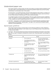
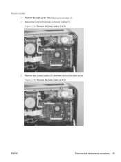
Figure 1-45 Remove the fuser motor (2 of 2) 1 3. Remove two screws (callout 2), and then remove the fuser motor. Disconnect one wire-harness connector (callout 1). Figure 1-44 Remove the fuser motor (1 of 2) 2 ENWW Removal and replacement procedures 29 Fuser motor 1. See Right cover on page 10. 2. Remove the right cover.
Figure 1-45 Remove the fuser motor (2 of 2) 1 3. Remove two screws (callout 2), and then remove the fuser motor. Disconnect one wire-harness connector (callout 1). Figure 1-44 Remove the fuser motor (1 of 2) 2 ENWW Removal and replacement procedures 29 Fuser motor 1. See Right cover on page 10. 2. Remove the right cover.

Service Manual
Page 64
7. Figure 1-68 Remove the power supply (high-voltage; 6 of 6) Reinstall the power supply (high voltage) ● Make sure that the power supply is not correctly installed, the product will not function correctly and a fuser open error (50.7000) might appear in the event log. Remove the power supply. Figure 1-69 Reinstall the power supply (high voltage) 1 46 Chapter 1 Removal and replacement ENWW If the power supply is correctly positioned under the tabs (callout 1) located on the product chassis.
7. Figure 1-68 Remove the power supply (high-voltage; 6 of 6) Reinstall the power supply (high voltage) ● Make sure that the power supply is not correctly installed, the product will not function correctly and a fuser open error (50.7000) might appear in the event log. Remove the power supply. Figure 1-69 Reinstall the power supply (high voltage) 1 46 Chapter 1 Removal and replacement ENWW If the power supply is correctly positioned under the tabs (callout 1) located on the product chassis.

Service Manual
Page 71
... page 13. ● Rear-side cover. Disconnect three wire-harness connectors (callout 3). Remove the following components: ● Right cover. Figure 1-80 Remove the power supply (fuser; 1 of 5) 3 ENWW Removal and replacement procedures 53 See Right cover on page 23. 2. See Rear door and rear-lower cover on page 10. ● Left...
... page 13. ● Rear-side cover. Disconnect three wire-harness connectors (callout 3). Remove the following components: ● Right cover. Figure 1-80 Remove the power supply (fuser; 1 of 5) 3 ENWW Removal and replacement procedures 53 See Right cover on page 23. 2. See Rear door and rear-lower cover on page 10. ● Left...

Service Manual
Page 72
Release one tab (callout 4), slide the retainer toward the interface connectors to release it, and then separate the retainer from the chassis. Make sure that these screws are ground screws. Figure 1-83 Remove the power supply (fuser; 4 of 5) 4 5. 4. NOTE: The two screws near the power switch are placed in the correct positions when the power supply is reinstalled. Remove four screws (callout 5). Figure 1-82 Remove the power supply (fuser; 3 of 5) 5 5 54 Chapter 1 Removal and replacement ENWW
Release one tab (callout 4), slide the retainer toward the interface connectors to release it, and then separate the retainer from the chassis. Make sure that these screws are ground screws. Figure 1-83 Remove the power supply (fuser; 4 of 5) 4 5. 4. NOTE: The two screws near the power switch are placed in the correct positions when the power supply is reinstalled. Remove four screws (callout 5). Figure 1-82 Remove the power supply (fuser; 3 of 5) 5 5 54 Chapter 1 Removal and replacement ENWW

Service Manual
Page 73
6. Figure 1-84 Remove the power supply (fuser; 5 of 5) ENWW Removal and replacement procedures 55 Remove the power supply.
6. Figure 1-84 Remove the power supply (fuser; 5 of 5) ENWW Removal and replacement procedures 55 Remove the power supply.

Service Manual
Page 74
See Control-panel module on page 10. ● Left cover. Figure 1-85 Remove the fuser (1 of 4) 2 1 56 Chapter 1 Removal and replacement ENWW Remove two screws (callout 1) and the power-supply cover (callout 2). See Right cover on page 19. ● Rear-.... See Rear-side cover on page 22. ● Rear door and rear-lower cover. See Rear-upper cover on page 21. ● Rear-upper cover. Fuser 1. See Top cover on page 25. 2.
See Control-panel module on page 10. ● Left cover. Figure 1-85 Remove the fuser (1 of 4) 2 1 56 Chapter 1 Removal and replacement ENWW Remove two screws (callout 1) and the power-supply cover (callout 2). See Right cover on page 19. ● Rear-.... See Rear-side cover on page 22. ● Rear door and rear-lower cover. See Rear-upper cover on page 21. ● Rear-upper cover. Fuser 1. See Top cover on page 25. 2.

Service Manual
Page 75
Remove four screws (callout 4). Figure 1-86 Remove the fuser (2 of 4) 4 ENWW Removal and replacement procedures 57 Figure 1-87 Remove the fuser (3 of 4) 3 3 4. Remove the wire harness from the guides and one retainer. 3. Disconnect five wire-harness connectors (callout 3).
Remove four screws (callout 4). Figure 1-86 Remove the fuser (2 of 4) 4 ENWW Removal and replacement procedures 57 Figure 1-87 Remove the fuser (3 of 4) 3 3 4. Remove the wire harness from the guides and one retainer. 3. Disconnect five wire-harness connectors (callout 3).


