Service Manual
Page 7
...105 Right lower cover 106 Left door and diverter 107 Left back cover 108 Back cover 109 Right and left rail covers 110 Top assemblies 111 Control panel 111 Laser/scanner assembly 112 Delivery assembly 113 Delivery-fan assembly 114 Delivery-assembly fans and face-down-bin fan (fans...-jam-removal knob 123 Registration-jam-removal knob 124 Right assemblies 125 Tray 1 125 Paper-input unit (PIU 126 Registration assembly 129 Transfer-guide assembly 131 Left assemblies 133 Duplexer 133 Fuser assembly 134 Back assemblies 135 Formatter 135 Low-voltage power supply 136 High-voltage ...
...105 Right lower cover 106 Left door and diverter 107 Left back cover 108 Back cover 109 Right and left rail covers 110 Top assemblies 111 Control panel 111 Laser/scanner assembly 112 Delivery assembly 113 Delivery-fan assembly 114 Delivery-assembly fans and face-down-bin fan (fans...-jam-removal knob 123 Registration-jam-removal knob 124 Right assemblies 125 Tray 1 125 Paper-input unit (PIU 126 Registration assembly 129 Transfer-guide assembly 131 Left assemblies 133 Duplexer 133 Fuser assembly 134 Back assemblies 135 Formatter 135 Low-voltage power supply 136 High-voltage ...
Service Manual
Page 9
... LAN troubleshooting (HP LaserJet 9040n/9050n, HP LaserJet 9040dn/9050dn, HP LaserJet 9050mfp, and HP LaserJet 9040mfp only 247 Wiring diagrams 251 8 Parts and diagrams Introduction 256 Ordering parts 256 Consumables, supplies, accessories, FRUs, and documentation 257 Common hardware 261 Illustrations and parts lists 262 External covers and panels 262 Left door and diverter 264 Right cover assembly 265 Internal...
... LAN troubleshooting (HP LaserJet 9040n/9050n, HP LaserJet 9040dn/9050dn, HP LaserJet 9050mfp, and HP LaserJet 9040mfp only 247 Wiring diagrams 251 8 Parts and diagrams Introduction 256 Ordering parts 256 Consumables, supplies, accessories, FRUs, and documentation 257 Common hardware 261 Illustrations and parts lists 262 External covers and panels 262 Left door and diverter 264 Right cover assembly 265 Internal...
Service Manual
Page 11
...specifications 9 Table 10. DIP switch settings 223 Table 25. Transfer roller assembly 280 Table 47. Features of the HP LaserJet 9040/9050 Series printers 4 Table 3. Features of the HP LaserJet 9000 Series printers 2 Table 2. Failure sequence of 4 269 Table 38.... (HP LaserJet 9000 7 Table 6. Electrical specifications (HP LaserJet 9040 8 Table 7. Alphabetic error messages 180 Table 21. Left door and diverter 264 Table 35. Service menu 215 Table 24. Physical specifications 7 Table 5. Service test abnormality codes 213 Table 23. Delivery assembly 282...
...specifications 9 Table 10. DIP switch settings 223 Table 25. Transfer roller assembly 280 Table 47. Features of the HP LaserJet 9040/9050 Series printers 4 Table 3. Features of the HP LaserJet 9000 Series printers 2 Table 2. Failure sequence of 4 269 Table 38.... (HP LaserJet 9000 7 Table 6. Electrical specifications (HP LaserJet 9040 8 Table 7. Alphabetic error messages 180 Table 21. Left door and diverter 264 Table 35. Service menu 215 Table 24. Physical specifications 7 Table 5. Service test abnormality codes 213 Table 23. Delivery assembly 282...
Service Manual
Page 15
... Figure 115. Repeating defect ruler 243 Figure 131. Printer wiring diagram (HP LaserJet 9000 series printer 251 Figure 132. Printer wiring diagram (HP LaserJet 9040/9050 series printer) . . 252 Figure 133. Cartridge lifter assembly 276 Figure 144. 500-sheet trays (tray 2 and tray 3 277... 128. Left door and diverter 264 Figure 136. Internal components (2 of 4 268 Figure 139. Sample configuration page 227 Figure 125. Fuser delivery drive assembly 275 Figure 143. Figure 108. Drive assembly 158 Figure 110. Sample event log (HP LaserJet 9000 series printer page shown)...
... Figure 115. Repeating defect ruler 243 Figure 131. Printer wiring diagram (HP LaserJet 9000 series printer 251 Figure 132. Printer wiring diagram (HP LaserJet 9040/9050 series printer) . . 252 Figure 133. Cartridge lifter assembly 276 Figure 144. 500-sheet trays (tray 2 and tray 3 277... 128. Left door and diverter 264 Figure 136. Internal components (2 of 4 268 Figure 139. Sample configuration page 227 Figure 125. Fuser delivery drive assembly 275 Figure 143. Figure 108. Drive assembly 158 Figure 110. Sample event log (HP LaserJet 9000 series printer page shown)...
Service Manual
Page 113
...105 Right lower cover 106 Left door and diverter 107 Left back cover 108 Back cover 109 Right and left rail covers 110 Top assemblies 111 Control panel 111 Laser/scanner assembly 112 Delivery assembly 113 Delivery-fan assembly 114 Delivery-assembly fans and face-down-bin fan (fans...-jam-removal knob 123 Registration-jam-removal knob 124 Right assemblies 125 Tray 1 125 Paper-input unit (PIU 126 Registration assembly 129 Transfer-guide assembly 131 Left assemblies 133 Duplexer 133 Fuser assembly 134 Back assemblies 135 Formatter 135 Low-voltage power supply 136 High-voltage ...
...105 Right lower cover 106 Left door and diverter 107 Left back cover 108 Back cover 109 Right and left rail covers 110 Top assemblies 111 Control panel 111 Laser/scanner assembly 112 Delivery assembly 113 Delivery-fan assembly 114 Delivery-assembly fans and face-down-bin fan (fans...-jam-removal knob 123 Registration-jam-removal knob 124 Right assemblies 125 Tray 1 125 Paper-input unit (PIU 126 Registration assembly 129 Transfer-guide assembly 131 Left assemblies 133 Duplexer 133 Fuser assembly 134 Back assemblies 135 Formatter 135 Low-voltage power supply 136 High-voltage ...
Service Manual
Page 209
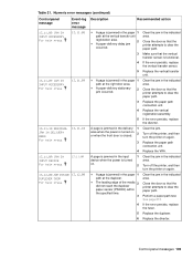
... transfer sensor is closed. 2 3 4 Clear the jam. Perform a paper-path test. Replace the paper path connection unit. Replace the diverter. Replace the vertical registration assembly. Control-panel messages 193 Make sure that the printer attempts to clear the paper path. Replace the VRA. 13.11.0A JAM IN... power is turned on . 2 z A page is jammed in the paper 1 path at the right door area. If the error persists, replace the diverter. 13.11.10 RESIDUAL JAM IN DELIVERY AREA For help press 13.11.08 13.11.09 z A page is jammed in the paper 1 path at...
... transfer sensor is closed. 2 3 4 Clear the jam. Perform a paper-path test. Replace the paper path connection unit. Replace the diverter. Replace the vertical registration assembly. Control-panel messages 193 Make sure that the printer attempts to clear the paper path. Replace the VRA. 13.11.0A JAM IN... power is turned on . 2 z A page is jammed in the paper 1 path at the right door area. If the error persists, replace the diverter. 13.11.10 RESIDUAL JAM IN DELIVERY AREA For help press 13.11.08 13.11.09 z A page is jammed in the paper 1 path at...
Service Manual
Page 210
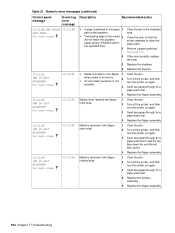
... the flipper assembly. 194 Chapter 7 Troubleshooting Turn off the printer, and then turn the printer on . 2 z An auto-flush operation is turned on again. Send two pages through for a paper-path test. Replace the diverter. Table 21. Close the door so that the printer attempts to test the top face...-down bin and the left face-up bin. 4 Replace the flipper assembly. 13.12.04 JAM IN LEFT ACCESSORY For help press 13.12...
... the flipper assembly. 194 Chapter 7 Troubleshooting Turn off the printer, and then turn the printer on . 2 z An auto-flush operation is turned on again. Send two pages through for a paper-path test. Replace the diverter. Table 21. Close the door so that the printer attempts to test the top face...-down bin and the left face-up bin. 4 Replace the flipper assembly. 13.12.04 JAM IN LEFT ACCESSORY For help press 13.12...
Service Manual
Page 271
... and panels 262 Left door and diverter 264 Right cover assembly 265 Internal 266 Internal components 266 Drum feed drive assembly 274 Fuser delivery drive assembly 275 Cartridge lifter assembly 276 500-sheet trays (tray 2 and tray 3 277 Paper input unit 278 Registration assembly 279 Transfer roller assembly 280 Delivery assembly 281 PCA assembly location 283 Tray 4 284 Tray...
... and panels 262 Left door and diverter 264 Right cover assembly 265 Internal 266 Internal components 266 Drum feed drive assembly 274 Fuser delivery drive assembly 275 Cartridge lifter assembly 276 500-sheet trays (tray 2 and tray 3 277 Paper input unit 278 Registration assembly 279 Transfer roller assembly 280 Delivery assembly 281 PCA assembly location 283 Tray 4 284 Tray...
Service Manual
Page 308
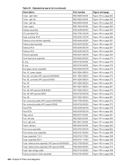
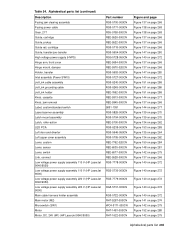
... Deck controller PCA Delivery cross member assembly Delivery feed assembly Delivery PCA Delivery PCA Diverter assembly Drum feed drive assembly E ring E ring End paper sensor assembly Fan, #1, power supply Fan, #2, controller (HP LaserJet 9040/9050) Fan, #2, controller (HP LaserJet 9000) Fan, #3 Fan, #4 Fan, #5 (HP LaserJet 9040/9050) Fan, #5 (HP LaserJet 9000) Fan, #6 Fan connecting cable (HP LaserJet 9040/9050) Fan connecting cable (HP LaserJet 9000) Feed PCA Feed PCA Flag, sensor...
... Deck controller PCA Delivery cross member assembly Delivery feed assembly Delivery PCA Delivery PCA Diverter assembly Drum feed drive assembly E ring E ring End paper sensor assembly Fan, #1, power supply Fan, #2, controller (HP LaserJet 9040/9050) Fan, #2, controller (HP LaserJet 9000) Fan, #3 Fan, #4 Fan, #5 (HP LaserJet 9040/9050) Fan, #5 (HP LaserJet 9000) Fan, #6 Fan connecting cable (HP LaserJet 9040/9050) Fan connecting cable (HP LaserJet 9000) Feed PCA Feed PCA Flag, sensor...
Service Manual
Page 309
...-action LED PCA Left door and diverter Left upper cover assembly Lever, custom Lever, sensor Lever, switch Link, connect Low voltage power supply assembly 110 V (HP LaserJet 9040/9050) Low voltage power supply assembly 110 V (HP LaserJet 9000) Low voltage power supply assembly 220 V (HP LaserJet 9040/9050) Low voltage power supply assembly 220 V (HP LaserJet 9000) Main cable harness holder assembly Main motor (M2) Microswitch (SW1...
...-action LED PCA Left door and diverter Left upper cover assembly Lever, custom Lever, sensor Lever, switch Link, connect Low voltage power supply assembly 110 V (HP LaserJet 9040/9050) Low voltage power supply assembly 110 V (HP LaserJet 9000) Low voltage power supply assembly 220 V (HP LaserJet 9040/9050) Low voltage power supply assembly 220 V (HP LaserJet 9000) Main cable harness holder assembly Main motor (M2) Microswitch (SW1...
Service Manual
Page 313
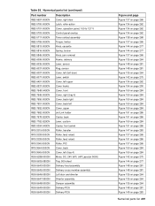
...-action RB2-5701-000CN Cover, operation panel, 100 to 127 V RB2-5703-000CN Control panel overlay RB2-5717-000CN Toner contact assembly RB2-5759-000CN Torque, limiter RB2-5813-000CN Knob, cassette RB2-5816-000CN Spring, torsion RB2-5845-000CN Knob, jam removal RB2...-5288-000CN Motor, DC, 24V (M1) (HP LaserJet 9000) RG5-5635-080CN Tray, 500-sheet RG5-5643-030CN Delivery feed assembly RG5-5645-000CN Delivery cross member assembly RG5-5646-050CN Left door and diverter RG5-5647-050CN Diverter assembly RG5-5648-000CN Damper assembly RG5-5649-000CN Delivery PCA RG5-5649-000CN Delivery...
...-action RB2-5701-000CN Cover, operation panel, 100 to 127 V RB2-5703-000CN Control panel overlay RB2-5717-000CN Toner contact assembly RB2-5759-000CN Torque, limiter RB2-5813-000CN Knob, cassette RB2-5816-000CN Spring, torsion RB2-5845-000CN Knob, jam removal RB2...-5288-000CN Motor, DC, 24V (M1) (HP LaserJet 9000) RG5-5635-080CN Tray, 500-sheet RG5-5643-030CN Delivery feed assembly RG5-5645-000CN Delivery cross member assembly RG5-5646-050CN Left door and diverter RG5-5647-050CN Diverter assembly RG5-5648-000CN Damper assembly RG5-5649-000CN Delivery PCA RG5-5649-000CN Delivery...
Service Manual
Page 319
...238 diverter, left 107, 264 right 105 DOS prompt, communications test 246 dots per inch (dpi) features 2, 4 settings 44 dots, vertical 242 double-sided printing 42 Down arrow, control panel 31 dpi (dots per inch) features 2, 4 settings 44 draft printing 45, 68 drive assembly (... 157 drivers, changing settings from 36 dropouts, troubleshooting 238 drum bias generation 79 cleaning process, image formation operations 85 feed drive assembly, diagrams and part numbers 274 ground path, troubleshooting 239 image defects, troubleshooting 234 image formation operations 84 rotation check 220 drum motor...
...238 diverter, left 107, 264 right 105 DOS prompt, communications test 246 dots per inch (dpi) features 2, 4 settings 44 dots, vertical 242 double-sided printing 42 Down arrow, control panel 31 dpi (dots per inch) features 2, 4 settings 44 draft printing 45, 68 drive assembly (... 157 drivers, changing settings from 36 dropouts, troubleshooting 238 drum bias generation 79 cleaning process, image formation operations 85 feed drive assembly, diagrams and part numbers 274 ground path, troubleshooting 239 image defects, troubleshooting 234 image formation operations 84 rotation check 220 drum motor...


