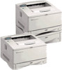
HP LaserJet 5000, 5000 N, 5000 GN, and 5000 DN Printers - User Guide
Page 186
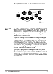
... manner. E-4 Regulatory Information EN The diagram below represents how HP LaserJet toner cartridges are recovered, tested, and reused as fully-warrantied service parts. Many of the functional parts are recycled, if possible. Europe Only: Design for them. Many of the functional parts are recycled: Printer and Parts U.S. The number of the product parts are recovered, tested, and reused...
... manner. E-4 Regulatory Information EN The diagram below represents how HP LaserJet toner cartridges are recovered, tested, and reused as fully-warrantied service parts. Many of the functional parts are recycled, if possible. Europe Only: Design for them. Many of the functional parts are recycled: Printer and Parts U.S. The number of the product parts are recovered, tested, and reused...
Service Manual
Page 8
... Quality 7-49 Interface Troubleshooting 7-77 Reference Diagrams 7-80 Locations of Components 7-80 Sensors and Signals 7-88 DC Controller PCA Inputs and Outputs 7-107 8 Parts and Diagrams Overview 8-1 How To Use the Parts Lists and Diagrams 8-2 Accessories and Supplies 8-4 Common Hardware and Replacement Cables 8-6 Illustrations and Parts Lists 8-7 Alphabetical Parts List 8-39 Numerical Parts List 8-44 Index EN Contents 5
... Quality 7-49 Interface Troubleshooting 7-77 Reference Diagrams 7-80 Locations of Components 7-80 Sensors and Signals 7-88 DC Controller PCA Inputs and Outputs 7-107 8 Parts and Diagrams Overview 8-1 How To Use the Parts Lists and Diagrams 8-2 Accessories and Supplies 8-4 Common Hardware and Replacement Cables 8-6 Illustrations and Parts Lists 8-7 Alphabetical Parts List 8-39 Numerical Parts List 8-44 Index EN Contents 5

Service Manual
Page 332
8 Parts and Diagrams Overview The figures in this chapter identify and locate the printer's major subassemblies and replacement parts. This chapter discusses the following: q How to Use the Parts Lists and Diagrams q Accessories and Supplies q Illustrations and Parts Lists EN Overview 8-1
8 Parts and Diagrams Overview The figures in this chapter identify and locate the printer's major subassemblies and replacement parts. This chapter discusses the following: q How to Use the Parts Lists and Diagrams q Accessories and Supplies q Illustrations and Parts Lists EN Overview 8-1
Service Manual
Page 333
...exploded view diagram. All standard part numbers listed are stocked and may be ordered from HP's Support Materials Organization (SMO), or Support Materials Europe (SME). Support Materials Organization 8050 Foothills Blvd. Each table lists the item number for the replaceable part, the associated part number for...1-800-387-3154 (Toronto) 516-671-8383 United Kingdom: 0734-441212 Germany: 0130-3322 8-2 Parts and Diagrams EN How To Use the Parts Lists and Diagrams Note The figures in this chapter illustrate the major subassemblies in the description column to the voltage ...
...exploded view diagram. All standard part numbers listed are stocked and may be ordered from HP's Support Materials Organization (SMO), or Support Materials Europe (SME). Support Materials Organization 8050 Foothills Blvd. Each table lists the item number for the replaceable part, the associated part number for...1-800-387-3154 (Toronto) 516-671-8383 United Kingdom: 0734-441212 Germany: 0130-3322 8-2 Parts and Diagrams EN How To Use the Parts Lists and Diagrams Note The figures in this chapter illustrate the major subassemblies in the description column to the voltage ...
Service Manual
Page 334
Note Contact your local HP Parts Coordinator for other local phone numbers. EN How To Use the Parts Lists and Diagrams 8-3 Parts that have no item number or part number listed are not field replacement parts and cannot be ordered.
Note Contact your local HP Parts Coordinator for other local phone numbers. EN How To Use the Parts Lists and Diagrams 8-3 Parts that have no item number or part number listed are not field replacement parts and cannot be ordered.
Service Manual
Page 335
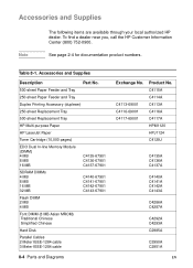
... product numbers. Accessories and Supplies Description Part No. 500-sheet Paper Feeder and Tray 250-sheet Paper Feeder and Tray Duplex Printing Accessory (duplexer) 250-sheet Replacement Tray 500-sheet Replacement Tray HP Multi-purpose Paper HP LaserJet Paper Toner Cartridge (10,000 pages... Asian MROM) Traditional Chinese Simplified Chinese Hard Disk Parallel Cables 2 Meter IEEE-1284 cable 3 Meter IEEE-1284 cable 8-4 Parts and Diagrams Exchange No. C4113-69001 C4116-69001 C4117-69001 Product No. C4115A C4114A C4113A C4116A C4117A HPM1120 HPJ1124 C4129J C4135A C4136A C4137A...
... product numbers. Accessories and Supplies Description Part No. 500-sheet Paper Feeder and Tray 250-sheet Paper Feeder and Tray Duplex Printing Accessory (duplexer) 250-sheet Replacement Tray 500-sheet Replacement Tray HP Multi-purpose Paper HP LaserJet Paper Toner Cartridge (10,000 pages... Asian MROM) Traditional Chinese Simplified Chinese Hard Disk Parallel Cables 2 Meter IEEE-1284 cable 3 Meter IEEE-1284 cable 8-4 Parts and Diagrams Exchange No. C4113-69001 C4116-69001 C4117-69001 Product No. C4115A C4114A C4113A C4116A C4117A HPM1120 HPJ1124 C4129J C4135A C4136A C4137A...
Service Manual
Page 337
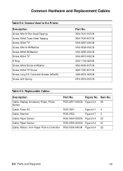
...-000CN Figure 8-4 26 RG5-3561 Figure 8-7 4 RG5-3562 Figure 8-7 3 RG5-3554-000CN Figure 8-4 20 RG5-3558-000CN Figure 8-4 21 RH2-5338-000CN Figure 8-4 22 8-6 Parts and Diagrams EN Figure No. Common Hardware and Replacement Cables Table 8-2. Replaceable Cables Description Cable, Display, Accessory Power, Photo Sensor Cable, Fuser AC Cable, Scanner Cable, Paper...
...-000CN Figure 8-4 26 RG5-3561 Figure 8-7 4 RG5-3562 Figure 8-7 3 RG5-3554-000CN Figure 8-4 20 RG5-3558-000CN Figure 8-4 21 RH2-5338-000CN Figure 8-4 22 8-6 Parts and Diagrams EN Figure No. Common Hardware and Replacement Cables Table 8-2. Replaceable Cables Description Cable, Display, Accessory Power, Photo Sensor Cable, Fuser AC Cable, Scanner Cable, Paper...
Service Manual
Page 339
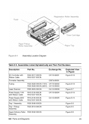
Assemblies Listed Alphabetically and Their Part Numbers Description Part No. Exchange No. DC Controller with Ribbon Cable RG5-3517-000CN RH2-5337-000CN C4110-69001 Formatter Assembly C3974-69001 Fusing RG5-3528-000CN (110V) ...-3519-000CN Upper Delivery Roller RG5-3542-000CN Assembly Exploded View in Figure Figure 8-16 Figure 8-18 Figure 8-7 Figure 8-16 Figure 8-16 Figure 8-2 Figure 8-5 Figure 8-8 8-8 Parts and Diagrams EN Fuser Registration Roller Assembly Paper Pickup Roller Assembly Toner Cartridge Paper Tray Figure 8-1 Assembly Location...
Assemblies Listed Alphabetically and Their Part Numbers Description Part No. Exchange No. DC Controller with Ribbon Cable RG5-3517-000CN RH2-5337-000CN C4110-69001 Formatter Assembly C3974-69001 Fusing RG5-3528-000CN (110V) ...-3519-000CN Upper Delivery Roller RG5-3542-000CN Assembly Exploded View in Figure Figure 8-16 Figure 8-18 Figure 8-7 Figure 8-16 Figure 8-16 Figure 8-2 Figure 8-5 Figure 8-8 8-8 Parts and Diagrams EN Fuser Registration Roller Assembly Paper Pickup Roller Assembly Toner Cartridge Paper Tray Figure 8-1 Assembly Location...
Service Manual
Page 341
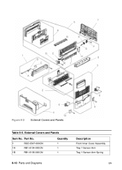
External Covers and Panels Item No. Part No. 1 RG5-3547-000CN 1A RB1-6134-000CN 1B RB1-6136-000CN Quantity 1 1 1 Description Front Inner Cover Assembly Tray 1 Sensor Arm Tray 1 Sensor Arm Spring 8-10 Parts and Diagrams EN 7 5 A B E GC 1 B C F D H 8 I 3 A 2 Figure 8-2 6 4 10 External Covers and Panels 6 9 Table 8-5.
External Covers and Panels Item No. Part No. 1 RG5-3547-000CN 1A RB1-6134-000CN 1B RB1-6136-000CN Quantity 1 1 1 Description Front Inner Cover Assembly Tray 1 Sensor Arm Tray 1 Sensor Arm Spring 8-10 Parts and Diagrams EN 7 5 A B E GC 1 B C F D H 8 I 3 A 2 Figure 8-2 6 4 10 External Covers and Panels 6 9 Table 8-5.
Service Manual
Page 345
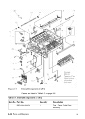
20 10 11 1 18 12 6 7 13 2 3 9 8 19 26 17 5 15 24 Figure 8-4 22 4 23 21 16 14 25 Internal Components (1 of 4) Item No. Part No. 1 RG5-3520-000CN Quantity 1 Description Tray 1 Paper Guide Plate Assembly 8-14 Parts and Diagrams EN Table 8-7. Internal Components (1 of 4) Screws: M4x10, Tapping, Pan Head unless otherwise indicated Cables are listed in Table 8-3 on page 8-6.
20 10 11 1 18 12 6 7 13 2 3 9 8 19 26 17 5 15 24 Figure 8-4 22 4 23 21 16 14 25 Internal Components (1 of 4) Item No. Part No. 1 RG5-3520-000CN Quantity 1 Description Tray 1 Paper Guide Plate Assembly 8-14 Parts and Diagrams EN Table 8-7. Internal Components (1 of 4) Screws: M4x10, Tapping, Pan Head unless otherwise indicated Cables are listed in Table 8-3 on page 8-6.

Service Manual
Page 347
17 22 24 20 18 19 25 23 24 9 8 7 1 11 13 12 12 13 21 10 15 16 14 2 3 1 4 6 5 Screws M4x10, Tapping, Pan Head unless otherwise noted Figure 8-5 Internal Components (2 of 4) 8-16 Parts and Diagrams EN
17 22 24 20 18 19 25 23 24 9 8 7 1 11 13 12 12 13 21 10 15 16 14 2 3 1 4 6 5 Screws M4x10, Tapping, Pan Head unless otherwise noted Figure 8-5 Internal Components (2 of 4) 8-16 Parts and Diagrams EN
Service Manual
Page 355
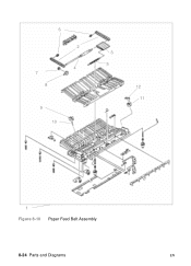
6 2 4 7 8 9 10 3 5 12 11 1 Figure 8-10 Paper Feed Belt Assembly 8-24 Parts and Diagrams EN
6 2 4 7 8 9 10 3 5 12 11 1 Figure 8-10 Paper Feed Belt Assembly 8-24 Parts and Diagrams EN
Service Manual
Page 357
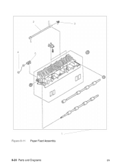
2 3 4 5 1 Figure 8-11 Paper Feed Assembly 8-26 Parts and Diagrams EN
2 3 4 5 1 Figure 8-11 Paper Feed Assembly 8-26 Parts and Diagrams EN
Service Manual
Page 363
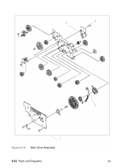
3 4 1 Figure 8-14 Main Drive Assembly 8-32 Parts and Diagrams 2 EN
3 4 1 Figure 8-14 Main Drive Assembly 8-32 Parts and Diagrams 2 EN
Service Manual
Page 365
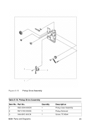
3 2 1 Figure 8-15 Pickup Drive Assembly Table 8-18. Pickup Drive Assembly Item No. Part No. 1 RG5-3544-000CN 2 RH7-5193-000CN 3 XA9-0815-000CN Quantity 1 1 1 Description Pickup Gear Assembly Pickup Solenoid Screw, TP, M3x4 8-34 Parts and Diagrams EN
3 2 1 Figure 8-15 Pickup Drive Assembly Table 8-18. Pickup Drive Assembly Item No. Part No. 1 RG5-3544-000CN 2 RH7-5193-000CN 3 XA9-0815-000CN Quantity 1 1 1 Description Pickup Gear Assembly Pickup Solenoid Screw, TP, M3x4 8-34 Parts and Diagrams EN
Service Manual
Page 367
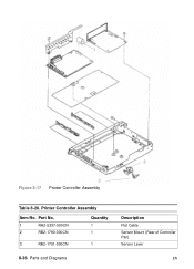
Printer Controller Assembly Item No. Part No. 1 RH2-5337-000CN 2 RB2-1790-000CN Quantity 1 1 3 RB2-1791-000CN 1 8-36 Parts and Diagrams Description Flat Cable Sensor Mount (Rear of Controller Pan) Sensor Lever EN 1 2 Figure 8-17 3 Printer Controller Assembly Table 8-20.
Printer Controller Assembly Item No. Part No. 1 RH2-5337-000CN 2 RB2-1790-000CN Quantity 1 1 3 RB2-1791-000CN 1 8-36 Parts and Diagrams Description Flat Cable Sensor Mount (Rear of Controller Pan) Sensor Lever EN 1 2 Figure 8-17 3 Printer Controller Assembly Table 8-20.
Service Manual
Page 373
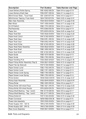
Alphabetical Parts List Description 250-sheet Universal Paper Tray Cable (Fuser AC) Cable (Scanner) Cable, Display, Accessory Power, Photo Sensor Cable, Paper Sensor Cable, Paper Sensor...Cover Face Down Bin Full Sensor Lever Face Down Guide Roller Face Up Deflector Face Up Tray Assembly Fan Feed Roller, 500-sheet Feeder Part Number C4116A RG5-3561-000CN RG5-3562-000CN RG5-3557-000CN RG5-3554-000CN RG5-3558-000CN RH2-5338-000CN RB2-1796-000CN RB2-... 8-22 Table 8-9 on page 8-19 Table 8-5 on page 8-10 Table 8-5 on page 8-10 Table 8-8 on page 8-17 Table 8-23 on page 8-41 8-42 Parts and Diagrams EN
Alphabetical Parts List Description 250-sheet Universal Paper Tray Cable (Fuser AC) Cable (Scanner) Cable, Display, Accessory Power, Photo Sensor Cable, Paper Sensor Cable, Paper Sensor...Cover Face Down Bin Full Sensor Lever Face Down Guide Roller Face Up Deflector Face Up Tray Assembly Fan Feed Roller, 500-sheet Feeder Part Number C4116A RG5-3561-000CN RG5-3562-000CN RG5-3557-000CN RG5-3554-000CN RG5-3558-000CN RH2-5338-000CN RB2-1796-000CN RB2-... 8-22 Table 8-9 on page 8-19 Table 8-5 on page 8-10 Table 8-5 on page 8-10 Table 8-8 on page 8-17 Table 8-23 on page 8-41 8-42 Parts and Diagrams EN
Service Manual
Page 375
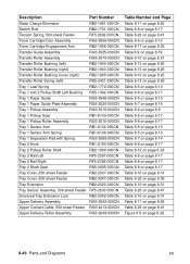
...-sheet Feeder Pickup Shaft Bushing - Tray 1 and 2 Pickup Solenoid Power Connector Power Inlet Assembly Power Supply (100 - 120 V) Power Supply (220 - 240 V) Rear Cover Assembly Part Number RB1-6252-000CN RS6-0357-000CN XB1-2300-607CN XB4-7300-807CN RG5-3543-000CN RH7-1356-000CN RB2-1744-000CN RF5-2399-000CN... page 8-34 Table 8-7 on page 8-14 Table 8-8 on page 8-17 Table 8-19 on page 8-35 Table 8-19 on page 8-35 Table 8-5 on page 8-10 8-44 Parts and Diagrams EN Tray 1 and 2 Pickup Shaft Bushing -
...-sheet Feeder Pickup Shaft Bushing - Tray 1 and 2 Pickup Solenoid Power Connector Power Inlet Assembly Power Supply (100 - 120 V) Power Supply (220 - 240 V) Rear Cover Assembly Part Number RB1-6252-000CN RS6-0357-000CN XB1-2300-607CN XB4-7300-807CN RG5-3543-000CN RH7-1356-000CN RB2-1744-000CN RF5-2399-000CN... page 8-34 Table 8-7 on page 8-14 Table 8-8 on page 8-17 Table 8-19 on page 8-35 Table 8-19 on page 8-35 Table 8-5 on page 8-10 8-44 Parts and Diagrams EN Tray 1 and 2 Pickup Shaft Bushing -
Service Manual
Page 377
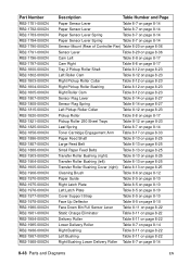
Description Part Number Static Charge Eliminator RB2-1981-000CN Switch Rod RB2-1731-000CN Tension Spring, 500-sheet Feeder RF5-2632-000CN Toner Cartridge Door Assembly RG5-... Table 8-23 on page 8-41 Table 8-16 on page 8-31 Table 8-11 on page 8-22 Table 8-23 on page 8-41 Figure 8-8 on page 8-22 8-46 Parts and Diagrams EN
Description Part Number Static Charge Eliminator RB2-1981-000CN Switch Rod RB2-1731-000CN Tension Spring, 500-sheet Feeder RF5-2632-000CN Toner Cartridge Door Assembly RG5-... Table 8-23 on page 8-41 Table 8-16 on page 8-31 Table 8-11 on page 8-22 Table 8-23 on page 8-41 Figure 8-8 on page 8-22 8-46 Parts and Diagrams EN
Service Manual
Page 379
Part Number RB2-1781-000CN RB2-1782-000CN RB2-1783-000CN RB2-1784-000CN RB2-1790-000CN RB2-1791-000CN RB2-1796-000CN RB2-1797-000CN ... 8-14 Right Bushing Table 8-11 on page 8-22 Left Bushing Table 8-11 on page 8-22 Right Bushing Lower Delivery Roller Table 8-7 on page 8-14 8-48 Parts and Diagrams EN
Part Number RB2-1781-000CN RB2-1782-000CN RB2-1783-000CN RB2-1784-000CN RB2-1790-000CN RB2-1791-000CN RB2-1796-000CN RB2-1797-000CN ... 8-14 Right Bushing Table 8-11 on page 8-22 Left Bushing Table 8-11 on page 8-22 Right Bushing Lower Delivery Roller Table 8-7 on page 8-14 8-48 Parts and Diagrams EN


