Packer Arm Installation
Page 1
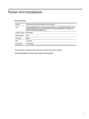
... Arm Installation Document details Purpose To describe how to install a new packer arm in this document. Document number CA393-00540 Revision number Rev03 Kit number Q5025C Date 17 July 2018 Security level HP Confidential The information contained in the rewinder Scope HP Indigo WS6000 Digital Press, HP Indigo WS6600 Digital Press, HP Indigo WS6800 Digital Press, HP Indigo 6900 Digital Press, HP Indigo 6r Digital Press, HP Indigo 8000 Digital Press, HP Indigo press ws4500, HP Indigo WS4600 Digital Press. Check CE Suitcase for the most recent version of this document is...
... Arm Installation Document details Purpose To describe how to install a new packer arm in this document. Document number CA393-00540 Revision number Rev03 Kit number Q5025C Date 17 July 2018 Security level HP Confidential The information contained in the rewinder Scope HP Indigo WS6000 Digital Press, HP Indigo WS6600 Digital Press, HP Indigo WS6800 Digital Press, HP Indigo 6900 Digital Press, HP Indigo 6r Digital Press, HP Indigo 8000 Digital Press, HP Indigo press ws4500, HP Indigo WS4600 Digital Press. Check CE Suitcase for the most recent version of this document is...
Packer Arm Installation
Page 29
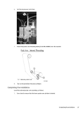
Completing the installation Level the external packer arm assembly, as follows: 1. Mount the packer arm threading label (p/n CA396-00880) onto the rewinder. 8. Completing the installation 27 6. Turn on the pressStart the press software. Use a level to 0.2 bars. 7. Set the air pressure to ensure that the lower packer arm cylinder is leveled.
Completing the installation Level the external packer arm assembly, as follows: 1. Mount the packer arm threading label (p/n CA396-00880) onto the rewinder. 8. Completing the installation 27 6. Turn on the pressStart the press software. Use a level to 0.2 bars. 7. Set the air pressure to ensure that the lower packer arm cylinder is leveled.
Packer Arm Installation
Page 32
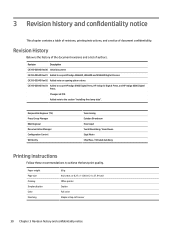
... (TS) Press Group Manager R&D Engineer Documentation Manager Configuration Control Written By Yossi Asaiag Esteban Birenbaum Erez Kopel Yuval Bloomberg / Isaac Diwan Sigal Aknin Chip Moss / Yehudah Goldberg Printing instructions Follow these recommendations to achieve the best print quality. Paper weight Page size Printing Simplex/duplex Color Finishing 80 g A4, Letter, or 8.27 x 11.00 in (21 x 27.94 cm) Office printer Duplex Full color Staple at...
... (TS) Press Group Manager R&D Engineer Documentation Manager Configuration Control Written By Yossi Asaiag Esteban Birenbaum Erez Kopel Yuval Bloomberg / Isaac Diwan Sigal Aknin Chip Moss / Yehudah Goldberg Printing instructions Follow these recommendations to achieve the best print quality. Paper weight Page size Printing Simplex/duplex Color Finishing 80 g A4, Letter, or 8.27 x 11.00 in (21 x 27.94 cm) Office printer Duplex Full color Staple at...
Rewinder Service
Page 1
Rewinder Service Document details Purpose To describe how to service the rewinder Scope HP Indigo WS6000 Digital Press, HP Indigo WS6600 Digital Press, HP Indigo WS6800 Digital Press, HP Indigo WS4500 Digital Press, HP Indigo WS4600 Digital Press. i Check CE Suitcase for the most recent version of release. Document number CA393-00580 Revision number Rev 04 Date 16 November 2021 Security level HP Confidential The information contained in this document is accurate at the date of this document.
Rewinder Service Document details Purpose To describe how to service the rewinder Scope HP Indigo WS6000 Digital Press, HP Indigo WS6600 Digital Press, HP Indigo WS6800 Digital Press, HP Indigo WS4500 Digital Press, HP Indigo WS4600 Digital Press. i Check CE Suitcase for the most recent version of release. Document number CA393-00580 Revision number Rev 04 Date 16 November 2021 Security level HP Confidential The information contained in this document is accurate at the date of this document.

Rewinder Service
Page 2
... tubes ...41 Installing the main tube ...41 Installing the clamp tube...42 Installing the short tube...47 Installing the engagement and disengagement tubes 49 Replacing the packer arm...54 Disassembling the packer arm...54 Disassembling the packer arm adjustable external assembly 55 Installing the new packer arm ...56 Aligning the packer arm...56 Replacing the web guide ...57 Old type of web guide...59 ii
... tubes ...41 Installing the main tube ...41 Installing the clamp tube...42 Installing the short tube...47 Installing the engagement and disengagement tubes 49 Replacing the packer arm...54 Disassembling the packer arm...54 Disassembling the packer arm adjustable external assembly 55 Installing the new packer arm ...56 Aligning the packer arm...56 Replacing the web guide ...57 Old type of web guide...59 ii
Rewinder Service
Page 3
... Printing instructions ...84 Confidentiality notice...85 iii Grease and oil types...80 Appendix 2- Replacing the old type of web guide ...59 Setup instructions ...60 Stage #1...60 Stage #2...61 Parameter declaration...62 Resetting the web guide ultrasonic sensor (new type 64 Replacing the drive shaft and the inflatable balloons (for the new type shaft p/n CU153-02574 64 Replacing the inflatable balloon for older shafts (p/n CU153-02583 73 Rewinder 12P controller...77 Adjusting...
... Printing instructions ...84 Confidentiality notice...85 iii Grease and oil types...80 Appendix 2- Replacing the old type of web guide ...59 Setup instructions ...60 Stage #1...60 Stage #2...61 Parameter declaration...62 Resetting the web guide ultrasonic sensor (new type 64 Replacing the drive shaft and the inflatable balloons (for the new type shaft p/n CU153-02574 64 Replacing the inflatable balloon for older shafts (p/n CU153-02583 73 Rewinder 12P controller...77 Adjusting...
Rewinder Service
Page 9
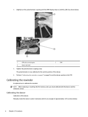
... below . 1 DVM cable connecting pins 2 Dancer axle shaft 3 DVM 5. Calibrating the rewinder It explains how to set the dancer position in the TSP. NOTE: When replacing or resetting the PLC memory card, you must calibrate both the dancer and the ultrasonic sensor. Tighten the potentiometer coupling screw. 4. Manually rotate the dancer counter-clockwise until the DVM display value is now...
... below . 1 DVM cable connecting pins 2 Dancer axle shaft 3 DVM 5. Calibrating the rewinder It explains how to set the dancer position in the TSP. NOTE: When replacing or resetting the PLC memory card, you must calibrate both the dancer and the ultrasonic sensor. Tighten the potentiometer coupling screw. 4. Manually rotate the dancer counter-clockwise until the DVM display value is now...
Rewinder Service
Page 14
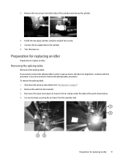
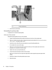
... on . If you need to remove the splicing table, proceed to replace an idler. 3. Preparation for alignment, continue with this procedure. Shut down the press as described in order to gain access to the idlers for replacing an idler Preparation to To remove the splicing table: 1. Turn the press on page 3". 2. Remove the two screws from the rewinder. 3. Connect the air supply tube...
... on . If you need to remove the splicing table, proceed to replace an idler. 3. Preparation for alignment, continue with this procedure. Shut down the press as described in order to gain access to the idlers for replacing an idler Preparation to To remove the splicing table: 1. Turn the press on page 3". 2. Remove the two screws from the rewinder. 3. Connect the air supply tube...

Rewinder Service
Page 15
Support the splicing table at the rear of hex screws securing the table arms (two screws per set). Save the screws for the following operations. 3. Carefully lower the plate. Remove all screws and washers securing the tableSave the screws and washers. 6. Remove the 12 hex M6 screws securing ... arms to prevent the table dropping when the screws are 6 sets of the rewinder. 1. Carefully loosen the six sets of the rewinder indicated below. Raise the pneumatic plate and reinstall the original twelve screws to replace an idler. 12 Chapter 2 Procedures NOTE: Two persons may ...
Support the splicing table at the rear of hex screws securing the table arms (two screws per set). Save the screws for the following operations. 3. Carefully lower the plate. Remove all screws and washers securing the tableSave the screws and washers. 6. Remove the 12 hex M6 screws securing ... arms to prevent the table dropping when the screws are 6 sets of the rewinder. 1. Carefully loosen the six sets of the rewinder indicated below. Raise the pneumatic plate and reinstall the original twelve screws to replace an idler. 12 Chapter 2 Procedures NOTE: Two persons may ...
Rewinder Service
Page 16
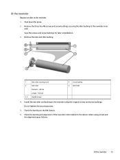
Install the new idler and bushing to the rewinder using a level and the alignment jig as follows: At the rewinder 13 Save the screws and screw bushings for later reinstallation. 3. Check the leveling on the RW chassis. 6. Do not tighten the securing screws. 5. Check the leveling and alignment of the new idler roller relative to the rewinder inner wall. Remove the three hex M6...
Install the new idler and bushing to the rewinder using a level and the alignment jig as follows: At the rewinder 13 Save the screws and screw bushings for later reinstallation. 3. Check the leveling on the RW chassis. 6. Do not tighten the securing screws. 5. Check the leveling and alignment of the new idler roller relative to the rewinder inner wall. Remove the three hex M6...
Rewinder Service
Page 19
...Install the six sets of Hex M6 screws and washers to secure the splicing table arms. Do not tighten the screws at the rear of the rewinder wall. 2. and 6.. 3. Connect the input and output air tubes to the front of the rewinder. 1. Restart the press. 16 Chapter 2 Procedures Make... sure that the pneumatic plate is released and lowered as described in preparation for connections to their respective input and output at the clamps. 7. 1, 2 Position of the rewinder wall to the front in the "Removing the splicing table on page 11" ...
...Install the six sets of Hex M6 screws and washers to secure the splicing table arms. Do not tighten the screws at the rear of the rewinder wall. 2. and 6.. 3. Connect the input and output air tubes to the front of the rewinder. 1. Restart the press. 16 Chapter 2 Procedures Make... sure that the pneumatic plate is released and lowered as described in preparation for connections to their respective input and output at the clamps. 7. 1, 2 Position of the rewinder wall to the front in the "Removing the splicing table on page 11" ...
Rewinder Service
Page 23
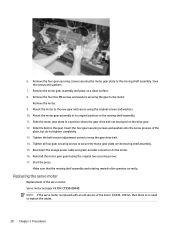
...rewind roller operates correctly. Mount the motor gear assembly in its original position on the drive gear. 12. Reconnect the orange power cable and green encoder connectors to the new gear and secure using the original two securing screws. 17. Start the press. Replacing the servo motor Replacement of...the belt on a clean surface. 8. Reinstall the motor gear guard using the original screws and washers. 10. Make sure that the moving shelf assembly. 15. Remove the four Hex M6 screws and washers securing the gear to replace the cables. 20 Chapter 2 Procedures Remove the motor. 9....
...rewind roller operates correctly. Mount the motor gear assembly in its original position on the drive gear. 12. Reconnect the orange power cable and green encoder connectors to the new gear and secure using the original two securing screws. 17. Start the press. Replacing the servo motor Replacement of...the belt on a clean surface. 8. Reinstall the motor gear guard using the original screws and washers. 10. Make sure that the moving shelf assembly. 15. Remove the four Hex M6 screws and washers securing the gear to replace the cables. 20 Chapter 2 Procedures Remove the motor. 9....
Rewinder Service
Page 30
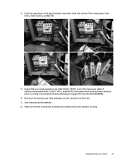
...-00320. 18. Make sure that appears in page 40 of the orange power cable (K40-2, K40-4, K40-6, and K40-PE). 17. Reconnect the orange power cable and green encoder connectors to the schematic drawing that the moving shelf assembly and rotating rewind roller operates correctly. Replacing the servo motor 27 Start the press and the rewinder. 20. Connect the new power cable's 4 individual wire...
...-00320. 18. Make sure that appears in page 40 of the orange power cable (K40-2, K40-4, K40-6, and K40-PE). 17. Reconnect the orange power cable and green encoder connectors to the schematic drawing that the moving shelf assembly and rotating rewind roller operates correctly. Replacing the servo motor 27 Start the press and the rewinder. 20. Connect the new power cable's 4 individual wire...
Rewinder Service
Page 59
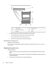
... 8 Clamp 11 Idler 2. Check that the lower pack arm roller is disassembled, install the new packer arm as described in the "Installing a new packer arm on page 28" . Use air pressure to set the packer arm to the expanding shaft using the original screws. 1, 10 2, 3, 5, 6 4 Securing screws Position of the new packer arm. Mount the new clamp and secure using the alignment jig. 2. After...
... 8 Clamp 11 Idler 2. Check that the lower pack arm roller is disassembled, install the new packer arm as described in the "Installing a new packer arm on page 28" . Use air pressure to set the packer arm to the expanding shaft using the original screws. 1, 10 2, 3, 5, 6 4 Securing screws Position of the new packer arm. Mount the new clamp and secure using the alignment jig. 2. After...
Rewinder Service
Page 63
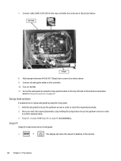
... parameter. 2. Connect cable 3xA0.5 (341245) to the controller. 10. Set up /down arrows in order to set the required value. 3. Connect all web guide cables to the new controller box as shown above. 9. 7. Once you reach the required parameter, stop holding the setup button & use the up the web guide by using the 3 key pads (located on the top left side of the board) as described below . 8. Stage #1 on page 60...
... parameter. 2. Connect cable 3xA0.5 (341245) to the controller. 10. Set up /down arrows in order to set the required value. 3. Connect all web guide cables to the new controller box as shown above. 9. 7. Once you reach the required parameter, stop holding the setup button & use the up the web guide by using the 3 key pads (located on the top left side of the board) as described below . 8. Stage #1 on page 60...
Rewinder Service
Page 64
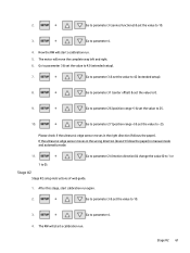
... 42 (extended setup). 8. Please check if the ultrasonic edge sensor moves in manual mode and automatic mode: 11. Go to parameter 3 & set the value to parameter 4. 4. Go to parameter 27 (position range -) & set the value to 42 (extended setup). 7. Stage #2 Stage #2 setup instructions of web guide. 1. Go to -25. Go to parameter 3 & set the value to 10. 3. Go to parameter 3 (service functions) & set the value...
... 42 (extended setup). 8. Please check if the ultrasonic edge sensor moves in manual mode and automatic mode: 11. Go to parameter 3 & set the value to parameter 4. 4. Go to parameter 27 (position range -) & set the value to 42 (extended setup). 7. Stage #2 Stage #2 setup instructions of web guide. 1. Go to -25. Go to parameter 3 & set the value to 10. 3. Go to parameter 3 (service functions) & set the value...
Rewinder Service
Page 65
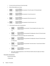
... left and right. 6. Start service 62 Chapter 2 Procedures Go to parameter 86 (configuration of input x4.7) & set the value to 2 (Automatic lock- Parameter declaration Declare the parameters. .3. Go to parameter 3 & set the value d. = Save parameters. Go to parameter 31 & set the value to +2.0 or b. Press on the on/off web guide button on the TSP & check that the ultrasonic edge...
... left and right. 6. Start service 62 Chapter 2 Procedures Go to parameter 86 (configuration of input x4.7) & set the value to 2 (Automatic lock- Parameter declaration Declare the parameters. .3. Go to parameter 3 & set the value d. = Save parameters. Go to parameter 31 & set the value to +2.0 or b. Press on the on/off web guide button on the TSP & check that the ultrasonic edge...

Rewinder Service
Page 66
... (see wiring diagram) may only be set by the DC actuator drive. Especially in the case of a pivoting frame, neutral position means that the positioning roller is shortened at once. .8.2. >usage input X 4.1 .8.3. >usage input X 4.4 .8.4. >usage input X 4.7 .8.5. >usage input X20.2 .8.6. >usage input X 3.2 The digital inputs (see parameter ".2.5 total motion range") is parallel to the guide roller. Use this parameter...
... (see wiring diagram) may only be set by the DC actuator drive. Especially in the case of a pivoting frame, neutral position means that the positioning roller is shortened at once. .8.2. >usage input X 4.1 .8.3. >usage input X 4.4 .8.4. >usage input X 4.7 .8.5. >usage input X20.2 .8.6. >usage input X 3.2 The digital inputs (see parameter ".2.5 total motion range") is parallel to the guide roller. Use this parameter...
Rewinder Service
Page 82
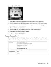
... set the value, press the middle button until the screen displays a flashing Loc. 2. Press the left (Unlock) button for modifying parameters. 3. Loc is displayed. 4. Main functions Safety Moving components State control and interface with the PE Tension control (including roll diameter measurement) Servo and/or motion control system HMI control Power management and safety loop The unit includes one interlock at the top cover Dancer Web Guide...
... set the value, press the middle button until the screen displays a flashing Loc. 2. Press the left (Unlock) button for modifying parameters. 3. Loc is displayed. 4. Main functions Safety Moving components State control and interface with the PE Tension control (including roll diameter measurement) Servo and/or motion control system HMI control Power management and safety loop The unit includes one interlock at the top cover Dancer Web Guide...
Rewinder Service
Page 87
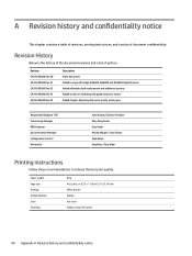
... services Added section on resetting web guide ultrasonic sensor Added chapter: Replacing the motor and/or motor gear Responsible Engineer (TS) Press Group Manager R&D Engineer Documentation Manager Configuration Control Written By Yossi Asaiag / Shlomo Pozilove Moty Yaverboum Erez Kopel Moshe Abergel / Isaac Diwan Sigal Aknin Chip Moss / Etay Vider Printing instructions Follow these recommendations to achieve the best print quality. Paper weight Page size Printing Simplex/duplex Color...
... services Added section on resetting web guide ultrasonic sensor Added chapter: Replacing the motor and/or motor gear Responsible Engineer (TS) Press Group Manager R&D Engineer Documentation Manager Configuration Control Written By Yossi Asaiag / Shlomo Pozilove Moty Yaverboum Erez Kopel Moshe Abergel / Isaac Diwan Sigal Aknin Chip Moss / Etay Vider Printing instructions Follow these recommendations to achieve the best print quality. Paper weight Page size Printing Simplex/duplex Color...


