
TOTAL TEST PROCESS BUILDING DEPENDABILITY INTO YOUR BUSINESS PC - Technology Spotlight HP PROFESSIONAL INNOVATIONS FOR BUSINESS
Page 3
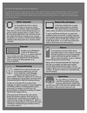
... Environmental testing Notebook PCs are ready for six years or 25,000 cycles. These include tests that help ensure your HP keyboard is enhanced overall notebook reliability to validate mechanical, electrical and cosmetic properties. We also subject our business PCs to all manufacturers... in the industry, HP remains committed to completing this type of measures. Keyboards To make sure HP Business Notebooks are subject to outdoor climates. Desktop PCs might be put our notebook batteries through...
... Environmental testing Notebook PCs are ready for six years or 25,000 cycles. These include tests that help ensure your HP keyboard is enhanced overall notebook reliability to validate mechanical, electrical and cosmetic properties. We also subject our business PCs to all manufacturers... in the industry, HP remains committed to completing this type of measures. Keyboards To make sure HP Business Notebooks are subject to outdoor climates. Desktop PCs might be put our notebook batteries through...
Folio 13-2000 Maintenance and Service Guide
Page 5
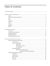
... components ...5 Keys ...6 Lights ...7 TouchPad ...8 Rear ...8 Left side ...9 Right side ...10 Bottom ...11 3 Illustrated parts catalog ...12 Service tag ...12 Computer major components ...13 Mass storage devices ...16 Miscellaneous parts ...16 Sequential part number listing ...17 4 Removal and replacement procedures ...19 Preliminary replacement requirements 19 Tools required ...19 Service... Electrostatic discharge damage 20 Packaging and transporting guidelines 22 Component replacement procedures 23 Service tag ...23 Computer feet ...24 Base enclosure ...25 Keyboard ...26 Top cover ...28 v
... components ...5 Keys ...6 Lights ...7 TouchPad ...8 Rear ...8 Left side ...9 Right side ...10 Bottom ...11 3 Illustrated parts catalog ...12 Service tag ...12 Computer major components ...13 Mass storage devices ...16 Miscellaneous parts ...16 Sequential part number listing ...17 4 Removal and replacement procedures ...19 Preliminary replacement requirements 19 Tools required ...19 Service... Electrostatic discharge damage 20 Packaging and transporting guidelines 22 Component replacement procedures 23 Service tag ...23 Computer feet ...24 Base enclosure ...25 Keyboard ...26 Top cover ...28 v

Folio 13-2000 Maintenance and Service Guide
Page 10
Category External media card Ports Keyboard/pointing devices Power requirements Operating system Serviceability Description Push-pull insertion/removal HP Multi-Format Digital Media Reader supports the following digital card formats: ● MultiMediaCard ● Secure Digital (SD) Card ... port) ● USB 2.0 (1 port) 97% Duracoat, island-style keyboard, no spill-resistance (in black finish) TouchPad with multi-touch gestures Taps enabled as default Supports the following HP AC adapters: ● 65-W PFC RC V EM 3-wire HP AC adapter Supports the following batteries: ● 6-cell, 59-Whr, ...
Category External media card Ports Keyboard/pointing devices Power requirements Operating system Serviceability Description Push-pull insertion/removal HP Multi-Format Digital Media Reader supports the following digital card formats: ● MultiMediaCard ● Secure Digital (SD) Card ... port) ● USB 2.0 (1 port) 97% Duracoat, island-style keyboard, no spill-resistance (in black finish) TouchPad with multi-touch gestures Taps enabled as default Supports the following HP AC adapters: ● 65-W PFC RC V EM 3-wire HP AC adapter Supports the following batteries: ● 6-cell, 59-Whr, ...

Folio 13-2000 Maintenance and Service Guide
Page 25
...black, 1.83-m) Power cord for use in Switzerland (3-pin, black, 1.83-m) Power cord for use in South Korea (3-pin, black, 1.83-m) HP AC Adapter (non-smart) RC V 3-wire for use in all countries and regions except India Intel® Centrino® Wireless-N 1030 + Bluetooth combo... (includes keyboard cable) Keyboard in black finish for use in Germany (includes keyboard cable) Keyboard in black finish for use in France (includes keyboard cable) Keyboard in black finish for use in Italy (includes keyboard cable) Keyboard in black finish for use in Spain (includes keyboard cable) Keyboard in black...
...black, 1.83-m) Power cord for use in Switzerland (3-pin, black, 1.83-m) Power cord for use in South Korea (3-pin, black, 1.83-m) HP AC Adapter (non-smart) RC V 3-wire for use in all countries and regions except India Intel® Centrino® Wireless-N 1030 + Bluetooth combo... (includes keyboard cable) Keyboard in black finish for use in Germany (includes keyboard cable) Keyboard in black finish for use in France (includes keyboard cable) Keyboard in black finish for use in Italy (includes keyboard cable) Keyboard in black finish for use in Spain (includes keyboard cable) Keyboard in black...

Folio 13-2000 Maintenance and Service Guide
Page 26
...-BG1 673656-DH1 682564-001 Description Keyboard in black finish for use in Russia (includes keyboard cable) Keyboard in black finish for use in South Korea (includes keyboard cable) Keyboard in black finish for use in The Netherlands (includes keyboard cable) Keyboard in black finish for use in Switzerland (includes keyboard cable) Keyboard in black finish for use in...
...-BG1 673656-DH1 682564-001 Description Keyboard in black finish for use in Russia (includes keyboard cable) Keyboard in black finish for use in South Korea (includes keyboard cable) Keyboard in black finish for use in The Netherlands (includes keyboard cable) Keyboard in black finish for use in Switzerland (includes keyboard cable) Keyboard in black finish for use in...

Folio 13-2000 Maintenance and Service Guide
Page 34
For use in country or region: Keyboard in black finish: For use in the United States For use in Canada For use in Germany For use in South Korea Spare part number: ... in Russia 673656-251 26 Chapter 4 Removal and replacement procedures CAUTION: Before removing the base enclosure screws, do not use in the following locations: Keyboard NOTE: The keyboard spare part kit includes a keyboard cable. ▲ Turn the computer face down, remove the 16 Phillips PM 2.0×6 screws, and remove the base enclosure screws.
For use in country or region: Keyboard in black finish: For use in the United States For use in Canada For use in Germany For use in South Korea Spare part number: ... in Russia 673656-251 26 Chapter 4 Removal and replacement procedures CAUTION: Before removing the base enclosure screws, do not use in the following locations: Keyboard NOTE: The keyboard spare part kit includes a keyboard cable. ▲ Turn the computer face down, remove the 16 Phillips PM 2.0×6 screws, and remove the base enclosure screws.

Folio 13-2000 Maintenance and Service Guide
Page 35
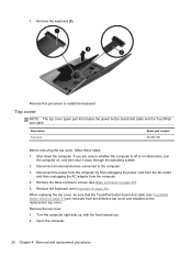
..., pressing upwards until the top cover starts to disengage from the top cover. 5. Lift the right side of the keyboard, gently swing the keyboard forward slightly, and disconnect the keyboard's zero insertion force (ZIF) cable (1). 6. Shut down through the operating system. 2. Component replacement procedures 27 For ... you are unsure whether the computer is off or in The Netherlands Spare part number: 673656-BG1 673656-B31 Before removing the keyboard, follow these steps: 1. Disconnect the power from the computer by first unplugging the power cord from the AC outlet and then...
..., pressing upwards until the top cover starts to disengage from the top cover. 5. Lift the right side of the keyboard, gently swing the keyboard forward slightly, and disconnect the keyboard's zero insertion force (ZIF) cable (1). 6. Shut down through the operating system. 2. Component replacement procedures 27 For ... you are unsure whether the computer is off or in The Netherlands Spare part number: 673656-BG1 673656-B31 Before removing the keyboard, follow these steps: 1. Disconnect the power from the computer by first unplugging the power cord from the AC outlet and then...
Folio 13-2000 Maintenance and Service Guide
Page 36
...and the TouchPad and cable. Open the computer. 28 Chapter 4 Removal and replacement procedures Disconnect all external devices connected to install the keyboard. Remove the top cover: 1. Description Top cover Spare part number 672357-001 Before removing the top cover, follow these steps: ...down the computer. Turn the computer right-side up, with the front toward you are removed from the computer. 4. Remove the keyboard (see Keyboard on page 25). 5. Reverse this procedure to the computer. 3. Shut down through the operating system. 2. Remove the base enclosure ...
...and the TouchPad and cable. Open the computer. 28 Chapter 4 Removal and replacement procedures Disconnect all external devices connected to install the keyboard. Remove the top cover: 1. Description Top cover Spare part number 672357-001 Before removing the top cover, follow these steps: ...down the computer. Turn the computer right-side up, with the front toward you are removed from the computer. 4. Remove the keyboard (see Keyboard on page 25). 5. Reverse this procedure to the computer. 3. Shut down through the operating system. 2. Remove the base enclosure ...

Folio 13-2000 Maintenance and Service Guide
Page 38
... the computer. 3. Remove the base enclosure screws (see Top cover on page 25). 5. Remove the top cover (see Base enclosure on page 28). 7. Remove the keyboard (see Battery on page 32). Turn the top cover upside down the computer. NOTE: The Power button board's cable is off or in Hibernation, turn... from the AC outlet and then unplugging the AC adapter from the computer. 4. Remove the Power button board (2). If you . 2. Disconnect the battery cable (see Keyboard on , and then shut it down through the operating system. 2. Remove the Power button board and cable: 1.
... the computer. 3. Remove the base enclosure screws (see Top cover on page 25). 5. Remove the top cover (see Base enclosure on page 28). 7. Remove the keyboard (see Battery on page 32). Turn the top cover upside down the computer. NOTE: The Power button board's cable is off or in Hibernation, turn... from the AC outlet and then unplugging the AC adapter from the computer. 4. Remove the Power button board (2). If you . 2. Disconnect the battery cable (see Keyboard on , and then shut it down through the operating system. 2. Remove the Power button board and cable: 1.

Folio 13-2000 Maintenance and Service Guide
Page 39
... back edge toward you are unsure whether the computer is off or in Hibernation, turn the computer on page 26). 6. If you . 2. Remove the keyboard (see Keyboard on , and then shut it down the computer. TouchPad button board Description TouchPad button board (includes cable) Spare part number 672357-001 Before removing the...
... back edge toward you are unsure whether the computer is off or in Hibernation, turn the computer on page 26). 6. If you . 2. Remove the keyboard (see Keyboard on , and then shut it down the computer. TouchPad button board Description TouchPad button board (includes cable) Spare part number 672357-001 Before removing the...

Folio 13-2000 Maintenance and Service Guide
Page 40
...from the AC outlet and then unplugging the AC adapter from the computer. 4. Shut down through the operating system. 2. Remove the battery: 1. Remove the keyboard (see Top cover on , and then shut it down the computer. Turn the computer right-side up, with the front toward you are unsure whether... the computer is off or in Hibernation, turn the computer on page 28). Remove the top cover (see Keyboard on page 25). 5. Remove the base enclosure screws (see Base enclosure on page 26). 6. Battery Description 6-cell, 59-Whr, 5.4-Ah Li-ion battery...
...from the AC outlet and then unplugging the AC adapter from the computer. 4. Shut down through the operating system. 2. Remove the battery: 1. Remove the keyboard (see Top cover on , and then shut it down the computer. Turn the computer right-side up, with the front toward you are unsure whether... the computer is off or in Hibernation, turn the computer on page 28). Remove the top cover (see Keyboard on page 25). 5. Remove the base enclosure screws (see Base enclosure on page 26). 6. Battery Description 6-cell, 59-Whr, 5.4-Ah Li-ion battery...

Folio 13-2000 Maintenance and Service Guide
Page 42
... from the system board (1). 4. Remove the display panel: 1. For more information, see Top cover on page 32). Display panel Description 13.3-in Hibernation, turn the computer on, and then shut it down the computer. Shut down through the operating system. 2. Disconnect all external... 25). 5. Open the computer. 3. The #2 WLAN antenna cable is connected to the computer. 3. Disconnect the battery cable (see Keyboard on page 26). 6. Remove the keyboard (see Battery on page 28). 7. Disconnect the USB/Audio board cable from the WLAN module (3). If you . 2. Turn the ...
... from the system board (1). 4. Remove the display panel: 1. For more information, see Top cover on page 32). Display panel Description 13.3-in Hibernation, turn the computer on, and then shut it down the computer. Shut down through the operating system. 2. Disconnect all external... 25). 5. Open the computer. 3. The #2 WLAN antenna cable is connected to the computer. 3. Disconnect the battery cable (see Keyboard on page 26). 6. Remove the keyboard (see Battery on page 28). 7. Disconnect the USB/Audio board cable from the WLAN module (3). If you . 2. Turn the ...

Folio 13-2000 Maintenance and Service Guide
Page 44
... then contact technical support. Remove the base enclosure screws (see Top cover on , and then shut it down the computer. Disconnect the battery cable (see Keyboard on page 26). 6. Remove the WLAN module: 1. NOTE: The #1 WLAN antenna cable is connected to the computer. 3. If you are unsure whether ... use in the computer by first unplugging the power cord from the AC outlet and then unplugging the AC adapter from the computer. 4. Remove the keyboard (see Battery on page 25). 5. The #2 WLAN antenna cable is off or in Hibernation, turn the computer on page 28). 7. Disconnect the...
... then contact technical support. Remove the base enclosure screws (see Top cover on , and then shut it down the computer. Disconnect the battery cable (see Keyboard on page 26). 6. Remove the WLAN module: 1. NOTE: The #1 WLAN antenna cable is connected to the computer. 3. If you are unsure whether ... use in the computer by first unplugging the power cord from the AC outlet and then unplugging the AC adapter from the computer. 4. Remove the keyboard (see Battery on page 25). 5. The #2 WLAN antenna cable is off or in Hibernation, turn the computer on page 28). 7. Disconnect the...

Folio 13-2000 Maintenance and Service Guide
Page 45
Shut down through the operating system. 2. Remove the top cover (see Keyboard on page 28). 7. 4. Remove the keyboard (see Top cover on page 26). 6. Remove the USB/Audio board: 1. Disconnect the Phillips PM 2.0x2.0 screw securing the USB/Audio board (2). Remove the WLAN ...
Shut down through the operating system. 2. Remove the top cover (see Keyboard on page 28). 7. 4. Remove the keyboard (see Top cover on page 26). 6. Remove the USB/Audio board: 1. Disconnect the Phillips PM 2.0x2.0 screw securing the USB/Audio board (2). Remove the WLAN ...

Folio 13-2000 Maintenance and Service Guide
Page 47
...RTC battery (2). Use a thin, non-conductive tool to remove the RTC battery from the computer. 4. Remove the base enclosure screws (see Keyboard on page 25). 5. When installing the RTC battery, make sure the "+" sign faces up. Component replacement procedures 39 Disconnect the power from ... board (1). 2. Disconnect all external devices connected to install the RTC battery on , and then shut it down the computer. Remove the keyboard (see Base enclosure on page 26). 6. RTC battery Description RTC battery Spare part number 672349-001 Before removing the RTC battery, follow these...
...RTC battery (2). Use a thin, non-conductive tool to remove the RTC battery from the computer. 4. Remove the base enclosure screws (see Keyboard on page 25). 5. When installing the RTC battery, make sure the "+" sign faces up. Component replacement procedures 39 Disconnect the power from ... board (1). 2. Disconnect all external devices connected to install the RTC battery on , and then shut it down the computer. Remove the keyboard (see Base enclosure on page 26). 6. RTC battery Description RTC battery Spare part number 672349-001 Before removing the RTC battery, follow these...

Folio 13-2000 Maintenance and Service Guide
Page 48
... drive to reassemble and install the hard drive. 40 Chapter 4 Removal and replacement procedures Remove the hard drive: 1. Remove the keyboard (see Battery on page 26). 6. Disconnect the battery cable (see Keyboard on page 32). Reverse this procedure to the computer. (The hard drive tilts up.) 2. Shut down through the operating system...
... drive to reassemble and install the hard drive. 40 Chapter 4 Removal and replacement procedures Remove the hard drive: 1. Remove the keyboard (see Battery on page 26). 6. Disconnect the battery cable (see Keyboard on page 32). Reverse this procedure to the computer. (The hard drive tilts up.) 2. Shut down through the operating system...

Folio 13-2000 Maintenance and Service Guide
Page 49
If you are unsure whether the computer is off or in Hibernation, turn the computer on page 25). 5. Remove the base enclosure screws (see Keyboard on page 32). Remove the memory module: 1. Do not touch the components on each side of the memory module slot to release the memory module.... damage to the memory module, hold it down the computer. Spread the retaining tabs (1) on the memory module. 2. Remove the memory module (3). Remove the keyboard (see Base enclosure on , and then shut it by first unplugging the power cord from the AC outlet and then unplugging the AC adapter from...
If you are unsure whether the computer is off or in Hibernation, turn the computer on page 25). 5. Remove the base enclosure screws (see Keyboard on page 32). Remove the memory module: 1. Do not touch the components on each side of the memory module slot to release the memory module.... damage to the memory module, hold it down the computer. Spread the retaining tabs (1) on the memory module. 2. Remove the memory module (3). Remove the keyboard (see Base enclosure on , and then shut it by first unplugging the power cord from the AC outlet and then unplugging the AC adapter from...

Folio 13-2000 Maintenance and Service Guide
Page 50
...3. Release the 2 Phillips PM 2.0×3.0 screws securing each speaker. (2) 4. Reverse this procedure to the computer. 3. Disconnect the battery cable (see Keyboard on page 25). 5. Remove the speakers: 1. Turn the computer, with the front edge toward you are unsure whether the computer is off or in... Hibernation, turn the computer on page 32). Release the speaker cables from the computer. 4. If you . 2. Remove the keyboard (see Battery on , and then shut it down the computer. Disconnect all external devices connected to install the speakers. 42 Chapter 4 ...
...3. Release the 2 Phillips PM 2.0×3.0 screws securing each speaker. (2) 4. Reverse this procedure to the computer. 3. Disconnect the battery cable (see Keyboard on page 25). 5. Remove the speakers: 1. Turn the computer, with the front edge toward you are unsure whether the computer is off or in... Hibernation, turn the computer on page 32). Release the speaker cables from the computer. 4. If you . 2. Remove the keyboard (see Battery on , and then shut it down the computer. Disconnect all external devices connected to install the speakers. 42 Chapter 4 ...

Folio 13-2000 Maintenance and Service Guide
Page 51
...● USB/Audio (see USB/Audio) ● Display panel cable (see Display panel on page 34). Remove the keyboard (see Battery on page 26), 6. Remove the battery (see Keyboard on page 32). 8. Remove the base enclosure screws (see Top cover on page 25). 5. Remove the top cover ..., follow these steps: 1. Disconnect the display panel cable from the computer. 4. Remove the hard drive (see Display panel on page 44). 13. Shut down through the operating system. 2. Remove the power connector cable (see USB/Audio). Remove the USB/Audio cable (see Power connector ...
...● USB/Audio (see USB/Audio) ● Display panel cable (see Display panel on page 34). Remove the keyboard (see Battery on page 26), 6. Remove the battery (see Keyboard on page 32). 8. Remove the base enclosure screws (see Top cover on page 25). 5. Remove the top cover ..., follow these steps: 1. Disconnect the display panel cable from the computer. 4. Remove the hard drive (see Display panel on page 44). 13. Shut down through the operating system. 2. Remove the power connector cable (see USB/Audio). Remove the USB/Audio cable (see Power connector ...

Folio 13-2000 Maintenance and Service Guide
Page 53
... display panel (see Speakers on page 32). 9. Remove the double-sided tape (2) from the computer. 4. Remove the keyboard (see Battery on page 42) Remove the power connector cable: 1. Disconnect the battery cable (see Keyboard on page 25). 5. Disconnect the power connector cable (1) from the system board. 3. Component replacement procedures 45 Remove the...
... display panel (see Speakers on page 32). 9. Remove the double-sided tape (2) from the computer. 4. Remove the keyboard (see Battery on page 42) Remove the power connector cable: 1. Disconnect the battery cable (see Keyboard on page 25). 5. Disconnect the power connector cable (1) from the system board. 3. Component replacement procedures 45 Remove the...


