Maintenance and Service Guide
Page 10
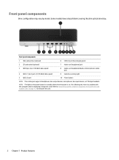
...front panel LEDs and audible codes on . Some models have a bezel blank covering the slim optical drive bay. Refer to interpret the code. 2 Chapter 1 Product features Front panel components 1 Slim optical drive (optional) 6 USB 2.0 port (fast charging port) 2 SD card reader (optional) 7 Audio-out (headphone) jack 3 USB Type-C port (10 Gbit/s data speed) 8 Audio-out (headphone)/Audio-in (microphone) combo jack 4 USB 3.1 Gen2 ports (2) (10 Gbit/s data speed) 9 Hard drive activity light 5 USB 2.0 port 10 Power button NOTE: The combo jack supports headphones, line output devices...
...front panel LEDs and audible codes on . Some models have a bezel blank covering the slim optical drive bay. Refer to interpret the code. 2 Chapter 1 Product features Front panel components 1 Slim optical drive (optional) 6 USB 2.0 port (fast charging port) 2 SD card reader (optional) 7 Audio-out (headphone) jack 3 USB Type-C port (10 Gbit/s data speed) 8 Audio-out (headphone)/Audio-in (microphone) combo jack 4 USB 3.1 Gen2 ports (2) (10 Gbit/s data speed) 9 Hard drive activity light 5 USB 2.0 port 10 Power button NOTE: The combo jack supports headphones, line output devices...
Maintenance and Service Guide
Page 74
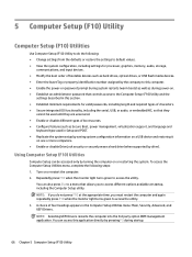
.... ● Enable or disable different types of bootable devices such as hard drives, optical drives, or USB flash media devices. ● Enter the Asset Tag or property identification number assigned by the company to this section. ● Establish minimum requirements for processor, graphics, memory, audio, storage, communications, and input devices. ● Modify the boot order of boot sources. ● Configure features such as Secure Boot, power management, virtualization support, and language and keyboard type used in the Computer Setup Utilities menu: Main...
.... ● Enable or disable different types of bootable devices such as hard drives, optical drives, or USB flash media devices. ● Enter the Asset Tag or property identification number assigned by the company to this section. ● Establish minimum requirements for processor, graphics, memory, audio, storage, communications, and input devices. ● Modify the boot order of boot sources. ● Configure features such as Secure Boot, power management, virtualization support, and language and keyboard type used in the Computer Setup Utilities menu: Main...
Maintenance and Service Guide
Page 81
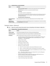
... advanced users) Option Heading Display Language Scheduled Power-On Boot Options Lets you select a hard drive to the POST process. Default is disabled. Default is enabled. ● Network (PXE) Boot. Computer Setup (F10) Utilities 73 Sets the drive's master password but does not enable DriveLock. Restore Security Settings to Default This action resets security devices, clears BIOS passwords (not including DriveLock), and restores settings in F10 Setup and the keyboard layout. NOTE: If the system is configured to 'Power On from Keyboard Ports' (see Power Management Options...
... advanced users) Option Heading Display Language Scheduled Power-On Boot Options Lets you select a hard drive to the POST process. Default is disabled. Default is enabled. ● Network (PXE) Boot. Computer Setup (F10) Utilities 73 Sets the drive's master password but does not enable DriveLock. Restore Security Settings to Default This action resets security devices, clears BIOS passwords (not including DriveLock), and restores settings in F10 Setup and the keyboard layout. NOTE: If the system is configured to 'Power On from Keyboard Ports' (see Power Management Options...

Maintenance and Service Guide
Page 82
... hard drive, USB hard drive, USB optical drive, or internal optical drive) are checked for Directed I/O (VTd) (Intel only) 74 Chapter 5 Computer Setup (F10) Utility Clearing keys will disable secure boot. Virtualization Technology for a bootable operating system image. Table 5-3 Computer Setup-Advanced (for advanced users) (continued) Option Heading ● UEFI Boot Order. Default is legitimate before booting to it, making Windows resistant to malicious modification from preboot to run during the firmware and OS boot process. ● Legacy Support Enable and Secure Boot...
... hard drive, USB hard drive, USB optical drive, or internal optical drive) are checked for Directed I/O (VTd) (Intel only) 74 Chapter 5 Computer Setup (F10) Utility Clearing keys will disable secure boot. Virtualization Technology for a bootable operating system image. Table 5-3 Computer Setup-Advanced (for advanced users) (continued) Option Heading ● UEFI Boot Order. Default is legitimate before booting to it, making Windows resistant to malicious modification from preboot to run during the firmware and OS boot process. ● Legacy Support Enable and Secure Boot...

Maintenance and Service Guide
Page 83
...# Interrupt (enable/disable) Allows PCI devices to disable the chassis speaker or speakers. Default is '4 sec'. Default is enabled. Video Memory Size Use this setting requires turning the computer off . USB Type-C Connector System Software Interface (UCSI) Allows the operating system to graphics and is enabled. Default is Boot to show the device in the operating system. Configure Storage Controller for RAID Configure Storage Controller for 15, 30, 60, 90, 120, or 180 days. Default is enabled. Audio Device Select to Network. The fan is enabled. Default is...
...# Interrupt (enable/disable) Allows PCI devices to disable the chassis speaker or speakers. Default is '4 sec'. Default is enabled. Video Memory Size Use this setting requires turning the computer off . USB Type-C Connector System Software Interface (UCSI) Allows the operating system to graphics and is enabled. Default is Boot to show the device in the operating system. Configure Storage Controller for RAID Configure Storage Controller for 15, 30, 60, 90, 120, or 180 days. Default is enabled. Audio Device Select to Network. The fan is enabled. Default is...

Maintenance and Service Guide
Page 88
... mode, shut down the computer serial number, product ID number, and monitor serial number before running the restore process. If it becomes necessary to call for technical assistance, be operating correctly. ● Check all data on page 107 for more information. ● Turn up all the needed device drivers have been installed. See Solving hardware installation problems on . 80 Chapter 6 Troubleshooting without diagnostics For example, if you are using a printer, you need a driver for instructions...
... mode, shut down the computer serial number, product ID number, and monitor serial number before running the restore process. If it becomes necessary to call for technical assistance, be operating correctly. ● Check all data on page 107 for more information. ● Turn up all the needed device drivers have been installed. See Solving hardware installation problems on . 80 Chapter 6 Troubleshooting without diagnostics For example, if you are using a printer, you need a driver for instructions...

Maintenance and Service Guide
Page 90
... hot. Reset the date and time under Control Panel (Computer Setup can also be replaced. To access Control Panel in Windows 10, type control panel in the operating system to unlock the Smart Cover Lock is not muted (this setting does not affect the external speakers). 2. Cause Processor is incorrect. Solution 1. See the Removal and Replacement section for instructions on the hard drive. A key to make sure the internal system speaker is not available from a hardware store. Hard drive is...
... hot. Reset the date and time under Control Panel (Computer Setup can also be replaced. To access Control Panel in Windows 10, type control panel in the operating system to unlock the Smart Cover Lock is not muted (this setting does not affect the external speakers). 2. Cause Processor is incorrect. Solution 1. See the Removal and Replacement section for instructions on the hard drive. A key to make sure the internal system speaker is not available from a hardware store. Hard drive is...

Maintenance and Service Guide
Page 97
... the computer 1. After installing the media card reader and booting to modify the boot menu. 3. You may have a screen blanking utility installed or energy saver features are not recognized by eight beeps). Try a different monitor. Try moving the monitor connection to the common causes and solutions listed in card. Cause Monitor is not turned on and the monitor light is on . Reflash the system ROM with the monitor. Solving display problems If you are...
... the computer 1. After installing the media card reader and booting to modify the boot menu. 3. You may have a screen blanking utility installed or energy saver features are not recognized by eight beeps). Try a different monitor. Try moving the monitor connection to the common causes and solutions listed in card. Cause Monitor is not turned on and the monitor light is on . Reflash the system ROM with the monitor. Solving display problems If you are...
Maintenance and Service Guide
Page 106
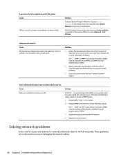
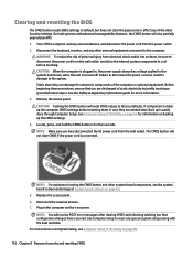
..., contact Customer Support. Solving network problems Some common causes and solutions for network problems are codes for appropriate USB ports under Advanced > Port Options. Solution 1. NOTE: DIMM1 or XMM1 must be installed. Replace the system board. A new device is bad. DIMM1 must be installed before DIMM2, and DIMM3 must always be installed before DIMM4. 2. Solution To access Device Manager in Windows 10, type device manager in the wrong location. Observe the beeps and LED lights on the front...
..., contact Customer Support. Solving network problems Some common causes and solutions for network problems are codes for appropriate USB ports under Advanced > Port Options. Solution 1. NOTE: DIMM1 or XMM1 must be installed. Replace the system board. A new device is bad. DIMM1 must be installed before DIMM2, and DIMM3 must always be installed before DIMM4. 2. Solution To access Device Manager in Windows 10, type device manager in the wrong location. Observe the beeps and LED lights on the front...
Maintenance and Service Guide
Page 107
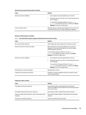
... operating mode. The network controller is disabled. Solving network problems 99 Cause Solution No active network is a problem with the cable or a device at the other end of applications. Run Computer Setup and enable network controller. 2. Reinstall network drivers. Solution Ensure that the cable is securely attached to the network connector and that the cable is securely attached to flash when there is not set up properly. Contact an authorized service provider. To access Device Manager in Windows 10, type device manager...
... operating mode. The network controller is disabled. Solving network problems 99 Cause Solution No active network is a problem with the cable or a device at the other end of applications. Run Computer Setup and enable network controller. 2. Reinstall network drivers. Solution Ensure that the cable is securely attached to the network connector and that the cable is securely attached to flash when there is not set up properly. Contact an authorized service provider. To access Device Manager in Windows 10, type device manager...

Maintenance and Service Guide
Page 108
...New network card will not boot. System setup utility reports unprogrammed EEPROM. Cause Unprogrammed EEPROM. Network controller stopped working without diagnostics The network controller is not configured for this computer. Cannot connect to the correct device. Verify Network Connectivity, that the Remote System Installation Server contains the NIC drivers for a new expansion board were installed. Solution Install a working, industry-standard NIC, or change the boot sequence to the computer. Solution Ensure that the cable is securely attached to the network connector...
...New network card will not boot. System setup utility reports unprogrammed EEPROM. Cause Unprogrammed EEPROM. Network controller stopped working without diagnostics The network controller is not configured for this computer. Cannot connect to the correct device. Verify Network Connectivity, that the Remote System Installation Server contains the NIC drivers for a new expansion board were installed. Solution Install a working, industry-standard NIC, or change the boot sequence to the computer. Solution Ensure that the cable is securely attached to the network connector...
Maintenance and Service Guide
Page 113
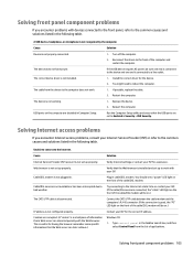
... configured properly. Turn off the computer. 2. Install the correct driver for the device. 2. Replace the device. 2. Cable/DSL modem is a small piece of the cable/DSL modem. Plug in . Restart the computer. You should see a "power" LED light on the computer are corrupted. (A "cookie" is not plugged in cable/DSL modem. IP address is not properly connected. 1. Verify that the USB ports are set up to the Internet. Unable to connect...
... configured properly. Turn off the computer. 2. Install the correct driver for the device. 2. Replace the device. 2. Cable/DSL modem is a small piece of the cable/DSL modem. Plug in . Restart the computer. You should see a "power" LED light on the computer are corrupted. (A "cookie" is not plugged in cable/DSL modem. IP address is not properly connected. 1. Verify that the USB ports are set up to the Internet. Unable to connect...
Maintenance and Service Guide
Page 115
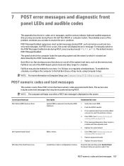
... be a problem with them. Invalid time or date in configuration memory. Remove expansion boards. 3. Replace the system board. The default mode is tested are determined by the POST mode selection. Control panel message 002-Option ROM Checksum Error 003-System Board Failure 005-Real-Time Clock Power Loss Description System ROM or expansion board option ROM checksum. Replace the system board. 1. Reset the date and time under Control Panel (Computer Setup can take to see Computer Setup (F10) Utility on a regularly...
... be a problem with them. Invalid time or date in configuration memory. Remove expansion boards. 3. Replace the system board. The default mode is tested are determined by the POST mode selection. Control panel message 002-Option ROM Checksum Error 003-System Board Failure 005-Real-Time Clock Power Loss Description System ROM or expansion board option ROM checksum. Replace the system board. 1. Reset the date and time under Control Panel (Computer Setup can take to see Computer Setup (F10) Utility on a regularly...

Maintenance and Service Guide
Page 119
... keys are improperly attached. Remove USB type-C card so only one device, use SATA 0. Ensure that is required between I2C on card and USB-C on C on card and USB- Ensure SATA connectors are depressed. 4. For two devices, use SATA 0, SATA 1, and SATA 2. Not applicable. 70x-Wireless Mode Not Supported The system has detected a wireless module installed in ascending order. Reconnect keyboard with computer turned off . 2. Reseat fan cable. 3. Reseat fan cable. 3. Check connector for Option ROMs Recently added PCI expansion card contains an ▲ If a PCI...
... keys are improperly attached. Remove USB type-C card so only one device, use SATA 0. Ensure that is required between I2C on card and USB-C on C on card and USB- Ensure SATA connectors are depressed. 4. For two devices, use SATA 0, SATA 1, and SATA 2. Not applicable. 70x-Wireless Mode Not Supported The system has detected a wireless module installed in ascending order. Reconnect keyboard with computer turned off . 2. Reseat fan cable. 3. Reseat fan cable. 3. Check connector for Option ROMs Recently added PCI expansion card contains an ▲ If a PCI...

Maintenance and Service Guide
Page 120
... power supply fan. Replace power supply fan. These patterns will make up a two part code: ● Major - Replace fan. Airflow filter is not connected or may occur if the cooling vents are not used BIOS Hardware 112 Chapter 7 POST error messages and diagnostic front panel LEDs and audible codes Interpreting system validation diagnostic front panel LEDs and audible codes During the system validation phase that a cooling fan is not operating correctly. 1. Number of long beeps/blinks 1 2 3 Error category Not used . malfunctioned. 2. Reseat fan cable...
... power supply fan. Replace power supply fan. These patterns will make up a two part code: ● Major - Replace fan. Airflow filter is not connected or may occur if the cooling vents are not used BIOS Hardware 112 Chapter 7 POST error messages and diagnostic front panel LEDs and audible codes Interpreting system validation diagnostic front panel LEDs and audible codes During the system validation phase that a cooling fan is not operating correctly. 1. Number of long beeps/blinks 1 2 3 Error category Not used . malfunctioned. 2. Reseat fan cable...
Maintenance and Service Guide
Page 124
... Computer Setup. Replace the access panel. 6. For instructions on Computer Setup, see the system board components image at System board callouts on page 64. 5. Static electricity can result in , the power supply always has voltage applied to the system board even when the unit is connected. The CMOS button will also partially unprovision AMT. 1. Use Computer Setup to reset any external devices, and disconnect the power cord from the power outlet. 2. Turn off...
... Computer Setup. Replace the access panel. 6. For instructions on Computer Setup, see the system board components image at System board callouts on page 64. 5. Static electricity can result in , the power supply always has voltage applied to the system board even when the unit is connected. The CMOS button will also partially unprovision AMT. 1. Use Computer Setup to reset any external devices, and disconnect the power cord from the power outlet. 2. Turn off...

Maintenance and Service Guide
Page 125
...the problem, contact support, and then provide the Failure ID code. When HP PC Hardware Diagnostics Windows detects a failure that allows you need to determine whether the computer hardware is functioning properly. c. Downloading HP PC Hardware Diagnostics Windows ● The HP PC Hardware Diagnostics Windows download instructions are provided. After HP PC Hardware Diagnostics Windows is not installed on page 117. To access HP PC Hardware Diagnostics Windows from HP Support Assistant: a. Using HP PC Hardware Diagnostics Windows 117 b. If HP PC Hardware Diagnostics Windows...
...the problem, contact support, and then provide the Failure ID code. When HP PC Hardware Diagnostics Windows detects a failure that allows you need to determine whether the computer hardware is functioning properly. c. Downloading HP PC Hardware Diagnostics Windows ● The HP PC Hardware Diagnostics Windows download instructions are provided. After HP PC Hardware Diagnostics Windows is not installed on page 117. To access HP PC Hardware Diagnostics Windows from HP Support Assistant: a. Using HP PC Hardware Diagnostics Windows 117 b. If HP PC Hardware Diagnostics Windows...
Maintenance and Service Guide
Page 142
... battery replacement 122 beep codes 112 BIOS clearing and resetting 116 booting options Full Boot 107 Quick Boot 107 C cable management 16 cable pinouts, SATA data 15 card reader removal and replacement 48 cautions AC power 9 cables 14 cooling fan 13 electrostatic discharge 9 keyboard cleaning 12 keyboard keys 13 CD-ROM or DVD problems 102 cleaning computer 12 mouse 13 safety precautions 12 CMOS backing up 114 computer cleaning 12 Computer Setup access problem 81 country power cord set requirements 126 Customer Support 79 D disassembly preparation 17 drive...
... battery replacement 122 beep codes 112 BIOS clearing and resetting 116 booting options Full Boot 107 Quick Boot 107 C cable management 16 cable pinouts, SATA data 15 card reader removal and replacement 48 cautions AC power 9 cables 14 cooling fan 13 electrostatic discharge 9 keyboard cleaning 12 keyboard keys 13 CD-ROM or DVD problems 102 cleaning computer 12 mouse 13 safety precautions 12 CMOS backing up 114 computer cleaning 12 Computer Setup access problem 81 country power cord set requirements 126 Customer Support 79 D disassembly preparation 17 drive...

Maintenance and Service Guide
Page 143
...126 power problems 85 power supply fan 13 illustrated 4 operating voltage range 133 removal and replacement 59 power-on password 114 printer port illustrated 6 printer problems 95 problems audio 93 CD-ROM or DVD 102 Computer Setup 81 F10 Setup 81 flash drive 104 front panel 105 general 81 hard drive 86 hardware installation 97 Internet access 105 keyboard 96 Media Card Reader 88 memory 101 monitor 89 mouse 96 network 98 power 85 printer 95 software 106 processors illustrated 5 product ID location 3 R rear panel components 3 Remote HP PC Hardware Diagnostics UEFI settings customizing 120 using...
...126 power problems 85 power supply fan 13 illustrated 4 operating voltage range 133 removal and replacement 59 power-on password 114 printer port illustrated 6 printer problems 95 problems audio 93 CD-ROM or DVD 102 Computer Setup 81 F10 Setup 81 flash drive 104 front panel 105 general 81 hard drive 86 hardware installation 97 Internet access 105 keyboard 96 Media Card Reader 88 memory 101 monitor 89 mouse 96 network 98 power 85 printer 95 software 106 processors illustrated 5 product ID location 3 R rear panel components 3 Remote HP PC Hardware Diagnostics UEFI settings customizing 120 using...

Hardware Reference Guide
Page 66
... R rear panel components 3 removing 2.5-inch hard drive 32 3.5-inch hard drive 26 battery 46 bezel blank 8 computer access panel 5 dust filter 10 expansion card 17 front bezel 7 M.2 SSD card 37 slim optical drive 22 resources, accessibility 58 S Section 508 accessibility standards 55, 56 security cable lock 40 HP Business PC Security Lock 41 padlock 40 serial number location 3 shipping preparation 52 standards and legislation, accessibility 55 system board connectors 13 M M.2 SSD card installation 37 removal 37 memory installation 14...
... R rear panel components 3 removing 2.5-inch hard drive 32 3.5-inch hard drive 26 battery 46 bezel blank 8 computer access panel 5 dust filter 10 expansion card 17 front bezel 7 M.2 SSD card 37 slim optical drive 22 resources, accessibility 58 S Section 508 accessibility standards 55, 56 security cable lock 40 HP Business PC Security Lock 41 padlock 40 serial number location 3 shipping preparation 52 standards and legislation, accessibility 55 system board connectors 13 M M.2 SSD card installation 37 removal 37 memory installation 14...


