

Getting Started Guide
Page 6
... the software ...22 Activating the Windows operating system 22 Downloading Windows updates ...22 Customizing the monitor display ...22 Turning off the computer ...23 If you encounter issues ...23 Performing basic troubleshooting ...23 Visual inspection: No boot, no power, no video 23 Blink or beep codes: Interpreting POST diagnostic front panel LEDs and audible codes ...24 HP Support Assistant ...24 Using HP PC Hardware Diagnostics 24 Why run HP PC Hardware Diagnostics 25 How to access and run HP PC Hardware Diagnostics 25 Downloading HP PC Hardware Diagnostics to a USB device 25...
... the software ...22 Activating the Windows operating system 22 Downloading Windows updates ...22 Customizing the monitor display ...22 Turning off the computer ...23 If you encounter issues ...23 Performing basic troubleshooting ...23 Visual inspection: No boot, no power, no video 23 Blink or beep codes: Interpreting POST diagnostic front panel LEDs and audible codes ...24 HP Support Assistant ...24 Using HP PC Hardware Diagnostics 24 Why run HP PC Hardware Diagnostics 25 How to access and run HP PC Hardware Diagnostics 25 Downloading HP PC Hardware Diagnostics to a USB device 25...

Getting Started Guide
Page 11
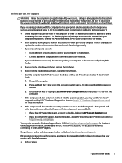
... using a printer, you need a driver for interpretation and recommended action. Blink or beep codes: Interpreting POST diagnostic front panel LEDs and audible codes If you see flashing LEDs on the front of the computer or if you hear beeps, see the Maintenance and Service Guide (English only) for that printer model. ● Remove any bootable media (CD/DVD or USB device) from the system before taking further action: ● Be sure that HP...
... using a printer, you need a driver for interpretation and recommended action. Blink or beep codes: Interpreting POST diagnostic front panel LEDs and audible codes If you see flashing LEDs on the front of the computer or if you hear beeps, see the Maintenance and Service Guide (English only) for that printer model. ● Remove any bootable media (CD/DVD or USB device) from the system before taking further action: ● Be sure that HP...
Getting Started Guide
Page 13
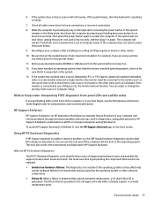
... Maintenance and Service Guide (English only) for details. ● If the screen is blank, plug the monitor into an AC power source, voltage is also available). ◦ If you have HP Support Assistant installed, access HP Instant Support Professional Edition at http://www.hp.com/go /bizsupport for a series of beeps emanating from the wall outlet and allow the internal system components to cool before the operating system starts...
... Maintenance and Service Guide (English only) for details. ● If the screen is blank, plug the monitor into an AC power source, voltage is also available). ◦ If you have HP Support Assistant installed, access HP Instant Support Professional Edition at http://www.hp.com/go /bizsupport for a series of beeps emanating from the wall outlet and allow the internal system components to cool before the operating system starts...

Getting Started Guide
Page 17
... backups you use the System Recovery program. See System Restore on -screen instructions. Run System Recovery from the drive. The recovery image is a file that you have to reset your preferences. ● When backing up to discs, number each disc after removing it from a recovery image stored on your hard drive. To continue a task, select the appropriate option. Follow the on-screen instructions to create system recovery DVDs or USB flash drive, you can order a recovery disc set up your...
... backups you use the System Recovery program. See System Restore on -screen instructions. Run System Recovery from the drive. The recovery image is a file that you have to reset your preferences. ● When backing up to discs, number each disc after removing it from a recovery image stored on your hard drive. To continue a task, select the appropriate option. Follow the on-screen instructions to create system recovery DVDs or USB flash drive, you can order a recovery disc set up your...
Getting Started Guide
Page 23
... these ports, the monitor will either schedule support or provide replacement parts. If you hear beeps, see flashing LEDs on the system. 13. Reconfigure your computer and resolve problems through automated updates and tune-ups, built-in Computer Setup. Remove any bootable media (CD/DVD or USB device) from issues that may be connected to one of your computer after installing a non-Plug and Play expansion board or other video ports are disabled...
... these ports, the monitor will either schedule support or provide replacement parts. If you hear beeps, see flashing LEDs on the system. 13. Reconfigure your computer and resolve problems through automated updates and tune-ups, built-in Computer Setup. Remove any bootable media (CD/DVD or USB device) from issues that may be connected to one of your computer after installing a non-Plug and Play expansion board or other video ports are disabled...

Getting Started Guide
Page 32
... using a printer, you need a driver for at least four seconds. This tool also works with components not diagnosed in HP Support Assistant. 24 Chapter 3 Getting started in again. During boot, the other than the factory-installed operating system, check to be sure that it on all HP or Compaq computers running Windows 10. Blink or beep codes: Interpreting POST diagnostic front panel LEDs and audible codes If you see the Maintenance and Service Guide...
... using a printer, you need a driver for at least four seconds. This tool also works with components not diagnosed in HP Support Assistant. 24 Chapter 3 Getting started in again. During boot, the other than the factory-installed operating system, check to be sure that it on all HP or Compaq computers running Windows 10. Blink or beep codes: Interpreting POST diagnostic front panel LEDs and audible codes If you see the Maintenance and Service Guide...

Maintenance and Service Guide 1
Page 63
.... Changing this setting alters the Secure Boot key list to disable multi-processor support under the operating system. Enable MS UEFI CA key Disabling this setting requires turning the computer off all legacy support on the computer, including booting to DOS, running legacy graphics cards, booting to factory defaults Default is enabled. Set this option to 'disable' to find a valid boot source. Recover after Boot Failure Allows the system to initiate recovery after failing to support Device Guard. Default is enabled. Secure Boot Configuration Configure Legacy Support...
.... Changing this setting alters the Secure Boot key list to disable multi-processor support under the operating system. Enable MS UEFI CA key Disabling this setting requires turning the computer off all legacy support on the computer, including booting to DOS, running legacy graphics cards, booting to factory defaults Default is enabled. Set this option to 'disable' to find a valid boot source. Recover after Boot Failure Allows the system to initiate recovery after failing to support Device Guard. Default is enabled. Secure Boot Configuration Configure Legacy Support...

Maintenance and Service Guide 1
Page 64
...USB Type-C Connector System Software Interface (UCSI) Select to enable communication of seconds you disable the wireless module slot. Default is enabled. LAN/WLAN Auto Switching 56 Chapter 5 Computer Setup (F10) Utility Default is enabled. Default is enabled. Increase Idle Fan Speed(%) Sets idle fan speed percentage. Table 5-3 Computer Setup-Advanced (for advanced users) (continued) Option Heading PCI Express Slot x (enable/disable) Lets you choose is allocated permanently to graphics and is unavailable to the operating system. Video Memory Size Use this option...
...USB Type-C Connector System Software Interface (UCSI) Select to enable communication of seconds you disable the wireless module slot. Default is enabled. LAN/WLAN Auto Switching 56 Chapter 5 Computer Setup (F10) Utility Default is enabled. Default is enabled. Increase Idle Fan Speed(%) Sets idle fan speed percentage. Table 5-3 Computer Setup-Advanced (for advanced users) (continued) Option Heading PCI Express Slot x (enable/disable) Lets you choose is allocated permanently to graphics and is unavailable to the operating system. Video Memory Size Use this option...

Maintenance and Service Guide 1
Page 76
... the device if the reader was just installed into the computer and you will lose any key or click the mouse button and type your password (if set). If you encounter display problems, see the documentation that the monitor light is corrupted; Bad monitor. The cable connections are enabled. System ROM is on for more than four seconds. Solution Turn on . In Control Panel, select Category from the inserted media card during boot or...
... the device if the reader was just installed into the computer and you will lose any key or click the mouse button and type your password (if set). If you encounter display problems, see the documentation that the monitor light is corrupted; Bad monitor. The cable connections are enabled. System ROM is on for more than four seconds. Solution Turn on . In Control Panel, select Category from the inserted media card during boot or...

Maintenance and Service Guide 1
Page 84
... surfaces, be installed before touching. Beeps and flashing LEDs are using the correct memory modules and to verify the proper installation. A plug and play board may need to reconfigure the computer when you add or remove hardware, such as part of the new hardware. Review the documentation that appear on the computer are unplugged. Reboot the computer and follow the instructions that came with other devices. Run the Computer Setup utility and ensure...
... surfaces, be installed before touching. Beeps and flashing LEDs are using the correct memory modules and to verify the proper installation. A plug and play board may need to reconfigure the computer when you add or remove hardware, such as part of the new hardware. Review the documentation that appear on the computer are unplugged. Reboot the computer and follow the instructions that came with other devices. Run the Computer Setup utility and ensure...

Maintenance and Service Guide 1
Page 86
... autosense the network. Network controller stopped working when an expansion board was added to the computer. Ensure that the other end of applications. Contact an authorized service provider. Cause Solution To access Device Manager in Windows 10, type device manager in the taskbar search box, and then select Device Manager from the list of the cable. Diagnostics reports a failure. The network controller is securely attached to the network connector and that the cable and device at...
... autosense the network. Network controller stopped working when an expansion board was added to the computer. Ensure that the other end of applications. Contact an authorized service provider. Cause Solution To access Device Manager in Windows 10, type device manager in the taskbar search box, and then select Device Manager from the list of the cable. Diagnostics reports a failure. The network controller is securely attached to the network connector and that the cable and device at...

Maintenance and Service Guide 1
Page 92
... in configuration memory. Clear CMOS. (See Password security and resetting CMOS on page 91.) 5. Remove expansion boards. 3. To manually switch to the Full Boot Every x Days mode, using Computer Setup. Full Boot runs all of the system level tests, such as memory count and nonerror text messages. NOTE: For more information on page 47. 7 POST error messages and diagnostic front panel LEDs and audible codes This appendix lists the error codes, error messages, and the various indicator light and...
... in configuration memory. Clear CMOS. (See Password security and resetting CMOS on page 91.) 5. Remove expansion boards. 3. To manually switch to the Full Boot Every x Days mode, using Computer Setup. Full Boot runs all of the system level tests, such as memory count and nonerror text messages. NOTE: For more information on page 47. 7 POST error messages and diagnostic front panel LEDs and audible codes This appendix lists the error codes, error messages, and the various indicator light and...

Maintenance and Service Guide 1
Page 93
... memory configuration, and reboot the computer. 4. Use Computer Setup to proper version. 2. If the memory configuration was recently changed , unplug the power cord, restore the original memory configuration, and reboot the computer. 4. Unplug the power cord, re-seat the memory modules, and reboot the computer. 3. Upgrade BIOS to update this information. 1. See the Removal and Replacement section for instructions on installing a new battery. 1. If the error persists, replace the system board. 1. Control panel message 008-Microcode Patch Error 009-PMM Allocation Error...
... memory configuration, and reboot the computer. 4. Use Computer Setup to proper version. 2. If the memory configuration was recently changed , unplug the power cord, restore the original memory configuration, and reboot the computer. 4. Unplug the power cord, re-seat the memory modules, and reboot the computer. 3. Upgrade BIOS to update this information. 1. See the Removal and Replacement section for instructions on installing a new battery. 1. If the error persists, replace the system board. 1. Control panel message 008-Microcode Patch Error 009-PMM Allocation Error...

Maintenance and Service Guide 1
Page 96
...43A-USB Type-C I2C Not Connected Cable is installed. 500-BIOS Recovery A system BIOS recovery has occurred. Reconnect keyboard with computer turned off . 2. Reconnect the keyboard with computer turned off . 2. Reseat fan cable. 3. Replace chassis, rear chassis, or front chassis fan. 903-Computer Cover Has Been Removed Since N/A Last System Startup 904-SATA Cabling Error One or more SATA devices are depressed. 3. If the error reoccurs, the device may not work with a supported module. 800-Keyboard Error Keyboard failure. 1. For two devices, use SATA 0, SATA 1, and SATA 2. 88...
...43A-USB Type-C I2C Not Connected Cable is installed. 500-BIOS Recovery A system BIOS recovery has occurred. Reconnect keyboard with computer turned off . 2. Reconnect the keyboard with computer turned off . 2. Reseat fan cable. 3. Replace chassis, rear chassis, or front chassis fan. 903-Computer Cover Has Been Removed Since N/A Last System Startup 904-SATA Cabling Error One or more SATA devices are depressed. 3. If the error reoccurs, the device may not work with a supported module. 800-Keyboard Error Keyboard failure. 1. For two devices, use SATA 0, SATA 1, and SATA 2. 88...

Maintenance and Service Guide 1
Page 97
... have 1. Replace power supply fan. Reseat power supply fan. the category of long and short blinks, accompanied by long and short beeps (where applicable) are not used BIOS Hardware Interpreting system validation diagnostic front panel LEDs and audible codes 89 Reseat fan cable. 3. malfunctioned. 2. Replace the airflow filter. The machine should return to identify the error. The system BIOS has detected your machine was previously shut down to avoid overheating. the specific error within the...
... have 1. Replace power supply fan. Reseat power supply fan. the category of long and short blinks, accompanied by long and short beeps (where applicable) are not used BIOS Hardware Interpreting system validation diagnostic front panel LEDs and audible codes 89 Reseat fan cable. 3. malfunctioned. 2. Replace the airflow filter. The machine should return to identify the error. The system BIOS has detected your machine was previously shut down to avoid overheating. the specific error within the...

Maintenance and Service Guide 1
Page 101
... system board components, see Computer Setup (F10) Utility on backing up the computer CMOS settings before touching. Plug in for five seconds. The CMOS button will receive POST error messages after clearing CMOS and rebooting advising you that you have occurred. Clearing and resetting the BIOS The CMOS button resets BIOS settings to default, but does not clear the passwords or affect any other external equipment connected to the computer. Clearing and resetting the BIOS 93 WARNING! Failure to...
... system board components, see Computer Setup (F10) Utility on backing up the computer CMOS settings before touching. Plug in for five seconds. The CMOS button will receive POST error messages after clearing CMOS and rebooting advising you that you have occurred. Clearing and resetting the BIOS The CMOS button resets BIOS settings to default, but does not clear the passwords or affect any other external equipment connected to the computer. Clearing and resetting the BIOS 93 WARNING! Failure to...
Maintenance and Service Guide 1
Page 102
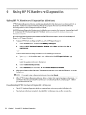
... Start button, and then select HP Help and Support. b. Select Diagnostics, and then select HP PC Hardware Diagnostics Windows. 2. c. When the tool opens, select the type of diagnostic test you to run , and then follow these steps to determine whether the computer hardware is installed, follow the on-screen instructions. b. To access HP PC Hardware Diagnostics Windows from HP Support Assistant: a. Downloading HP PC Hardware Diagnostics Windows ● The HP PC Hardware Diagnostics Windows download instructions are provided. 94 Chapter 9 Using HP PC Hardware Diagnostics Type...
... Start button, and then select HP Help and Support. b. Select Diagnostics, and then select HP PC Hardware Diagnostics Windows. 2. c. When the tool opens, select the type of diagnostic test you to run , and then follow these steps to determine whether the computer hardware is installed, follow the on-screen instructions. b. To access HP PC Hardware Diagnostics Windows from HP Support Assistant: a. Downloading HP PC Hardware Diagnostics Windows ● The HP PC Hardware Diagnostics Windows download instructions are provided. 94 Chapter 9 Using HP PC Hardware Diagnostics Type...

Maintenance and Service Guide 1
Page 116
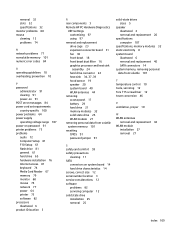
... codes 89 audio problems 72 B battery disposal 13 installation 29 removal 29 battery replacement 29 beep codes 89 BIOS clearing and resetting 93 booting options Full Boot 84 Quick Boot 84 C cautions AC power 8 electrostatic discharge 8 keyboard cleaning 11 keyboard keys 12 cleaning computer 11 mouse 12 safety precautions 11 CMOS backing up 91 computer specifications 107 computer cleaning 11 Computer Setup access problem 61 country power cord set requirements 100 Customer Support 59 D disassembly preparation 16 108 Index drive cage removal and replacement...
... codes 89 audio problems 72 B battery disposal 13 installation 29 removal 29 battery replacement 29 beep codes 89 BIOS clearing and resetting 93 booting options Full Boot 84 Quick Boot 84 C cautions AC power 8 electrostatic discharge 8 keyboard cleaning 11 keyboard keys 12 cleaning computer 11 mouse 12 safety precautions 11 CMOS backing up 91 computer specifications 107 computer cleaning 11 Computer Setup access problem 61 country power cord set requirements 100 Customer Support 59 D disassembly preparation 16 108 Index drive cage removal and replacement...
Maintenance and Service Guide 1
Page 117
... power cord set requirements country specific 100 power problems 64 power supply operating voltage range 107 power-on password 91 printer problems 73 problems audio 72 Computer Setup 61 F10 Setup 61 flash drive 81 general 61 hard drive 65 hardware installation 76 Internet access 81 keyboard 74 Media Card Reader 67 memory 79 monitor 68 mouse 74 network 77 power 64 printer 73 software 82 processors illustrated 6 product ID location 3 R rear components 3 Remote HP PC Hardware Diagnostics UEFI settings customizing 97 using 97 removal and replacement drive cage 23 expansion connector board 31 fan...
... power cord set requirements country specific 100 power problems 64 power supply operating voltage range 107 power-on password 91 printer problems 73 problems audio 72 Computer Setup 61 F10 Setup 61 flash drive 81 general 61 hard drive 65 hardware installation 76 Internet access 81 keyboard 74 Media Card Reader 67 memory 79 monitor 68 mouse 74 network 77 power 64 printer 73 software 82 processors illustrated 6 product ID location 3 R rear components 3 Remote HP PC Hardware Diagnostics UEFI settings customizing 97 using 97 removal and replacement drive cage 23 expansion connector board 31 fan...

Hardware Reference Guide
Page 5
... ...5 Installing a security lock ...6 Connecting the power cord ...7 3 Hardware upgrades ...8 Serviceability features ...8 Warnings and cautions ...8 Removing the computer access panel ...9 Replacing the computer access panel ...10 Upgrading system memory ...11 Memory module specifications ...11 Installing memory modules ...12 Removing a hard drive ...16 Installing a hard drive ...17 Replacing an M.2 PCIe solid state drive (SSD) ...18 Replacing the WLAN module ...25 Installing an external antenna ...32 Replacing the battery ...38 Synchronizing the optional wireless keyboard and mouse 44...
... ...5 Installing a security lock ...6 Connecting the power cord ...7 3 Hardware upgrades ...8 Serviceability features ...8 Warnings and cautions ...8 Removing the computer access panel ...9 Replacing the computer access panel ...10 Upgrading system memory ...11 Memory module specifications ...11 Installing memory modules ...12 Removing a hard drive ...16 Installing a hard drive ...17 Replacing an M.2 PCIe solid state drive (SSD) ...18 Replacing the WLAN module ...25 Installing an external antenna ...32 Replacing the battery ...38 Synchronizing the optional wireless keyboard and mouse 44...


