HP Notebook Reference Guide
Page 82
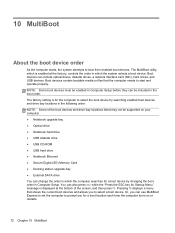
... or files that shows the current boot devices and allows you for a boot location each time the computer turns on your computer. ● Notebook upgrade bay ● Optical drive ● Notebook hard drive ● USB diskette drive ● USB CD-ROM ● USB hard drive ● Notebook... Ethernet ● Secure Digital (SD) Memory Card ● Docking station upgrade bay ● External SATA drive You can change the order in which is displayed at the factory, controls the order in Computer Setup. Pressing f9 ...
... or files that shows the current boot devices and allows you for a boot location each time the computer turns on your computer. ● Notebook upgrade bay ● Optical drive ● Notebook hard drive ● USB diskette drive ● USB CD-ROM ● USB hard drive ● Notebook... Ethernet ● Secure Digital (SD) Memory Card ● Docking station upgrade bay ● External SATA drive You can change the order in which is displayed at the factory, controls the order in Computer Setup. Pressing f9 ...

RAID User Guide
Page 7
... 1 allows data to a designated recovery drive. RAID 5 RAID 5 distributes data across both drives. Recovery also enables docking and undocking of the HP Advanced Docking Station (see Devices supported on page 7). RAID modes supported 3 RAID 0 RAID 0 stripes, or distributes, data across three hard drives... RAID modes supported by inserting a second SATA hard drive into the Upgrade Bay, eSATA port (if available), or the second hard drive bay (if available) of the computer, or into the SATA-swappable bay of the computer if the second drive is read simultaneously from both drives...
... 1 allows data to a designated recovery drive. RAID 5 RAID 5 distributes data across both drives. Recovery also enables docking and undocking of the HP Advanced Docking Station (see Devices supported on page 7). RAID modes supported 3 RAID 0 RAID 0 stripes, or distributes, data across three hard drives... RAID modes supported by inserting a second SATA hard drive into the Upgrade Bay, eSATA port (if available), or the second hard drive bay (if available) of the computer, or into the SATA-swappable bay of the computer if the second drive is read simultaneously from both drives...

RAID User Guide
Page 11
... devices supported Operating systems supported HP RAID supports 32-bit and 64-bit versions of the secondary (or third) drive will be usable in a RAID configuration. RAID 0 RAID 1 Recovery RAID 5 Primary and Upgrade Bay SATA hard drives in the computer Primary and secondary bay SATA hard drives in the Upgrade Bay to create a RAID volume. If...
... devices supported Operating systems supported HP RAID supports 32-bit and 64-bit versions of the secondary (or third) drive will be usable in a RAID configuration. RAID 0 RAID 1 Recovery RAID 5 Primary and Upgrade Bay SATA hard drives in the computer Primary and secondary bay SATA hard drives in the Upgrade Bay to create a RAID volume. If...

RAID User Guide
Page 12
... devices supported Regarding the capacity of a SATA drive using Intel® Rapid Storage Technology software (v10 and higher) and a second SATA drive in the Upgrade Bay. HP Business computers Select HP Business computers support RAID using a standard USB 2.0 interface. The following illustration shows a supported computer with the primary hard drive (1) and a secondary hard drive...
... devices supported Regarding the capacity of a SATA drive using Intel® Rapid Storage Technology software (v10 and higher) and a second SATA drive in the Upgrade Bay. HP Business computers Select HP Business computers support RAID using a standard USB 2.0 interface. The following illustration shows a supported computer with the primary hard drive (1) and a secondary hard drive...

RAID User Guide
Page 18
The loss of power during RAID migration can result in the SATA-swappable bay of data. 14 Chapter 5 RAID volume setup CAUTION: Make sure that a supported hard drive is connected to the eSATA port of the computer (see Intel ...® Smart Response Technology, please see Devices supported on page 10 before initiating the following instructions assume that the computer is installed in the computer Upgrade Bay, in the loss of the docking station, or connected to AC power before setting up RAID volumes. The basic RAID migration steps are as follows...
The loss of power during RAID migration can result in the SATA-swappable bay of data. 14 Chapter 5 RAID volume setup CAUTION: Make sure that a supported hard drive is connected to the eSATA port of the computer (see Intel ...® Smart Response Technology, please see Devices supported on page 10 before initiating the following instructions assume that the computer is installed in the computer Upgrade Bay, in the loss of the docking station, or connected to AC power before setting up RAID volumes. The basic RAID migration steps are as follows...

RAID User Guide
Page 28
NOTE: RAID 5 requires 3 hard drives in the computer: the primary hard drive, the secondary hard drive, and the upgrade bay hard drive. 1. Create a volume name (or use for the RAID 5 array, and then click Next. 24 Chapter 5 RAID volume setup Click Create, select Efficient data ... the suggested name), select the three hard drives to an additional external USB hard drive. Migrating to RAID 5 (select models only) NOTE: When using an HP-supplied image, migrating to RAID 5 requires you begin.
NOTE: RAID 5 requires 3 hard drives in the computer: the primary hard drive, the secondary hard drive, and the upgrade bay hard drive. 1. Create a volume name (or use for the RAID 5 array, and then click Next. 24 Chapter 5 RAID volume setup Click Create, select Efficient data ... the suggested name), select the three hard drives to an additional external USB hard drive. Migrating to RAID 5 (select models only) NOTE: When using an HP-supplied image, migrating to RAID 5 requires you begin.

RAID User Guide
Page 36
If you wish to return the primary hard drive in a RAID 0 or RAID 5 volume to the docking station's bay. After you complete the procedure, you must also reset both drives to Non-RAID, and then press enter. NOTE: A RAID 0 or RAID 5 volume cannot be ... access the Intel Option ROM and reset both drives to non-RAID status if you need to move the RAID recovery drive from the computer's upgrade bay to non-RAID status, you must reinstall the operating system on or restart the computer. You must first back up or down arrow key to...
If you wish to return the primary hard drive in a RAID 0 or RAID 5 volume to the docking station's bay. After you complete the procedure, you must also reset both drives to Non-RAID, and then press enter. NOTE: A RAID 0 or RAID 5 volume cannot be ... access the Intel Option ROM and reset both drives to non-RAID status if you need to move the RAID recovery drive from the computer's upgrade bay to non-RAID status, you must reinstall the operating system on or restart the computer. You must first back up or down arrow key to...
Getting Started HP Notebook
Page 6
...Intel Smart Response Technology (select models only 28 Removing the hard drive ...29 Installing a hard drive ...31 Replacing a drive in the upgrade bay 33 Replacing a hard drive ...33 Replacing an optical drive 34 Adding or replacing memory modules 35 Adding or replacing the memory module ... display 43 Cleaning the sides and cover 43 Cleaning the TouchPad and keyboard 43 6 Backup and recovery ...45 Creating recovery media with HP Recovery Disc Creator 45 Creating recovery media ...46 Backing up your information ...46 Performing a system recovery ...47 Using the Windows recovery ...
...Intel Smart Response Technology (select models only 28 Removing the hard drive ...29 Installing a hard drive ...31 Replacing a drive in the upgrade bay 33 Replacing a hard drive ...33 Replacing an optical drive 34 Adding or replacing memory modules 35 Adding or replacing the memory module ... display 43 Cleaning the sides and cover 43 Cleaning the TouchPad and keyboard 43 6 Backup and recovery ...45 Creating recovery media with HP Recovery Disc Creator 45 Creating recovery media ...46 Backing up your information ...46 Performing a system recovery ...47 Using the Windows recovery ...

Getting Started HP Notebook
Page 18
... USB 3.0 compatible devices and provide enhanced USB power performance. Connects an external VGA monitor or projector. (5) Smart card reader Supports optional smart cards. (6) Upgrade bay (optical drive shown) The upgrade bay can hold a protective insert, a hard drive, or an optical drive that reads an optical disc. Connects an optional computer headset microphone, stereo array...
... USB 3.0 compatible devices and provide enhanced USB power performance. Connects an external VGA monitor or projector. (5) Smart card reader Supports optional smart cards. (6) Upgrade bay (optical drive shown) The upgrade bay can hold a protective insert, a hard drive, or an optical drive that reads an optical disc. Connects an optional computer headset microphone, stereo array...

Getting Started HP Notebook
Page 41
... (see Inserting or removing the battery on , in the Sleep state, or in Hibernation. Loosen the upgrade bay screw (1). 9. Turn the computer upside down on a flat surface, with the upgrade bay toward you are not sure whether the computer is on page 26). 7. Shut down the computer through ...remove the hard drive while the computer is off or in the upgrade bay The upgrade bay can hold either a hard drive or an optical drive. To remove a hard drive from the upgrade bay. Unplug the power cord from the upgrade bay (3). Remove the battery (see Removing or replacing the service door ...
... (see Inserting or removing the battery on , in the Sleep state, or in Hibernation. Loosen the upgrade bay screw (1). 9. Turn the computer upside down on a flat surface, with the upgrade bay toward you are not sure whether the computer is on page 26). 7. Shut down the computer through ...remove the hard drive while the computer is off or in the upgrade bay The upgrade bay can hold either a hard drive or an optical drive. To remove a hard drive from the upgrade bay. Unplug the power cord from the upgrade bay (3). Remove the battery (see Removing or replacing the service door ...

Getting Started HP Notebook
Page 42
..., turn the computer on page 26). 5. 2. Remove the optical drive from the AC outlet. 5. Insert the hard drive (1) into the upgrade bay, and then tighten the upgrade bay screw (2). 3. Turn the computer right-side up, and then reconnect AC power and external devices to the computer. 4. If you . 6.... To remove an optical drive from the upgrade bay. Save your work. 2. Shut down on a flat surface, with the upgrade bay toward you are not sure whether the computer is on page 27). 8. Turn the computer upside down the ...
..., turn the computer on page 26). 5. 2. Remove the optical drive from the AC outlet. 5. Insert the hard drive (1) into the upgrade bay, and then tighten the upgrade bay screw (2). 3. Turn the computer right-side up, and then reconnect AC power and external devices to the computer. 4. If you . 6.... To remove an optical drive from the upgrade bay. Save your work. 2. Shut down on a flat surface, with the upgrade bay toward you are not sure whether the computer is on page 27). 8. Turn the computer upside down the ...

Getting Started HP Notebook
Page 43
...). 5. Adding or replacing memory modules The computer has two or four memory module slots depending on a flat surface, with the upgrade bay toward you. 2. Additionally, quad-core computers also include two memory module slots under the service door. Turn the computer right-side... AC power and external devices to the computer. 7. Tighten the upgrade bay screw (2). 4. Turn the computer upside down on processor configuration. The capacity of the computer can be upgraded Replacing a drive in the upgrade bay: 1. Two memory module slots are located under the keyboard. Insert...
...). 5. Adding or replacing memory modules The computer has two or four memory module slots depending on a flat surface, with the upgrade bay toward you. 2. Additionally, quad-core computers also include two memory module slots under the service door. Turn the computer right-side... AC power and external devices to the computer. 7. Tighten the upgrade bay screw (2). 4. Turn the computer upside down on processor configuration. The capacity of the computer can be upgraded Replacing a drive in the upgrade bay: 1. Two memory module slots are located under the keyboard. Insert...

Getting Started HP Notebook
Page 45
... an electrostatic-safe container. 7. Align the notched edge (1) of the memory module compartment, press the module (2) into the memory module slot until it in the upgrade bay 37 Grasp the edge of the memory module (2), and then gently pull the memory module out of the memory module slot.
... an electrostatic-safe container. 7. Align the notched edge (1) of the memory module compartment, press the module (2) into the memory module slot until it in the upgrade bay 37 Grasp the edge of the memory module (2), and then gently pull the memory module out of the memory module slot.

Getting Started HP Notebook
Page 47
... rest the keyboard on the keyboard release cut-out (2). To avoid disconnecting the keyboard cable, do not pull the keyboard away from the upgrade bay (see Replacing a drive in the upgrade bay 39 Turn the computer right-side up and gently release the tabs along the top edge of the computer. Remove the keyboard...
... rest the keyboard on the keyboard release cut-out (2). To avoid disconnecting the keyboard cable, do not pull the keyboard away from the upgrade bay (see Replacing a drive in the upgrade bay 39 Turn the computer right-side up and gently release the tabs along the top edge of the computer. Remove the keyboard...

Getting Started HP Notebook
Page 49
b. NOTE: Gently push along the top of the keyboard to ensure all tabs are in the upgrade bay 41 10. c. Press gently on the base enclosure. Replacing a drive in place. Lift up the keyboard and flip it over (1), resting it on the keyboard(3) so that it snaps into the base enclosure slots. Replace the keyboard: a. Slide the keyboard tabs (2) into place.
b. NOTE: Gently push along the top of the keyboard to ensure all tabs are in the upgrade bay 41 10. c. Press gently on the base enclosure. Replacing a drive in place. Lift up the keyboard and flip it over (1), resting it on the keyboard(3) so that it snaps into the base enclosure slots. Replace the keyboard: a. Slide the keyboard tabs (2) into place.

Getting Started HP Notebook
Page 50
...point/color temperature, and luminance/brightness. ▲ To access Mobile Display Assistant, click the Mobile Display Assistant icon in the upgrade bay on the computer. You can use this program to receive automatic update notifications when they become available. 42 Chapter 5 Maintenance Go... download the latest versions. Using the DreamColor display (select models only) Computer models with the latest versions. Updating programs and drivers HP recommends that you update your programs and drivers on page 26.) 13. Replace the service door (see Inserting or removing the battery...
...point/color temperature, and luminance/brightness. ▲ To access Mobile Display Assistant, click the Mobile Display Assistant icon in the upgrade bay on the computer. You can use this program to receive automatic update notifications when they become available. 42 Chapter 5 Maintenance Go... download the latest versions. Using the DreamColor display (select models only) Computer models with the latest versions. Updating programs and drivers HP recommends that you update your programs and drivers on page 26.) 13. Replace the service door (see Inserting or removing the battery...

Getting Started HP Notebook
Page 61
... buttons 4 on/off button 7 using 21 TouchPad gestures pinching 24 scrolling 24 zooming 24 TouchPad light, identifying 5 TouchPad zone identifying 4 traveling with the computer 50 U upgrade bay 10 USB 3.0 port 10 USB charging port 11 USB ports, identifying 10, 11 V vents, identifying 11, 14 volume keys, identifying 20 W webcam 13 webcam light...
... buttons 4 on/off button 7 using 21 TouchPad gestures pinching 24 scrolling 24 zooming 24 TouchPad light, identifying 5 TouchPad zone identifying 4 traveling with the computer 50 U upgrade bay 10 USB 3.0 port 10 USB charging port 11 USB ports, identifying 10, 11 V vents, identifying 11, 14 volume keys, identifying 20 W webcam 13 webcam light...

HP EliteBook 8570w Mobile Workstation Maintenance and Service Guide
Page 6
... Memory Modules (under service door 53 RTC battery ...55 WLAN module ...56 WWAN module ...59 Bluetooth module ...61 Hard drive ...63 Smart card reader 66 Upgrade bay device 68 Keyboard ...72 Memory Modules (under keyboard 74 Top cover ...76 Power button board 79 Function button board 81 Fingerprint reader board 83 TouchPad...
... Memory Modules (under service door 53 RTC battery ...55 WLAN module ...56 WWAN module ...59 Bluetooth module ...61 Hard drive ...63 Smart card reader 66 Upgrade bay device 68 Keyboard ...72 Memory Modules (under keyboard 74 Top cover ...76 Power button board 79 Function button board 81 Fingerprint reader board 83 TouchPad...

HP EliteBook 8570w Mobile Workstation Maintenance and Service Guide
Page 11
Category Upgrade bay Microphone Audio Webcam Modem Ethernet Wireless Description Supports the following 6.35 cm (2.5 in) SATA III solid-state drives: ● 256 GB Self Encrypting Drive ● ...
Category Upgrade bay Microphone Audio Webcam Modem Ethernet Wireless Description Supports the following 6.35 cm (2.5 in) SATA III solid-state drives: ● 256 GB Self Encrypting Drive ● ...

HP EliteBook 8570w Mobile Workstation Maintenance and Service Guide
Page 22
... When a device is connected to optional powered stereo speakers, headphones, earbuds, a headset, or television audio. The upgrade bay can hold a protective insert, a hard drive, or an optical drive that reads an optical disc. Releases the disc... Right Component (1) Audio-out (headphone) jack (2) Audio-in (microphone) jack (3) USB 3.0 ports (2) (4) External monitor port (5) Smart card reader (6) Upgrade bay (optical drive shown) (7) Optical drive eject button (select models only) Description Produces sound when connected to the jack, the computer speakers are disabled. WARNING...
... When a device is connected to optional powered stereo speakers, headphones, earbuds, a headset, or television audio. The upgrade bay can hold a protective insert, a hard drive, or an optical drive that reads an optical disc. Releases the disc... Right Component (1) Audio-out (headphone) jack (2) Audio-in (microphone) jack (3) USB 3.0 ports (2) (4) External monitor port (5) Smart card reader (6) Upgrade bay (optical drive shown) (7) Optical drive eject button (select models only) Description Produces sound when connected to the jack, the computer speakers are disabled. WARNING...


