Service Guide
Page 6
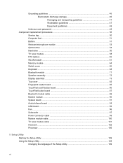
.../off button board 86 TouchPad button board ...87 Bluetooth module cable ...88 Modem module ...90 System board ...91 Audio/infrared board ...94 USB board ...95 Fan ...96 Subwoofer ...97 Power connector cable ...99 Modem module cable ...100 TV tuner module cable ...101 Heat sink ...102 Processor ...106 5 Setup Utility Starting the...
.../off button board 86 TouchPad button board ...87 Bluetooth module cable ...88 Modem module ...90 System board ...91 Audio/infrared board ...94 USB board ...95 Fan ...96 Subwoofer ...97 Power connector cable ...99 Modem module cable ...100 TV tuner module cable ...101 Heat sink ...102 Processor ...106 5 Setup Utility Starting the...
Service Guide
Page 22
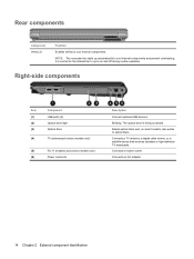
Blinking: The optical drive is normal for the internal fan to cool internal components and prevent overheating. Reads optical discs and, on and off during routine operation. Connects a modem cable. Right-side components Item (1) (2) (3) (4) (5) (6) Component ... Enables airflow to optical discs. Connects a TV antenna, a digital cable device, or a satellite device that receives standard or high-definition TV broadcasts. NOTE: The computer fan starts up automatically to cycle on select models, also writes to cool internal components. It is being accessed.
Blinking: The optical drive is normal for the internal fan to cool internal components and prevent overheating. Reads optical discs and, on and off during routine operation. Connects a modem cable. Right-side components Item (1) (2) (3) (4) (5) (6) Component ... Enables airflow to optical discs. Connects a TV antenna, a digital cable device, or a satellite device that receives standard or high-definition TV broadcasts. NOTE: The computer fan starts up automatically to cycle on select models, also writes to cool internal components. It is being accessed.
Service Guide
Page 24
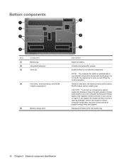
... (5) Battery release latch Description Holds the battery. Enable airflow to restore computer functionality, and then contact technical support through Help and Support. NOTE: The computer fan starts up automatically to cycle on and off during routine operation. It is normal for use in the computer by the governmental agency that regulates... wireless devices in your country or region. CAUTION: To prevent an unresponsive system, replace the wireless module only with a wireless module authorized for the internal fan to cool internal components and prevent overheating.
... (5) Battery release latch Description Holds the battery. Enable airflow to restore computer functionality, and then contact technical support through Help and Support. NOTE: The computer fan starts up automatically to cycle on and off during routine operation. It is normal for use in the computer by the governmental agency that regulates... wireless devices in your country or region. CAUTION: To prevent an unresponsive system, replace the wireless module only with a wireless module authorized for the internal fan to cool internal components and prevent overheating.
Service Guide
Page 32
... NTSC/ATSC/ANG TV tuner module 482899-001 TV tuner external antenna cables (not illustrated): With F-PAL jack 482900-002 With PAL jack 482900-001 Fans: For use only with computer models equipped graphics subsystems with AMD processors 488885-001 24 Chapter 3 Illustrated parts catalog Item (16) (17) (18) (19) Description...
... NTSC/ATSC/ANG TV tuner module 482899-001 TV tuner external antenna cables (not illustrated): With F-PAL jack 482900-002 With PAL jack 482900-001 Fans: For use only with computer models equipped graphics subsystems with AMD processors 488885-001 24 Chapter 3 Illustrated parts catalog Item (16) (17) (18) (19) Description...
Service Guide
Page 46
... board for use only with computer models equipped with Intel processors (includes cable) Rubber Kit (includes 6 base enclosure rubber feet) Fan for use only with computer models equipped with Intel processors Display enclosure for use only with computer models equipped with AntiGlare display assembies ...802.11a/b/g and 802.11b/g WLAN modules (includes 2 wireless antenna transceivers and cables) AMD Turion Ultra ZM80 2.10-GHz processor (includes replacement thermal material) AMD Turion Ultra ZM82 2.20-GHz processor (includes replacement thermal material) 38 Chapter 3 Illustrated parts catalog
... board for use only with computer models equipped with Intel processors (includes cable) Rubber Kit (includes 6 base enclosure rubber feet) Fan for use only with computer models equipped with Intel processors Display enclosure for use only with computer models equipped with AntiGlare display assembies ...802.11a/b/g and 802.11b/g WLAN modules (includes 2 wireless antenna transceivers and cables) AMD Turion Ultra ZM80 2.10-GHz processor (includes replacement thermal material) AMD Turion Ultra ZM82 2.20-GHz processor (includes replacement thermal material) 38 Chapter 3 Illustrated parts catalog
Service Guide
Page 49
... equipped with a BrightView display assemblhy and 802.11a/b/g and 802.11b/g WLAN modules (includes 2 wireless antenna transceivers and cables and logo LED board and cable) Fan for use only with computer models equipped with Intel processors in Antigua and Barbuda, Barbados, Belize, Canada, the Cayman Islands, Guam, Puerto Rico, Trinidad and...
... equipped with a BrightView display assemblhy and 802.11a/b/g and 802.11b/g WLAN modules (includes 2 wireless antenna transceivers and cables and logo LED board and cable) Fan for use only with computer models equipped with Intel processors in Antigua and Barbuda, Barbados, Belize, Canada, the Cayman Islands, Guam, Puerto Rico, Trinidad and...
Service Guide
Page 101
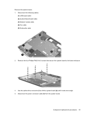
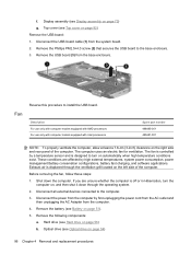
Component replacement procedures 93 Remove the four Phillips PM2.5×4.0 screws that secure the system board to lift the system board (2) until it rests at an angle. 4. Disconnect the following cables: (1) USB board cable (2) Audio/infrared board cable (3) Modem module cable (4) Fan cable (5) Subwoofer cable 2. Disconnect the power connector cable (3) from the system board. Use the optical drive connector (1) to the base enclosure. 3. Remove the system board: 1.
Component replacement procedures 93 Remove the four Phillips PM2.5×4.0 screws that secure the system board to lift the system board (2) until it rests at an angle. 4. Disconnect the following cables: (1) USB board cable (2) Audio/infrared board cable (3) Modem module cable (4) Fan cable (5) Subwoofer cable 2. Disconnect the power connector cable (3) from the system board. Use the optical drive connector (1) to the base enclosure. 3. Remove the system board: 1.
Service Guide
Page 104
... left side of the computer. Optical drive (see Optical drive on the right side and rear panel of the computer. The fan is controlled by high external temperatures, system power consumption, power management/battery conservation configurations, battery fast charging, and software applications.... Disconnect the USB board cable (1) from the computer. 4. Remove the USB board (3) from the base enclosure. Before removing the fan, follow these steps: 1. Shut down through the ventilation grill located on page 73) g. f. If you are affected by a temperature sensor ...
... left side of the computer. Optical drive (see Optical drive on the right side and rear panel of the computer. The fan is controlled by high external temperatures, system power consumption, power management/battery conservation configurations, battery fast charging, and software applications.... Disconnect the USB board cable (1) from the computer. 4. Remove the USB board (3) from the base enclosure. Before removing the fan, follow these steps: 1. Shut down through the ventilation grill located on page 73) g. f. If you are affected by a temperature sensor ...
Service Guide
Page 105
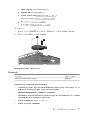
... off or in Hibernation, turn the computer on page 68) e. Disconnect all external devices connected to the base enclosure. 2. Remove the fan (2) from the computer. 4. Subwoofer Description Subwoofer (includes 2 mounting grommets) Spare part number 480471-001 Before removing the subwoofer, follow these...72) f. Shut down through the operating system. 2. Remove the following components: Component replacement procedures 97 Reverse this procedure to install the fan. Remove the battery (see Top cover on page 66) d. Speaker assembly (see System board on page 73) g. System board (...
... off or in Hibernation, turn the computer on page 68) e. Disconnect all external devices connected to the base enclosure. 2. Remove the fan (2) from the computer. 4. Subwoofer Description Subwoofer (includes 2 mounting grommets) Spare part number 480471-001 Before removing the subwoofer, follow these...72) f. Shut down through the operating system. 2. Remove the following components: Component replacement procedures 97 Reverse this procedure to install the fan. Remove the battery (see Top cover on page 66) d. Speaker assembly (see System board on page 73) g. System board (...
Service Guide
Page 119
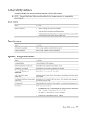
...disable LAN Power Saving. When enabled, saves power when models only) the computer is in DC mode. When enabled, the computer fan will always be supported by your computer. Main menu Select System information To do this Language Support Change the Setup Utility language. System... Configuration menu Select To do this section provide an overview of Setup Utility options. Fan Always On Enabled/disable Fan Always On. Security menu Select Administrator password Power-On Password To do this ● View and change the system time...
...disable LAN Power Saving. When enabled, saves power when models only) the computer is in DC mode. When enabled, the computer fan will always be supported by your computer. Main menu Select System information To do this Language Support Change the Setup Utility language. System... Configuration menu Select To do this section provide an overview of Setup Utility options. Fan Always On Enabled/disable Fan Always On. Security menu Select Administrator password Power-On Password To do this ● View and change the system time...
Service Guide
Page 139
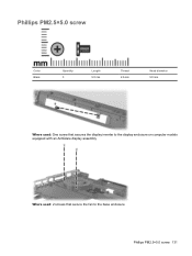
Phillips PM2.5×5.0 screw Color Black Quantity 3 Length 5.0 mm Thread 2.5 mm Head diameter 5.0 mm Where used: One screw that secures the display inverter to the display enclosure on computer models equipped with an AntiGlare display assembly Where used: 2 screws that secure the fan to the base enclosure Phillips PM2.5×5.0 screw 131
Phillips PM2.5×5.0 screw Color Black Quantity 3 Length 5.0 mm Thread 2.5 mm Head diameter 5.0 mm Where used: One screw that secures the display inverter to the display enclosure on computer models equipped with an AntiGlare display assembly Where used: 2 screws that secure the fan to the base enclosure Phillips PM2.5×5.0 screw 131
Service Guide
Page 177
... ExpressCard slot bezel, illustrated 31 external media cards, product description 5 external monitor port location 15 pin assignments 156 F f11 153 fan removal 96 spare part numbers 24, 38, 41, 96 fan always on 111 feet locations 51 spare part number 51 fingerprint reader 10, 108 fingerprint reader board removal 85 spare part...
... ExpressCard slot bezel, illustrated 31 external media cards, product description 5 external monitor port location 15 pin assignments 156 F f11 153 fan removal 96 spare part numbers 24, 38, 41, 96 fan always on 111 feet locations 51 spare part number 51 fingerprint reader 10, 108 fingerprint reader board removal 85 spare part...


