Service Guide
Page 6
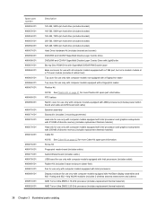
... Equipment guidelines 48 Unknown user password 49 Component replacement procedures 50 Service tag ...50 Computer feet ...51 Battery ...51 Webcam/microphone module 53 Optical drive ...54 Hard drive ...56 TV tuner module ...58 RTC battery ...60 WLAN module ...61 Memory module ...64 Switch cover ...66 Keyboard ...68 Bluetooth module ...71 Speaker assembly...
... Equipment guidelines 48 Unknown user password 49 Component replacement procedures 50 Service tag ...50 Computer feet ...51 Battery ...51 Webcam/microphone module 53 Optical drive ...54 Hard drive ...56 TV tuner module ...58 RTC battery ...60 WLAN module ...61 Memory module ...64 Switch cover ...66 Keyboard ...68 Bluetooth module ...71 Speaker assembly...
Service Guide
Page 8
... Universal Serial Bus ...159 10 Power cord set requirements Requirements for all countries or regions 160 Requirements for specific countries or regions 161 11 Recycling Battery ...162 Display ...162 Index ...168 viii
... Universal Serial Bus ...159 10 Power cord set requirements Requirements for all countries or regions 160 Requirements for specific countries or regions 161 11 Recycling Battery ...162 Display ...162 Index ...168 viii
Service Guide
Page 14
... √ Taps enabled as default √ √ √ Power 8-cell 2.55-Ah Li-ion battery √ √ requirements 6-cell 2.20-Ah Li-ion battery √ 90-W AC adapter with localized cable √ √ plug support (2-wire plug with ground pin...Vista Premium (32 bit) √ √ √ Windows Vista Ultimate (64 bit) √ √ √ Serviceability AC adapter √ √ √ Battery (system) √ √ √ Hard drives (2) √ √ √ Memory module √ √ √ Optical drive √ √ ...
... √ Taps enabled as default √ √ √ Power 8-cell 2.55-Ah Li-ion battery √ √ requirements 6-cell 2.20-Ah Li-ion battery √ 90-W AC adapter with localized cable √ √ plug support (2-wire plug with ground pin...Vista Premium (32 bit) √ √ √ Windows Vista Ultimate (64 bit) √ √ √ Serviceability AC adapter √ √ √ Battery (system) √ √ √ Hard drives (2) √ √ √ Memory module √ √ √ Optical drive √ √ ...
Service Guide
Page 21
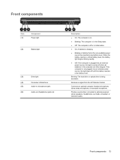
Receives a signal from the HP Remote Control. Blinking: The hard drive or optical drive is the only available power source has reached a low battery level. Front components 13 Front components Item (1) Component Power light (2) Battery light (3) Drive light (4) Consumer infrared lens (5) Audio-in (...state. ● Off: The computer is off when all batteries in Hibernation. ● On: A battery is charging. ● Blinking: A battery that is being accessed. When the battery reaches a critical battery level, the battery light begins blinking rapidly. ● Off: If the computer...
Receives a signal from the HP Remote Control. Blinking: The hard drive or optical drive is the only available power source has reached a low battery level. Front components 13 Front components Item (1) Component Power light (2) Battery light (3) Drive light (4) Consumer infrared lens (5) Audio-in (...state. ● Off: The computer is off when all batteries in Hibernation. ● On: A battery is charging. ● Blinking: A battery that is being accessed. When the battery reaches a critical battery level, the battery light begins blinking rapidly. ● Off: If the computer...
Service Guide
Page 24
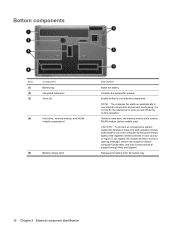
... airflow to cool internal components and prevent overheating. Bottom components Item (1) (2) (3) Component Battery bay Integrated subwoofer Vents (5) (4) Hard drive, memory module, and WLAN module compartment (5) Battery release latch Description Holds the battery. Contains the subwoofer speaker. Releases the battery from the battery bay. 16 Chapter 2 External component identification It is normal for use in the...
... airflow to cool internal components and prevent overheating. Bottom components Item (1) (2) (3) Component Battery bay Integrated subwoofer Vents (5) (4) Hard drive, memory module, and WLAN module compartment (5) Battery release latch Description Holds the battery. Contains the subwoofer speaker. Releases the battery from the battery bay. 16 Chapter 2 External component identification It is normal for use in the...
Service Guide
Page 34
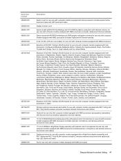
...160-GB, 5400-rpm 480453-001 120-GB, 5400-rpm 480452-001 Hard Drive Hardware Kit (not illustrated, includes bracket and screws) 480457-001 RTC battery 480468-001 Memory modules (667-MHz, PC2-6400, 1-DIMM): 2048-MB memory module 480382-001 1024-MB memory module 480381-001 512-MB memory module... 480380-001 Batteries: 8-cell, 73-Wh, 2.55-Ah Li-ion battery for use with all computer models 480385-001 6-cell, 47-Wh, 2.55-Ah Li-ion battery for use only with computer models equipped with 486766-001 AMD processors 26 ...
...160-GB, 5400-rpm 480453-001 120-GB, 5400-rpm 480452-001 Hard Drive Hardware Kit (not illustrated, includes bracket and screws) 480457-001 RTC battery 480468-001 Memory modules (667-MHz, PC2-6400, 1-DIMM): 2048-MB memory module 480382-001 1024-MB memory module 480381-001 512-MB memory module... 480380-001 Batteries: 8-cell, 73-Wh, 2.55-Ah Li-ion battery for use with all computer models 480385-001 6-cell, 47-Wh, 2.55-Ah Li-ion battery for use only with computer models equipped with 486766-001 AMD processors 26 ...
Service Guide
Page 45
...) 1024-MB memory module (667-MHz, PC2-6400, 1-DIMM) 2048-MB memory module (667-MHz, PC2-6400, 1-DIMM) 8-cell, 73-Wh, 2.55-Ah Li-ion battery for use with all computer models WXGA BrightView display panel for use only with computer models equipped with BrightView display assemblies (includes display panel cable...
...) 1024-MB memory module (667-MHz, PC2-6400, 1-DIMM) 2048-MB memory module (667-MHz, PC2-6400, 1-DIMM) 8-cell, 73-Wh, 2.55-Ah Li-ion battery for use with all computer models WXGA BrightView display panel for use only with computer models equipped with BrightView display assemblies (includes display panel cable...
Service Guide
Page 46
... models equipped with a fingerprint reader Plastics Kit NOTE: See Plastics Kit on page 32 for more Cable Kit spare part information. RTC battery Switch cover for use only with computer models equipped with AMD processors (includes power button board and cable and LED board and cable)...assembies and 802.11a/b/g and 802.11b/g WLAN modules (includes 2 wireless antenna transceivers and cables) AMD Turion Ultra ZM80 2.10-GHz processor (includes replacement thermal material) AMD Turion Ultra ZM82 2.20-GHz processor (includes replacement thermal material) 38 Chapter 3 Illustrated parts catalog
... models equipped with a fingerprint reader Plastics Kit NOTE: See Plastics Kit on page 32 for more Cable Kit spare part information. RTC battery Switch cover for use only with computer models equipped with AMD processors (includes power button board and cable and LED board and cable)...assembies and 802.11a/b/g and 802.11b/g WLAN modules (includes 2 wireless antenna transceivers and cables) AMD Turion Ultra ZM80 2.10-GHz processor (includes replacement thermal material) AMD Turion Ultra ZM82 2.20-GHz processor (includes replacement thermal material) 38 Chapter 3 Illustrated parts catalog
Service Guide
Page 49
... UMA graphics subsystem memory for use only with computer models equipped with AMD processors (includes replacement thermal material) 6-cell, 47-Wh, 2.55-Ah Li-ion battery for use only with computer models equipped with AMD processors Broadcom 4322 802.11a/b/g/n WLAN module for use only with computer models equipped with Intel...
... UMA graphics subsystem memory for use only with computer models equipped with AMD processors (includes replacement thermal material) 6-cell, 47-Wh, 2.55-Ah Li-ion battery for use only with computer models equipped with AMD processors Broadcom 4322 802.11a/b/g/n WLAN module for use only with computer models equipped with Intel...
Service Guide
Page 57
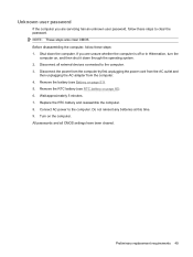
...Preliminary replacement requirements 49 Before disassembling the computer, follow these steps: 1. Disconnect all CMOS settings have been cleared. Do not reinsert any batteries at this time. 9. Shut down through the operating system. 2. Connect AC power to the computer. All passwords and all external devices ...connected to clear the password. Remove the RTC battery (see Battery on page 60). 6. Wait approximately 5 minutes. 7. If you are unsure whether the computer is off or in Hibernation, turn ...
...Preliminary replacement requirements 49 Before disassembling the computer, follow these steps: 1. Disconnect all CMOS settings have been cleared. Do not reinsert any batteries at this time. 9. Shut down through the operating system. 2. Connect AC power to the computer. All passwords and all external devices ...connected to clear the password. Remove the RTC battery (see Battery on page 60). 6. Wait approximately 5 minutes. 7. If you are unsure whether the computer is off or in Hibernation, turn ...
Service Guide
Page 59
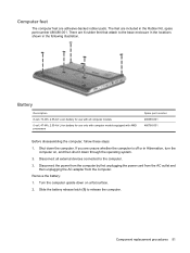
... by first unplugging the power cord from the AC outlet and then unplugging the AC adapter from the computer. Component replacement procedures 51 Remove the battery: 1. The feet are unsure whether the computer is off or in Hibernation, turn the computer on, and then shut it down on a flat surface. 2.... in the locations shown in the Rubber Kit, spare part number 480480-001. Disconnect all computer models 6-cell, 47-Wh, 2.55-Ah Li-ion battery for use only with computer models equipped with all external devices connected to release the computer. Shut down the computer. Slide the...
... by first unplugging the power cord from the AC outlet and then unplugging the AC adapter from the computer. Component replacement procedures 51 Remove the battery: 1. The feet are unsure whether the computer is off or in Hibernation, turn the computer on, and then shut it down on a flat surface. 2.... in the locations shown in the Rubber Kit, spare part number 480480-001. Disconnect all computer models 6-cell, 47-Wh, 2.55-Ah Li-ion battery for use only with computer models equipped with all external devices connected to release the computer. Shut down the computer. Slide the...
Service Guide
Page 60
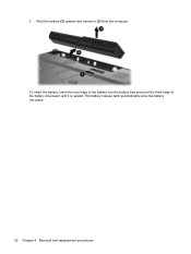
Pivot the battery (2) upward and remove it is seated. 3. The battery release latch automatically locks the battery into the battery bay and pivot the front edge of the battery into place. 52 Chapter 4 Removal and replacement procedures To insert the battery, insert the rear edge of the battery downward until it (3) from the computer.
Pivot the battery (2) upward and remove it is seated. 3. The battery release latch automatically locks the battery into the battery bay and pivot the front edge of the battery into place. 52 Chapter 4 Removal and replacement procedures To insert the battery, insert the rear edge of the battery downward until it (3) from the computer.
Service Guide
Page 61
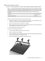
For information on replacing the display assembly and other display assembly internal components, see Battery on page 73. Shut down through the operating system. 2. Release the display bezel top edge (3) from the display enclosure. 4. Description Webcam/microphone ... 1. Disconnect all external devices connected to replace the webcam/microphone module. Webcam/microphone module NOTE: This section applies only to be removed. Remove the battery (see Display assembly on page 51). Open the computer as far as possible. 3. Flex the inside edges of the top edge (1) and the ...
For information on replacing the display assembly and other display assembly internal components, see Battery on page 73. Shut down through the operating system. 2. Release the display bezel top edge (3) from the display enclosure. 4. Description Webcam/microphone ... 1. Disconnect all external devices connected to replace the webcam/microphone module. Webcam/microphone module NOTE: This section applies only to be removed. Remove the battery (see Display assembly on page 51). Open the computer as far as possible. 3. Flex the inside edges of the top edge (1) and the ...
Service Guide
Page 62
..., follow these steps: 1. Disconnect all external devices connected to the computer. 3. Disconnect the webcam/microphone module cable (2) from the webcam/microphone module. 7. Remove the battery (see Battery on , and then shut it down the computer. Remove the webcam/microphone module. Description Blu-ray Disc ROM Drive with SuperMulti DVD±R/RW Double...
..., follow these steps: 1. Disconnect all external devices connected to the computer. 3. Disconnect the webcam/microphone module cable (2) from the webcam/microphone module. 7. Remove the battery (see Battery on , and then shut it down the computer. Remove the webcam/microphone module. Description Blu-ray Disc ROM Drive with SuperMulti DVD±R/RW Double...
Service Guide
Page 64
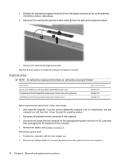
... then unplugging the AC adapter from the computer. 4. The accessory cover is off or in the Plastics Kit, spare part number 480467-001. 4. Remove the battery (see Battery on , and then shut it up and forward, and then remove the cover (3). Lift the rear edge of the accessory cover (2), swing it down...
... then unplugging the AC adapter from the computer. 4. The accessory cover is off or in the Plastics Kit, spare part number 480467-001. 4. Remove the battery (see Battery on , and then shut it up and forward, and then remove the cover (3). Lift the rear edge of the accessory cover (2), swing it down...
Service Guide
Page 66
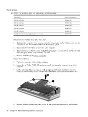
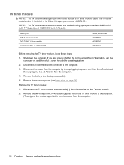
...the AC Adapter from the terminal on , and then shut it down the computer. Remove the TV tuner module: 1. Remove the accessory cover (see Battery on page 56). TV tuner module NOTE: The TV tuner module spare part kits do not include a TV tuner module cable. Remove the two ... and 482900-002 (with PAL jack). Disconnect the TV tuner module antenna cable (1) from the computer. 4. Shut down through the operating system. 2. Remove the battery (see Hard drive on page 51). 5. Description DVB-T TV tuner module DVD-T/ANG TV tuner module NTSC/ATSC/ANG TV tuner module Spare part number...
...the AC Adapter from the terminal on , and then shut it down the computer. Remove the TV tuner module: 1. Remove the accessory cover (see Battery on page 56). TV tuner module NOTE: The TV tuner module spare part kits do not include a TV tuner module cable. Remove the two ... and 482900-002 (with PAL jack). Disconnect the TV tuner module antenna cable (1) from the computer. 4. Shut down through the operating system. 2. Remove the battery (see Hard drive on page 51). 5. Description DVB-T TV tuner module DVD-T/ANG TV tuner module NTSC/ATSC/ANG TV tuner module Spare part number...
Service Guide
Page 68
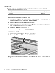
... minutes causes all external devices connected to the computer. 3. Disconnect all passwords and CMOS settings to install the RTC battery. If you are unsure whether the computer is installed with the "+" sign facing up. 60 Chapter 4 Removal and replacement procedures Description ...RTC battery Spare part number 480468-001 Before removing the RTC battery, follow these steps: 1. Disconnect the power from the computer by first unplugging the power cord from the ...
... minutes causes all external devices connected to the computer. 3. Disconnect all passwords and CMOS settings to install the RTC battery. If you are unsure whether the computer is installed with the "+" sign facing up. 60 Chapter 4 Removal and replacement procedures Description ...RTC battery Spare part number 480468-001 Before removing the RTC battery, follow these steps: 1. Disconnect the power from the computer by first unplugging the power cord from the ...
Service Guide
Page 71
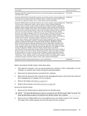
... the two Phillips PM2.0×4.0 screws (2) that secure the WLAN module to the WLAN module "Aux" terminal. 2. Remove the battery (see Hard drive on page 51). 5. Remove the accessory cover (see Battery on page 56). Description Spare part number Broadcom 4322 802.11a/b/g/n WLAN module for use only with computer models equipped...
... the two Phillips PM2.0×4.0 screws (2) that secure the WLAN module to the WLAN module "Aux" terminal. 2. Remove the battery (see Hard drive on page 51). 5. Remove the accessory cover (see Battery on page 56). Description Spare part number Broadcom 4322 802.11a/b/g/n WLAN module for use only with computer models equipped...
Service Guide
Page 72
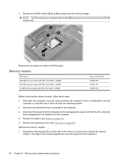
... procedures Reverse this procedure to prevent incorrect insertion into the WLAN module slot. Remove the accessory cover (see Battery on page 56). Remove the memory module: 1. Shut down through the operating system. 2. Remove the battery (see Hard drive on page 51). 5. NOTE: WLAN modules are unsure whether the computer is off or...
... procedures Reverse this procedure to prevent incorrect insertion into the WLAN module slot. Remove the accessory cover (see Battery on page 56). Remove the memory module: 1. Shut down through the operating system. 2. Remove the battery (see Hard drive on page 51). 5. NOTE: WLAN modules are unsure whether the computer is off or...
Service Guide
Page 74
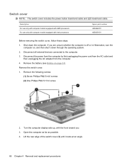
... as possible. 4. Lift the rear edge of the switch cover (1) until it down the computer. Disconnect all external devices connected to the computer. 3. Remove the battery (see Battery on , and then shut it rests at an angle. 66 Chapter 4 Removal and replacement procedures Shut down through the operating system. 2. If you . 3. Remove...
... as possible. 4. Lift the rear edge of the switch cover (1) until it down the computer. Disconnect all external devices connected to the computer. 3. Remove the battery (see Battery on , and then shut it rests at an angle. 66 Chapter 4 Removal and replacement procedures Shut down through the operating system. 2. If you . 3. Remove...


