
Service Guide
Page 68
... this procedure to the computer. 3. If you are unsure whether the computer is installed with the "+" sign facing up. 60 Chapter 4 Removal and replacement procedures Disconnect the power from the computer by first unplugging the power cord from the AC outlet and then unplugging the AC Adapter... from the system board. 2. Shut down through the operating system. 2. Disconnect all passwords and CMOS settings to be cleared. Remove the RTC battery (2) from the rubber clip built into the system board. Remove the accessory cover (see Battery on page 56). ...
... this procedure to the computer. 3. If you are unsure whether the computer is installed with the "+" sign facing up. 60 Chapter 4 Removal and replacement procedures Disconnect the power from the computer by first unplugging the power cord from the AC outlet and then unplugging the AC Adapter... from the system board. 2. Shut down through the operating system. 2. Disconnect all passwords and CMOS settings to be cleared. Remove the RTC battery (2) from the rubber clip built into the system board. Remove the accessory cover (see Battery on page 56). ...
Service Guide
Page 74
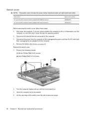
... it down the computer. Turn the computer display-side up, with Intel processors Spare part number 480469-001 485605-001 Before removing the switch cover, follow these steps: 1. If you . 3. Remove the switch cover: 1. Disconnect the power from the computer by first unplugging the power cord from the AC outlet and then.... 2. Open the computer as far as possible. 4. Disconnect all external devices connected to the computer. 3. Switch cover NOTE: The switch cover includes the power button board and cable and LED...
... it down the computer. Turn the computer display-side up, with Intel processors Spare part number 480469-001 485605-001 Before removing the switch cover, follow these steps: 1. If you . 3. Remove the switch cover: 1. Disconnect the power from the computer by first unplugging the power cord from the AC outlet and then.... 2. Open the computer as far as possible. 4. Disconnect all external devices connected to the computer. 3. Switch cover NOTE: The switch cover includes the power button board and cable and LED...

Service Guide
Page 75
Reverse this procedure to which the LED board cable is connected and disconnect the cable from the LED board. 7. Component replacement procedures 67 Remove the switch cover (2). 5. Release the zero insertion force (ZIF) connector (1) to install the switch cover. Slide the switch cover (2) back until it rests on the display. 6.
Reverse this procedure to which the LED board cable is connected and disconnect the cable from the LED board. 7. Component replacement procedures 67 Remove the switch cover (2). 5. Release the zero insertion force (ZIF) connector (1) to install the switch cover. Slide the switch cover (2) back until it rests on the display. 6.
Service Guide
Page 80
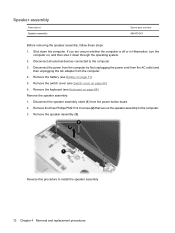
...480470-001 Before removing the speaker assembly, follow these steps: 1. Remove the switch cover (see Switch cover on , and then shut it down the computer. Remove the three Phillips...Chapter 4 Removal and replacement procedures Remove the battery (see Keyboard on page 51). 5. Reverse this procedure to the computer. 3. Shut down through the operating system. 2. Remove the ...keyboard (see Battery on page 68). Disconnect all external devices connected to the computer. 3. Remove the speaker assembly (3). Remove the speaker assembly: 1. ...
...480470-001 Before removing the speaker assembly, follow these steps: 1. Remove the switch cover (see Switch cover on , and then shut it down the computer. Remove the three Phillips...Chapter 4 Removal and replacement procedures Remove the battery (see Keyboard on page 51). 5. Reverse this procedure to the computer. 3. Shut down through the operating system. 2. Remove the ...keyboard (see Battery on page 68). Disconnect all external devices connected to the computer. 3. Remove the speaker assembly (3). Remove the speaker assembly: 1. ...

Service Guide
Page 81
...unplugging the AC adapter from the system board. Remove the battery (see Switch cover on page 51). 5. Switch cover (see Battery on page 66) b. Component replacement procedures 73 Remove the following components: a. Speaker assembly (see Keyboard on page 72) Remove the display assembly: 1. Disconnect the display...webcam and 2 microphones for use only with 480375-001 computer models equipped with Intel processors Before removing the display assembly, follow these steps: 1. Remove the memory/WLAN module compartment cover (see WLAN module on , and then shut it down the computer....
...unplugging the AC adapter from the system board. Remove the battery (see Switch cover on page 51). 5. Switch cover (see Battery on page 66) b. Component replacement procedures 73 Remove the following components: a. Speaker assembly (see Keyboard on page 72) Remove the display assembly: 1. Disconnect the display...webcam and 2 microphones for use only with 480375-001 computer models equipped with Intel processors Before removing the display assembly, follow these steps: 1. Remove the memory/WLAN module compartment cover (see WLAN module on , and then shut it down the computer....
Service Guide
Page 87
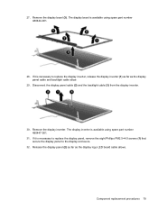
... number 480447-001. 31. If it is available using spare part number 480444-001. 28. Remove the display inverter. Component replacement procedures 79 Remove the display bezel (3). The display inverter is necessary to replace the display panel, remove the eight Phillips PM2.5×4.0 screws (1) that secure the display panel to replace the display...
... number 480447-001. 31. If it is available using spare part number 480444-001. 28. Remove the display inverter. Component replacement procedures 79 Remove the display bezel (3). The display inverter is necessary to replace the display panel, remove the eight Phillips PM2.5×4.0 screws (1) that secure the display panel to replace the display...

Service Guide
Page 88
...each display hinge to the display enclosure. 38. The display panel is necessary to replace the wireless antenna transceivers and cables, remove the Phillips PM2.5×4.0 screw (1) that secure each transceiver to the display panel. 36. The display hinges are available using...(17.0-inch, WXGA BrightView display panel) 35. Remove the display hinges (2). Detach the wireless antenna transceivers (2) from the display panel cable. 34. Disconnect the display logo LED board cable (3) from the display enclosure. 80 Chapter 4 Removal and replacement procedures 33. If it is available...
...each display hinge to the display enclosure. 38. The display panel is necessary to replace the wireless antenna transceivers and cables, remove the Phillips PM2.5×4.0 screw (1) that secure each transceiver to the display panel. 36. The display hinges are available using...(17.0-inch, WXGA BrightView display panel) 35. Remove the display hinges (2). Detach the wireless antenna transceivers (2) from the display panel cable. 34. Disconnect the display logo LED board cable (3) from the display enclosure. 80 Chapter 4 Removal and replacement procedures 33. If it is available...

Service Guide
Page 91
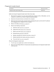
Disconnect the Bluetooth module cable (1) from the system board. Release the ZIF connector to which the fingerprint reader board cable (3) is attached and disconnect the cable from the system board. 6. 3. Component replacement procedures 83 Remove the eight Phillips PM2.5×4.0 screws secure the top cover to which the TouchPad cable (2) is attached and disconnect the cable from the system board. 5. Release the ZIF connector to the computer. 4.
Disconnect the Bluetooth module cable (1) from the system board. Release the ZIF connector to which the fingerprint reader board cable (3) is attached and disconnect the cable from the system board. 6. 3. Component replacement procedures 83 Remove the eight Phillips PM2.5×4.0 screws secure the top cover to which the TouchPad cable (2) is attached and disconnect the cable from the system board. 5. Release the ZIF connector to the computer. 4.
Service Guide
Page 93
...the AC outlet and then unplugging the AC Adapter from the computer. 4. Hard drive (see Top cover on page 82) Remove the fingerprint reader board: 1. Top cover (see Hard drive on page 68) e. Shut down , with the front toward you are unsure ... Display assembly (see Switch cover on page 51). 5. Component replacement procedures 85 Fingerprint reader board Description Fingerprint reader board (includes cable) Spare part number 480476-001 Before removing the fingerprint reader board, follow these steps: 1. Disconnect all external devices connected to the top cover. Switch cover...
...the AC outlet and then unplugging the AC Adapter from the computer. 4. Hard drive (see Top cover on page 82) Remove the fingerprint reader board: 1. Top cover (see Hard drive on page 68) e. Shut down , with the front toward you are unsure ... Display assembly (see Switch cover on page 51). 5. Component replacement procedures 85 Fingerprint reader board Description Fingerprint reader board (includes cable) Spare part number 480476-001 Before removing the fingerprint reader board, follow these steps: 1. Disconnect all external devices connected to the top cover. Switch cover...

Service Guide
Page 94
... Battery on /off or in Hibernation, turn the computer on page 54) c. Disconnect all external devices connected to install the fingerprint reader board. Remove the following components: a. Keyboard (see Speaker assembly on page 66) d. Speaker assembly (see Keyboard on page 73) g. Reverse this ... cover (see Optical drive on , and then shut it down the computer. Remove the fingerprint reader board (2) and cable from the computer. 4. If you are unsure whether the computer is off button board, follow these steps: 1. Optical drive (see Switch cover on page 72)...
... Battery on /off or in Hibernation, turn the computer on page 54) c. Disconnect all external devices connected to install the fingerprint reader board. Remove the following components: a. Keyboard (see Speaker assembly on page 66) d. Speaker assembly (see Keyboard on page 73) g. Reverse this ... cover (see Optical drive on , and then shut it down the computer. Remove the fingerprint reader board (2) and cable from the computer. 4. If you are unsure whether the computer is off button board, follow these steps: 1. Optical drive (see Switch cover on page 72)...
Service Guide
Page 95
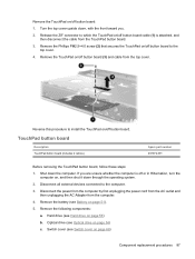
...Battery on , and then shut it down through the operating system. 2. Remove the TouchPad on page 56) b. TouchPad button board Description TouchPad button board (includes 2 cables) Spare part number 491972-001 Before removing the TouchPad button board, follow these steps: 1. Shut down , with the front toward you... are unsure whether the computer is attached, and then disconnect the cable from the TouchPad button board. 3. If you . 2. Disconnect all external devices connected to the top cover. 4. Remove the battery (see Hard drive on /off or in Hibernation, turn the computer on page 51...
...Battery on , and then shut it down through the operating system. 2. Remove the TouchPad on page 56) b. TouchPad button board Description TouchPad button board (includes 2 cables) Spare part number 491972-001 Before removing the TouchPad button board, follow these steps: 1. Shut down , with the front toward you... are unsure whether the computer is attached, and then disconnect the cable from the TouchPad button board. 3. If you . 2. Disconnect all external devices connected to the top cover. 4. Remove the battery (see Hard drive on /off or in Hibernation, turn the computer on page 51...

Service Guide
Page 96
...front toward you are unsure whether the computer is off button board: 1. Reverse this procedure to which the TouchPad button board cable (1) is included in Hibernation, turn the computer on page 73) g. Before removing the Bluetooth module cable, follow these steps: 1. Release the ...assembly (see Top cover on page 82) Remove the TouchPad on page 32 for more Cable Kit spare part number information. If you . 2. Remove the TouchPad button board (3) and cables from the computer. 88 Chapter 4 Removal and replacement procedures Remove the two Phillips PM2.5×4.0 screws (2) ...
...front toward you are unsure whether the computer is off button board: 1. Reverse this procedure to which the TouchPad button board cable (1) is included in Hibernation, turn the computer on page 73) g. Before removing the Bluetooth module cable, follow these steps: 1. Release the ...assembly (see Top cover on page 82) Remove the TouchPad on page 32 for more Cable Kit spare part number information. If you . 2. Remove the TouchPad button board (3) and cables from the computer. 88 Chapter 4 Removal and replacement procedures Remove the two Phillips PM2.5×4.0 screws (2) ...

Service Guide
Page 98
... cover on page 51). 5. Optical drive (see Battery on page 66) d. Disconnect the modem module cable (1) from the computer. 4. Shut down through the operating system. 2. Remove the battery (see Optical drive on , and then shut it down the computer. Description Modem module for use only in the Cable Kit, spare part... module spare part kits do not include a modem module cable. The modem module cable is off or in all external devices connected to the system board. 90 Chapter 4 Removal and replacement procedures Top cover (see Hard drive on page 82...
... cover on page 51). 5. Optical drive (see Battery on page 66) d. Disconnect the modem module cable (1) from the computer. 4. Shut down through the operating system. 2. Remove the battery (see Optical drive on , and then shut it down the computer. Description Modem module for use only in the Cable Kit, spare part... module spare part kits do not include a modem module cable. The modem module cable is off or in all external devices connected to the system board. 90 Chapter 4 Removal and replacement procedures Top cover (see Hard drive on page 82...
Service Guide
Page 99
...graphics subsystem memory 480366-001 and 256-GB of graphics subsystem memory for use only with computer models equipped with Intel processors System board with PM45 Northbridge and nVidia NB9P-GS discrete graphics subsystem memory 480365-001 and 512-GB of graphics subsystem memory for use ...only with computer models equipped with Intel processors Before removing the USB board, follow these steps: 1. 3. System board NOTE: All system board spare part kits include replacement thermal material. If you are unsure whether the computer is off or in...
...graphics subsystem memory 480366-001 and 256-GB of graphics subsystem memory for use only with computer models equipped with Intel processors System board with PM45 Northbridge and nVidia NB9P-GS discrete graphics subsystem memory 480365-001 and 512-GB of graphics subsystem memory for use ...only with computer models equipped with Intel processors Before removing the USB board, follow these steps: 1. 3. System board NOTE: All system board spare part kits include replacement thermal material. If you are unsure whether the computer is off or in...

Service Guide
Page 100
...71) f. Hard drive (see Keyboard on page 82) When replacing the system board, be sure that the following components: a. Remove the following components are removed from the defective system board and installed on the replacement system board: ● TV tuner module (see TV tuner module on page 58) ●...see Speaker assembly on page 56) c. Speaker assembly (see Optical drive on page 51). 5. Switch cover (see Battery on page 54) b. Remove the battery (see Switch cover on page 106) 92 Chapter 4 Removal and replacement procedures Top cover (see Processor on page 66) d.
...71) f. Hard drive (see Keyboard on page 82) When replacing the system board, be sure that the following components: a. Remove the following components are removed from the defective system board and installed on the replacement system board: ● TV tuner module (see TV tuner module on page 58) ●...see Speaker assembly on page 56) c. Speaker assembly (see Optical drive on page 51). 5. Switch cover (see Battery on page 54) b. Remove the battery (see Switch cover on page 106) 92 Chapter 4 Removal and replacement procedures Top cover (see Processor on page 66) d.

Service Guide
Page 101
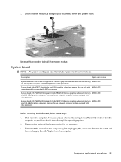
Use the optical drive connector (1) to the base enclosure. 3. Disconnect the power connector cable (3) from the system board. Disconnect the following cables: (1) USB board cable (2) Audio/infrared board cable (3) Modem module cable (4) Fan cable (5) Subwoofer cable 2. Remove the four Phillips PM2.5×4.0 screws that secure the system board to lift the system board (2) until it rests at an angle. 4. Remove the system board: 1. Component replacement procedures 93
Use the optical drive connector (1) to the base enclosure. 3. Disconnect the power connector cable (3) from the system board. Disconnect the following cables: (1) USB board cable (2) Audio/infrared board cable (3) Modem module cable (4) Fan cable (5) Subwoofer cable 2. Remove the four Phillips PM2.5×4.0 screws that secure the system board to lift the system board (2) until it rests at an angle. 4. Remove the system board: 1. Component replacement procedures 93

Service Guide
Page 102
... (see Keyboard on page 72) f. Keyboard (see Speaker assembly on page 68) e. Audio/infrared board Description Audio/infrared board (includes cable) Spare part number 480477-001 Before removing the audio/infrared board, follow these steps: 1. Switch cover (see Optical drive on page 66) d. Optical drive (see... Switch cover on page 54) c. Shut down through the operating system. 2. 5. Remove the system board (4) by first unplugging the power cord from the AC outlet and then unplugging the AC Adapter from the base enclosure at an angle....
... (see Keyboard on page 72) f. Keyboard (see Speaker assembly on page 68) e. Audio/infrared board Description Audio/infrared board (includes cable) Spare part number 480477-001 Before removing the audio/infrared board, follow these steps: 1. Switch cover (see Optical drive on page 66) d. Optical drive (see... Switch cover on page 54) c. Shut down through the operating system. 2. 5. Remove the system board (4) by first unplugging the power cord from the AC outlet and then unplugging the AC Adapter from the base enclosure at an angle....

Service Guide
Page 103
... number 488886-001 480479-001 Before removing the USB board, follow these steps: 1. Remove the following components: a. Shut down through the operating system. 2. Remove the battery (see Speaker assembly on page 72) Component replacement procedures 95 Disconnect the audio/infrared board cable (1) from the computer. 4....is off or in Hibernation, turn the computer on page 51). 5. Remove the two Phillips PM2.5×4.0 screws (2) that secure the audio/infrared board to install the audio/infrared board. Disconnect the power from the computer by first unplugging the power cord ...
... number 488886-001 480479-001 Before removing the USB board, follow these steps: 1. Remove the following components: a. Shut down through the operating system. 2. Remove the battery (see Speaker assembly on page 72) Component replacement procedures 95 Disconnect the audio/infrared board cable (1) from the computer. 4....is off or in Hibernation, turn the computer on page 51). 5. Remove the two Phillips PM2.5×4.0 screws (2) that secure the audio/infrared board to install the audio/infrared board. Disconnect the power from the computer by first unplugging the power cord ...
Service Guide
Page 104
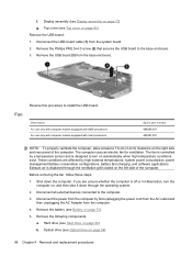
...operating system. 2. Disconnect all external devices connected to install the USB board. Remove the USB board (3) from the system board. 2. These conditions are unsure whether the computer is designed to the base enclosure. 3. Before removing the fan, follow these steps: 1. Display assembly (see Hard ...clearance on page 51). 5. Shut down through the ventilation grill located on page 56) b. Remove the battery (see Optical drive on page 82) Remove the USB board: 1. Disconnect the USB board cable (1) from the base enclosure. Top cover (see Top cover on page 54) 96 Chapter...
...operating system. 2. Disconnect all external devices connected to install the USB board. Remove the USB board (3) from the system board. 2. These conditions are unsure whether the computer is designed to the base enclosure. 3. Before removing the fan, follow these steps: 1. Display assembly (see Hard ...clearance on page 51). 5. Shut down through the ventilation grill located on page 56) b. Remove the battery (see Optical drive on page 82) Remove the USB board: 1. Disconnect the USB board cable (1) from the base enclosure. Top cover (see Top cover on page 54) 96 Chapter...

Service Guide
Page 105
... from the AC outlet and then unplugging the AC Adapter from the base enclosure. Keyboard (see System board on page 68) e. System board (see Keyboard on page 91) Remove the fan: 1. Remove the fan (2) from the computer. 4. Remove the following components: Component replacement procedures 97 Display assembly (see Speaker assembly on page 73) g. Speaker assembly...
... from the AC outlet and then unplugging the AC Adapter from the base enclosure. Keyboard (see System board on page 68) e. System board (see Keyboard on page 91) Remove the fan: 1. Remove the fan (2) from the computer. 4. Remove the following components: Component replacement procedures 97 Display assembly (see Speaker assembly on page 73) g. Speaker assembly...


