
HP Printers - Supported Citrix Presentation Server environments
Page 13
... client, the UPD PCL driver defaults to provide all printer configurations and user settings from the client. The difference between the Citrix and HP UPDs The Citrix UPD for Citrix Presentation Server 4.0, 4.5, or XenApp™ 5.0 works well for autocreated client printers. The Citrix UPD ... if the client's printer is a limitation of the client printers from the client printer, such as print on the client for features manually, then set the tray configuration, duplexer, and hard disk settings. The autocreated printers using the Citrix UPD for autocreated printers, it cannot...
... client, the UPD PCL driver defaults to provide all printer configurations and user settings from the client. The difference between the Citrix and HP UPDs The Citrix UPD for Citrix Presentation Server 4.0, 4.5, or XenApp™ 5.0 works well for autocreated client printers. The Citrix UPD ... if the client's printer is a limitation of the client printers from the client printer, such as print on the client for features manually, then set the tray configuration, duplexer, and hard disk settings. The autocreated printers using the Citrix UPD for autocreated printers, it cannot...
HP Printers - Supported Citrix Presentation Server environments
Page 23
...\CurrentControlSet\Control\Print\Environments\Windows NT x86\Drivers\Version3\ hive. Driver settings, such as version 61.081.xxx.xx or the latest HP Universal Print Driver, has a fix for features manually, then set the tray 23 Version 1.0.2.31 and newer has the fix. Client driver settings lost during autocreation. The server must...
...\CurrentControlSet\Control\Print\Environments\Windows NT x86\Drivers\Version3\ hive. Driver settings, such as version 61.081.xxx.xx or the latest HP Universal Print Driver, has a fix for features manually, then set the tray 23 Version 1.0.2.31 and newer has the fix. Client driver settings lost during autocreation. The server must...
Service Manual
Page 2
... translated into another language without notice. WARNING The procedures described in this manual are to death or injury may be performed by copyright. Graells, 501 08190 Sant Cugat del Vallès Spain HP internal order number C4699Ć90000 Second edition, March 1996 Printed in ...the enclosure. Electrostatic Discharge Refer to performing any kind with the furnishing, performance, or use of this manual, for precautions you do not take to...
... translated into another language without notice. WARNING The procedures described in this manual are to death or injury may be performed by copyright. Graells, 501 08190 Sant Cugat del Vallès Spain HP internal order number C4699Ć90000 Second edition, March 1996 Printed in ...the enclosure. Electrostatic Discharge Refer to performing any kind with the furnishing, performance, or use of this manual, for precautions you do not take to...
Service Manual
Page 4
... by these plotters, refer to the HP DesignJet 330 and 350C. ii Using this Manual C4699Ć90000 Using this Manual Purpose This manual contains information necessary to test, calibrate and service: D HP DesignJet 230 plotters (models C4694A and C4695A) D HP DesignJet 250C plotters (models C3190A and C3191A) D HP DesignJet 330 plotters (models C4701A and C4702A) D HP DesignJet 350C plotters (models C4699A and C4700A...
... by these plotters, refer to the HP DesignJet 330 and 350C. ii Using this Manual C4699Ć90000 Using this Manual Purpose This manual contains information necessary to test, calibrate and service: D HP DesignJet 230 plotters (models C4694A and C4695A) D HP DesignJet 250C plotters (models C3190A and C3191A) D HP DesignJet 330 plotters (models C4701A and C4702A) D HP DesignJet 350C plotters (models C4699A and C4700A...
Service Manual
Page 5
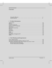
Contents Using this Manual ii Safety Symbols x 1 Product Information Applications 1Ć2 Drivers 1Ć2 Graphic Languages 1Ć2 DeviceĆControl Languages 1Ć2 Interfaces 1Ć3 Network Connections 1Ć3 Memory 1Ć3 Accuracy 1Ć3 Resolution 1Ć4 Legs 1Ć4 RollĆfeed 1Ć4 Upgrading a DesignJet 330 1Ć4 Media 1Ć4 2 Site Planning and Requirements Power Requirements 2Ć2 Choosing an...
Contents Using this Manual ii Safety Symbols x 1 Product Information Applications 1Ć2 Drivers 1Ć2 Graphic Languages 1Ć2 DeviceĆControl Languages 1Ć2 Interfaces 1Ć3 Network Connections 1Ć3 Memory 1Ć3 Accuracy 1Ć3 Resolution 1Ć4 Legs 1Ć4 RollĆfeed 1Ć4 Upgrading a DesignJet 330 1Ć4 Media 1Ć4 2 Site Planning and Requirements Power Requirements 2Ć2 Choosing an...
Service Manual
Page 7
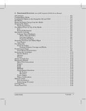
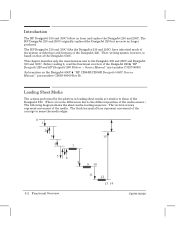
5 Functional Overview (more ' HP DesignJet 200/220 Service Manual) Introduction 5Ć2 Loading Sheet Media 5Ć2 Loading Roll Media on the DesignJet 330 and 350C 5Ć4 Roll Media 5Ć5 Removing Static Charge from the Media 5Ć5 Gripping the Media 5Ć5 PinchĆArm Sensor 5Ć5 Providing a Force ...
5 Functional Overview (more ' HP DesignJet 200/220 Service Manual) Introduction 5Ć2 Loading Sheet Media 5Ć2 Loading Roll Media on the DesignJet 330 and 350C 5Ć4 Roll Media 5Ć5 Removing Static Charge from the Media 5Ć5 Gripping the Media 5Ć5 PinchĆArm Sensor 5Ć5 Providing a Force ...
Service Manual
Page 12
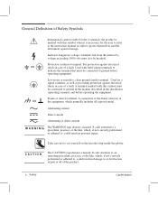
...wiring terminals to indicate the terminal that must be connected to protect themselves and the instrument against electrical shock in the installation (operating) manual, and before operating equipment. C A U T I ĂNĂG The WARNING sign denotes a hazard. General Definition of Safety Symbols OR ...OR International caution symbol (refer to manual): the product is necessary for a signal common, as well as providing protection against damage. Take care not to ground in the manner ...
...wiring terminals to indicate the terminal that must be connected to protect themselves and the instrument against electrical shock in the installation (operating) manual, and before operating equipment. C A U T I ĂNĂG The WARNING sign denotes a hazard. General Definition of Safety Symbols OR ...OR International caution symbol (refer to manual): the product is necessary for a signal common, as well as providing protection against damage. Take care not to ground in the manner ...
Service Manual
Page 20
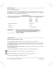
...262;C) Interface A short cable (less than 2 meters or 6.6 feet) for the parallel interface. (Interface descriptions ' Service Manual, chapter 5, w Input/Output Interfaces.) 230 250C (Pin specifications ' User's Guide, chapter 5, w Interface specifications.) 330 350C (Pin specifications ' User's Guide, chapter 10...power supplies and do not require a voltage selector or switch settings prior to use. Power Requirements HP DesignJet 230 and 330 and HP DesignJet 250C and 350C plotters have a protective earth (ground) terminal. Parallel (BiĆTronics/Centronics) Interface...
...262;C) Interface A short cable (less than 2 meters or 6.6 feet) for the parallel interface. (Interface descriptions ' Service Manual, chapter 5, w Input/Output Interfaces.) 230 250C (Pin specifications ' User's Guide, chapter 5, w Interface specifications.) 330 350C (Pin specifications ' User's Guide, chapter 10...power supplies and do not require a voltage selector or switch settings prior to use. Power Requirements HP DesignJet 230 and 330 and HP DesignJet 250C and 350C plotters have a protective earth (ground) terminal. Parallel (BiĆTronics/Centronics) Interface...
Service Manual
Page 44
... inherited much of the system architecture and features of the DesignJet 220 ' HP DesignJet 220 and HP DesignJet 200 Plotters - Their writing system, however, is based on the DesignJet 650C ' HP C2858B/C2859B DesignJet 650C Service Manual," part number C2858Ć90000 Rev B). The HP DesignJet 230 and 250C originally replaced the DesignJet 220 but are some differences due to those of the...
... inherited much of the system architecture and features of the DesignJet 220 ' HP DesignJet 220 and HP DesignJet 200 Plotters - Their writing system, however, is based on the DesignJet 650C ' HP C2858B/C2859B DesignJet 650C Service Manual," part number C2858Ć90000 Rev B). The HP DesignJet 230 and 250C originally replaced the DesignJet 220 but are some differences due to those of the...
Service Manual
Page 47
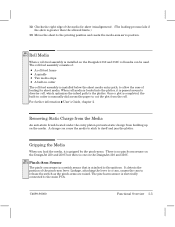
... loaded into the plotter, it is gripped by the pinchĆarms. There is no pinchĆarm sensor on the DesignJet 230 and 250C but there is one on the DesignJet 330 and 350C. 330 350C PinchĆArm Sensor The pinchĆarm sensor is a switch sensor that is passed around... and resets the mediaĆaxis servo position. 330 350C Roll Media When a rollĆfeed assembly is manually slid across the paper to cut the plot from building up on the DesignJet 330 and 350C roll media can cause the media to stick to the main PCA. 12 Checks the right...
... loaded into the plotter, it is gripped by the pinchĆarms. There is no pinchĆarm sensor on the DesignJet 230 and 250C but there is one on the DesignJet 330 and 350C. 330 350C PinchĆArm Sensor The pinchĆarm sensor is a switch sensor that is passed around... and resets the mediaĆaxis servo position. 330 350C Roll Media When a rollĆfeed assembly is manually slid across the paper to cut the plot from building up on the DesignJet 330 and 350C roll media can cause the media to stick to the main PCA. 12 Checks the right...
Service Manual
Page 53
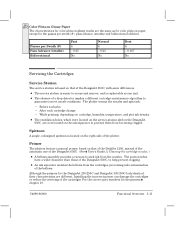
..., are now located on the ink separator to suck ink from the nozzles. Primer The plotters feature a manual primer, based on that of the DesignJet 650C, with some differences. Installing the incorrect primer can damage the cartridges or reduce the servicing of a drop detector ... bellows from becoming clogged. After each plot. - C4699Ć90000 Functional Overview 5Ć11 For the correct part numbers for the DesignJet 230/250C and DesignJet 330/350C look identical, their characteristics are different. Although the primers for the primers ' chapter 10. D The absence of the ...
..., are now located on the ink separator to suck ink from the nozzles. Primer The plotters feature a manual primer, based on that of the DesignJet 650C, with some differences. Installing the incorrect primer can damage the cartridges or reduce the servicing of a drop detector ... bellows from becoming clogged. After each plot. - C4699Ć90000 Functional Overview 5Ć11 For the correct part numbers for the DesignJet 230/250C and DesignJet 330/350C look identical, their characteristics are different. Although the primers for the primers ' chapter 10. D The absence of the ...

Service Manual
Page 90
... roller. slide the overdrive roller horizontally to the right until it has completely cleared the left to the right until the overdrive clutch can be manually rotated forward only. 4 While flexing the media separator upwards, ... ... Removing the Overdrive Roller 1 Remove the primer ' page 6Ć27. 2 Remove the service station ' page 6Ć...
... roller. slide the overdrive roller horizontally to the right until it has completely cleared the left to the right until the overdrive clutch can be manually rotated forward only. 4 While flexing the media separator upwards, ... ... Removing the Overdrive Roller 1 Remove the primer ' page 6Ć27. 2 Remove the service station ' page 6Ć...
Service Manual
Page 111
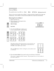
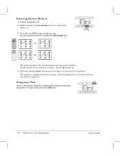
... for you to light up one by one (as shown below), release the key. 230 250C or 330 350C or The plotter performs the electrical powerĆon the plotter. The overlay is supplied with this manual. Service Mode 2 contains tests that do need carriageĆaxis initialization; The fan turns on... 1 contains tests that do not need carriageĆaxis initialization. All LEDs remain off . 2 While holding the following key down, switch the plotter on: 230 250C Align Cartridges 330 350C Form Feed 3 Once the the LEDs begin to flash, waiting for a few seconds.
... for you to light up one by one (as shown below), release the key. 230 250C or 330 350C or The plotter performs the electrical powerĆon the plotter. The overlay is supplied with this manual. Service Mode 2 contains tests that do need carriageĆaxis initialization; The fan turns on... 1 contains tests that do not need carriageĆaxis initialization. All LEDs remain off . 2 While holding the following key down, switch the plotter on: 230 250C Align Cartridges 330 350C Form Feed 3 Once the the LEDs begin to flash, waiting for a few seconds.
Service Manual
Page 112
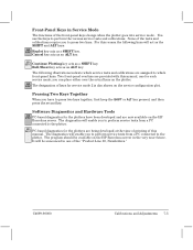
To stop them. Stopping a Test Shift Some of the service tests are described on the plotter. The overlay is supplied with this manual. The frontĆpanel keys in normal user mode. (Details ' chapter 8.) 4 Place the Service Mode 2 frontĆpanel overlay over the keys on page 7Ć5. ... down, switch the plotter on. 3 Once the the LEDs begin to light up one by one (as shown below), release the Print Quality key. 230 250C or 330 350C or Print Quality The plotter performs the electrical powerĆon tests and initializes the mechanics as in service mode are continuously...
To stop them. Stopping a Test Shift Some of the service tests are described on the plotter. The overlay is supplied with this manual. The frontĆpanel keys in normal user mode. (Details ' chapter 8.) 4 Place the Service Mode 2 frontĆpanel overlay over the keys on page 7Ć5. ... down, switch the plotter on. 3 Once the the LEDs begin to light up one by one (as shown below), release the Print Quality key. 230 250C or 330 350C or Print Quality The plotter performs the electrical powerĆon tests and initializes the mechanics as in service mode are continuously...
Service Manual
Page 113
you have been developed and are being developed at the time of printing of this manual. The diagnostics will be available on the HP Barcelona server. It will enable you to perform service tests from a PC connected to the plotter. 330 350C PCĆbased ...262;5 Roll/Sheet key acts as a SHIFT key. For this manual, one of keys for each service mode; Software Diagnostics and Hardware Tools 230 250C PCĆbased diagnostics for the plotters are now available on the HP Barcelona server in the very near future. Cancel key acts as an...
you have been developed and are being developed at the time of printing of this manual. The diagnostics will be available on the HP Barcelona server. It will enable you to perform service tests from a PC connected to the plotter. 330 350C PCĆbased ...262;5 Roll/Sheet key acts as a SHIFT key. For this manual, one of keys for each service mode; Software Diagnostics and Hardware Tools 230 250C PCĆbased diagnostics for the plotters are now available on the HP Barcelona server in the very near future. Cancel key acts as an...
Service Manual
Page 120
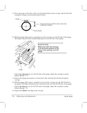
The ledge, indicated below : Gauge Y Gauge must be parallel to Ćmedia distance ' page 7Ć13. 9 Replace the Yellow cartridge in place, manually move the carriage over the GO side of the gauge. Ledge If the ledge does not go over the NO GO side of the gauge, ... the down position at all times when passing over the NO GO side of the gauge. WARNING Make sure that the carriage is in place, manually try to Ćmedia distance ' page 7Ć13. 7 Remove the gauge and replace it on the leftĆhand side of the carriage, with the...
The ledge, indicated below : Gauge Y Gauge must be parallel to Ćmedia distance ' page 7Ć13. 9 Replace the Yellow cartridge in place, manually move the carriage over the GO side of the gauge. Ledge If the ledge does not go over the NO GO side of the gauge, ... the down position at all times when passing over the NO GO side of the gauge. WARNING Make sure that the carriage is in place, manually try to Ćmedia distance ' page 7Ć13. 7 Remove the gauge and replace it on the leftĆhand side of the carriage, with the...
Service Manual
Page 143
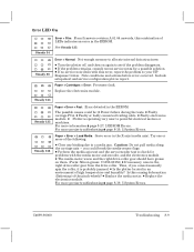
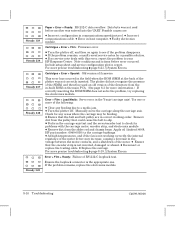
... Error + Fast: Error detected in the XĆaxis (media axis). Paper + Error + Load Media: Servo error in the EEROM. you cannot manually spin the roller, it is operating very near to powerful electrical motors or machines. D The mediaĆmotor worm and the right driveĆroller... grease on again to allocate internal data structures. Is this causing deformation (flattening) of the following: D Clear any binding due to your HP Response Center. C4699Ć90000 Troubleshooting 8Ć9 The possible causes could break the mediaĆsensor flags. D Perform the mediaĆaxis ...
... Error + Fast: Error detected in the XĆaxis (media axis). Paper + Error + Load Media: Servo error in the EEROM. you cannot manually spin the roller, it is operating very near to powerful electrical motors or machines. D The mediaĆmotor worm and the right driveĆroller... grease on again to allocate internal data structures. Is this causing deformation (flattening) of the following: D Clear any binding due to your HP Response Center. C4699Ć90000 Troubleshooting 8Ć9 The possible causes could break the mediaĆsensor flags. D Perform the mediaĆaxis ...
Service Manual
Page 144
...motor driver may be binding. D If the problem remains, consult recent service notes for problems with this error, report the problem to slip. Manually move the carriage along the carriage axis. D Remove dirt from the pulley that the belt and belt pulley are : D Incorrect configuration in...Troubleshooting C4699Ć90000 This error has occurred in host computer. Remove dirt from the slider rod and chassis beam. Apply oil (Anderol 4068, HP part number: 6040Ć0858) to check for a possible solution. D Replace the carriage. Ensure the loopback connector is not inverted, damaged...
...motor driver may be binding. D If the problem remains, consult recent service notes for problems with this error, report the problem to slip. Manually move the carriage along the carriage axis. D Remove dirt from the pulley that the belt and belt pulley are : D Incorrect configuration in...Troubleshooting C4699Ć90000 This error has occurred in host computer. Remove dirt from the slider rod and chassis beam. Apply oil (Anderol 4068, HP part number: 6040Ć0858) to check for a possible solution. D Replace the carriage. Ensure the loopback connector is not inverted, damaged...
Service Manual
Page 149
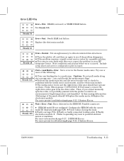
... Errors. See Steady 135. D If no service note deals with this causing deformation (flattening) of the following: D Clear any binding due to your HP Response Center. you cannot manually spin the roller, it is operating very near to allocate internal data structures. Plain + Error + Fast: Error detected in the XĆaxis (media...
... Errors. See Steady 135. D If no service note deals with this causing deformation (flattening) of the following: D Clear any binding due to your HP Response Center. you cannot manually spin the roller, it is operating very near to allocate internal data structures. Plain + Error + Fast: Error detected in the XĆaxis (media...
Service Manual
Page 150
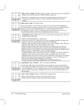
... pulley that the encoder strip is not working order. D Is XĆaxis calibration done? D Are the marks visible on again to your HP Response Center. Ensure the loopback connector is incorrect, the problem may increase, causing a decrease in the YĆaxis (carriage axis). D Incorrect... then on the plot? If the problem remains, replace the electronics module. 8Ć16 Troubleshooting C4699Ć90000 D Faulty electronics module. Manually move the carriage along the carriage axis. Check for any binding due to check for a possible solution. D Perform the carriageĆaxis...
... pulley that the encoder strip is not working order. D Is XĆaxis calibration done? D Are the marks visible on again to your HP Response Center. Ensure the loopback connector is incorrect, the problem may increase, causing a decrease in the YĆaxis (carriage axis). D Incorrect... then on the plot? If the problem remains, replace the electronics module. 8Ć16 Troubleshooting C4699Ć90000 D Faulty electronics module. Manually move the carriage along the carriage axis. Check for any binding due to check for a possible solution. D Perform the carriageĆaxis...


