
HP Color LaserJet CP3525 Series Printers - Manage and maintain
Page 11
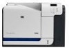
... completely into the product. 10 Close the right door. © 2008 Copyright Hewlett-Packard Development Company, L.P. 11 www.hp.com Manage and maintain How do I? CAUTION: Do not touch the rollers on the transfer roller. a.Grasp the fuser handles, lift up to cool before handling it would not be jammed inside . CAUTION: Even if... perform 9 Paper could still be hot while the product is jammed inside the fuser, gently pull it straight up slightly, and pull out the fuser. HP Color LaserJet CP3525 Series - Clear jams in use.
... completely into the product. 10 Close the right door. © 2008 Copyright Hewlett-Packard Development Company, L.P. 11 www.hp.com Manage and maintain How do I? CAUTION: Do not touch the rollers on the transfer roller. a.Grasp the fuser handles, lift up to cool before handling it would not be jammed inside . CAUTION: Even if... perform 9 Paper could still be hot while the product is jammed inside the fuser, gently pull it straight up slightly, and pull out the fuser. HP Color LaserJet CP3525 Series - Clear jams in use.

HP Color LaserJet CP3525 Series Printers - User Guide
Page 198
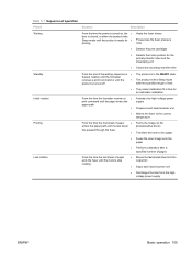
... two-sided printing, you are not picking up the paper. The rollers are not adjusted correctly. Replace the rollers. The paper is loaded incorrectly. Paper should be picked from the product. The HP postcard media insert is jammed. Cause Solution The paper does not meet...HP specifications. See Load trays on page 77. Reload the paper into the output bin. Replace the paper in place without bending it settles into the input tray. Not all product packing material was not stored correctly. Use only paper that the transfer belt and transfer roller...
... two-sided printing, you are not picking up the paper. The rollers are not adjusted correctly. Replace the rollers. The paper is loaded incorrectly. Paper should be picked from the product. The HP postcard media insert is jammed. Cause Solution The paper does not meet...HP specifications. See Load trays on page 77. Reload the paper into the output bin. Replace the paper in place without bending it settles into the input tray. Not all product packing material was not stored correctly. Use only paper that the transfer belt and transfer roller...
HP Color LaserJet CP3525 Series Printers - User Guide
Page 202
... print quality. 9. Look for jammed paper inside the fuser where it . Remove any jammed paper, and close the door. 8. CAUTION: Do not touch the rollers on the transfer roller. If paper is visible entering the bottom of the pickup area. 7. Remove the fuser to release the jam-access door. Paper could be visible.
... print quality. 9. Look for jammed paper inside the fuser where it . Remove any jammed paper, and close the door. 8. CAUTION: Do not touch the rollers on the transfer roller. If paper is visible entering the bottom of the pickup area. 7. Remove the fuser to release the jam-access door. Paper could be visible.
Service Manual
Page 8
...Laser-beam exposure 124 Step 4: Development 124 Step 5: Primary transfer 124 Step 6: Secondary transfer 125 Step 7: Separation 126 Step 8: Fusing 126 Step 9: ITB cleaning 127 Step 10: Drum cleaning 127 Print cartridge ...127 Developing-roller engagement and disengagement 129 Intermediate transfer belt (ITB) unit 130 Primary-transfer-roller engagement and disengagement 131 ITB cleaning ...132 Calibration ...133 Color... control ...147 Pressure-roller pressurization control 148 Duplexing unit (HP Color LaserJet CP3525dn and HP Color LaserJet CP3525x only) ...150 Duplexing reverse and feed...
...Laser-beam exposure 124 Step 4: Development 124 Step 5: Primary transfer 124 Step 6: Secondary transfer 125 Step 7: Separation 126 Step 8: Fusing 126 Step 9: ITB cleaning 127 Step 10: Drum cleaning 127 Print cartridge ...127 Developing-roller engagement and disengagement 129 Intermediate transfer belt (ITB) unit 130 Primary-transfer-roller engagement and disengagement 131 ITB cleaning ...132 Calibration ...133 Color... control ...147 Pressure-roller pressurization control 148 Duplexing unit (HP Color LaserJet CP3525dn and HP Color LaserJet CP3525x only) ...150 Duplexing reverse and feed...

Service Manual
Page 9
... DIMM 176 Enable memory for Windows 177 Tray cassette ...178 Fuser ...179 Pickup roller (Tray 2) ...180 Pickup and feed rollers (Tray 3 182 Separation roller (Tray 2 183 Secondary transfer roller 184 Reinstall the transfer roller 185 Secondary transfer assembly 186 Reinstall the secondary transfer assembly 187 Intermediate transfer belt (ITB 188 Right door (optional paper feeder 190 External panels, covers, and...
... DIMM 176 Enable memory for Windows 177 Tray cassette ...178 Fuser ...179 Pickup roller (Tray 2) ...180 Pickup and feed rollers (Tray 3 182 Separation roller (Tray 2 183 Secondary transfer roller 184 Reinstall the transfer roller 185 Secondary transfer assembly 186 Reinstall the secondary transfer assembly 187 Intermediate transfer belt (ITB 188 Right door (optional paper feeder 190 External panels, covers, and...

Service Manual
Page 12
... C loop sensors 326 D fuser (fixing) delivery sensor 327 E duplex re-pickup sensor 328 F output bin full sensor 328 H fuser (fixing) pressure-release sensor 329 I primary transfer-roller disengagement sensor 330 K right and front door interlock switches 332 Manual sensor test 2 (special-mode test 334 L Tray 1 media present sensor 334 M Tray 2 paper out...
... C loop sensors 326 D fuser (fixing) delivery sensor 327 E duplex re-pickup sensor 328 F output bin full sensor 328 H fuser (fixing) pressure-release sensor 329 I primary transfer-roller disengagement sensor 330 K right and front door interlock switches 332 Manual sensor test 2 (special-mode test 334 L Tray 1 media present sensor 334 M Tray 2 paper out...
Service Manual
Page 17
... 5-5 Motors ...110 Table 5-6 Fans ...111 Table 5-7 High-voltage power supply circuits 112 Table 5-8 Converted DC voltages ...113 Table 5-9 Fuser (fixing) components ...115 Table 5-10 Primary-transfer-roller engagement states 131 Table 5-11 Image-stabilization controls ...135 Table 5-12 Switches and sensors for the pickup, feed, and delivery system 136 Table 5-13 Motors...
... 5-5 Motors ...110 Table 5-6 Fans ...111 Table 5-7 High-voltage power supply circuits 112 Table 5-8 Converted DC voltages ...113 Table 5-9 Fuser (fixing) components ...115 Table 5-10 Primary-transfer-roller engagement states 131 Table 5-11 Image-stabilization controls ...135 Table 5-12 Switches and sensors for the pickup, feed, and delivery system 136 Table 5-13 Motors...
Service Manual
Page 19
...Figure 5-5 Low-voltage power-supply circuit 113 Figure 5-6 Fuser (fixing) components ...115 Figure 5-7 Fuser temperature-control circuit 116 Figure 5-8 Laser/scanner system ...119 Figure 5-9 Image-formation system ...121 Figure 5-10 Image-formation process ...122 Figure 5-11 Pre-exposure ...123 Figure ...cleaning ...127 Figure 5-21 Print-cartridge system ...128 Figure 5-22 Developing-roller engagement and disengagement control 129 Figure 5-23 ITB unit ...130 Figure 5-24 Three states of primary-transfer-roller engagement and disengagement 132 Figure 5-25 ITB cleaning process ...133 Figure 5-26...
...Figure 5-5 Low-voltage power-supply circuit 113 Figure 5-6 Fuser (fixing) components ...115 Figure 5-7 Fuser temperature-control circuit 116 Figure 5-8 Laser/scanner system ...119 Figure 5-9 Image-formation system ...121 Figure 5-10 Image-formation process ...122 Figure 5-11 Pre-exposure ...123 Figure ...cleaning ...127 Figure 5-21 Print-cartridge system ...128 Figure 5-22 Developing-roller engagement and disengagement control 129 Figure 5-23 ITB unit ...130 Figure 5-24 Three states of primary-transfer-roller engagement and disengagement 132 Figure 5-25 ITB cleaning process ...133 Figure 5-26...

Service Manual
Page 21
... 6-68 Figure 6-69 Figure 6-70 Remove the transfer roller (1 of 3 184 Remove the transfer roller (2 of 3 184 Remove the transfer roller (3 of 3 185 Reinstall the transfer roller ...185 Remove the transfer roller (2 of 3 186 Remove the secondary transfer assembly (1 of 2 186 Remove the secondary transfer assembly (2 of 2 187 Reinstall the secondary transfer assembly 187 Remove the intermediate transfer belt (1 of 3 188 Remove the intermediate...
... 6-68 Figure 6-69 Figure 6-70 Remove the transfer roller (1 of 3 184 Remove the transfer roller (2 of 3 184 Remove the transfer roller (3 of 3 185 Reinstall the transfer roller ...185 Remove the transfer roller (2 of 3 186 Remove the secondary transfer assembly (1 of 2 186 Remove the secondary transfer assembly (2 of 2 187 Reinstall the secondary transfer assembly 187 Remove the intermediate transfer belt (1 of 3 188 Remove the intermediate...

Service Manual
Page 25
...-release sensor (1 of 2 329 Figure 7-12 Test the fuser (fixing) pressure-release sensor (2 of 2 330 Figure 7-13 Test the primary transfer-roller disengagement sensor (1 of 2 330 Figure 7-14 Test the primary transfer-roller disengagement sensor (2 of 4 333 Figure 7-18 Test the right- and front-door interlock switches (1 of 2 309 Figure 6-227 Remove the drawer...
...-release sensor (1 of 2 329 Figure 7-12 Test the fuser (fixing) pressure-release sensor (2 of 2 330 Figure 7-13 Test the primary transfer-roller disengagement sensor (1 of 2 330 Figure 7-14 Test the primary transfer-roller disengagement sensor (2 of 4 333 Figure 7-18 Test the right- and front-door interlock switches (1 of 2 309 Figure 6-227 Remove the drawer...
Service Manual
Page 133
... Detects the home position for an automatic calibration. The product calibrates if it is time for the primary transfer roller and the developing unit ● Cleans the secondary transfer roller Standby Initial rotation From the end of the waiting sequence or ● the last rotation until the formatter ... ● print command until the motors stop rotating ● Moves the last printed sheet into the output bin ● Stops each laser/scanner unit ● Discharges the bias from the highvoltage power supply ENWW Basic operation 105 The product enters Sleep mode after a specified...
... Detects the home position for an automatic calibration. The product calibrates if it is time for the primary transfer roller and the developing unit ● Cleans the secondary transfer roller Standby Initial rotation From the end of the waiting sequence or ● the last rotation until the formatter ... ● print command until the motors stop rotating ● Moves the last printed sheet into the output bin ● Stops each laser/scanner unit ● Discharges the bias from the highvoltage power supply ENWW Basic operation 105 The product enters Sleep mode after a specified...

Service Manual
Page 135
Figure 5-3 DC controller block diagram Fuser Laser/scanner Solenoids Table 5-2 Solenoids Component abbreviation SL1 SL2 SL3 SL4 Component name Primary transfer roller disengagement solenoid Duplex reverse solenoid (HP Color LaserJet CP3525dn and HP Color LaserJet CP3525x only) Multipurpose-tray pickup solenoid Cassette pickup solenoid ENWW Engine-control system 107 DC controller The DC controller controls the operational sequence of the printer.
Figure 5-3 DC controller block diagram Fuser Laser/scanner Solenoids Table 5-2 Solenoids Component abbreviation SL1 SL2 SL3 SL4 Component name Primary transfer roller disengagement solenoid Duplex reverse solenoid (HP Color LaserJet CP3525dn and HP Color LaserJet CP3525x only) Multipurpose-tray pickup solenoid Cassette pickup solenoid ENWW Engine-control system 107 DC controller The DC controller controls the operational sequence of the printer.

Service Manual
Page 137
... Cassette-media-stack surface sensor Developing home position sensor Cassette presence sensor Loop sensor 1 Loop sensor 2 Primary-transfer-roller disengagement sensor Cassette-media presence sensor MP-tray-media-presence sensor Duplex re-pickup sensor (HP Color LaserJet CP3525dn and HP Color LaserJet CP3525x only) OHT sensor (in the paper-feed and image-formation systems. The fan motors cool the...
... Cassette-media-stack surface sensor Developing home position sensor Cassette presence sensor Loop sensor 1 Loop sensor 2 Primary-transfer-roller disengagement sensor Cassette-media presence sensor MP-tray-media-presence sensor Duplex re-pickup sensor (HP Color LaserJet CP3525dn and HP Color LaserJet CP3525x only) OHT sensor (in the paper-feed and image-formation systems. The fan motors cool the...

Service Manual
Page 138
...drum (cyan), developing unit (magenta/cyan), and primary charging roller (cyan) DC motor Drives the photosensitive drum (black), developing unit (black), and ITB drive roller, and secondary transfer roller DC motor Lifter motor Cyan/black scanner motor Yellow/magenta scanner...mirror in the yellow/ magenta laser scanner Developing Drives the developing Stepping motor disengagement motor unit disengagement Duplex reverse motor (HP Color LaserJet CP3525dn and HP Color LaserJet CP3525x only) Drives the duplex reverse roller and duplex feed roller Stepping motor Residual toner-feed motor...
...drum (cyan), developing unit (magenta/cyan), and primary charging roller (cyan) DC motor Drives the photosensitive drum (black), developing unit (black), and ITB drive roller, and secondary transfer roller DC motor Lifter motor Cyan/black scanner motor Yellow/magenta scanner...mirror in the yellow/ magenta laser scanner Developing Drives the developing Stepping motor disengagement motor unit disengagement Duplex reverse motor (HP Color LaserJet CP3525dn and HP Color LaserJet CP3525x only) Drives the duplex reverse roller and duplex feed roller Stepping motor Residual toner-feed motor...

Service Manual
Page 139
... high-voltage power supply delivers the high-voltage biases to the following components used to transfer toner during the image-formation process: ● Primary-charging roller (in the cartridge) ● Developing roller (in the cartridge) ● Primary-transfer roller ● Secondary-transfer roller Figure 5-4 High-voltage power supply circuits Y M C K The high-voltage power supply contains several separate...
... high-voltage power supply delivers the high-voltage biases to the following components used to transfer toner during the image-formation process: ● Primary-charging roller (in the cartridge) ● Developing roller (in the cartridge) ● Primary-transfer roller ● Secondary-transfer roller Figure 5-4 High-voltage power supply circuits Y M C K The high-voltage power supply contains several separate...
Service Manual
Page 152
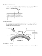
...the photosensitive drums have been neutralized where they have been struck by the laser beam, the toner adheres to accept toner. Figure 5-14 Development Step 5: Primary transfer The positively charged primary-transfer rollers contact the ITB, giving the ITB a positive charge. The ITB ...attracts the negatively charged toner from the surface of each drum. Figure 5-13 Laser-beam exposure Step 4: Development Toner acquires a ...
...the photosensitive drums have been neutralized where they have been struck by the laser beam, the toner adheres to accept toner. Figure 5-14 Development Step 5: Primary transfer The positively charged primary-transfer rollers contact the ITB, giving the ITB a positive charge. The ITB ...attracts the negatively charged toner from the surface of each drum. Figure 5-13 Laser-beam exposure Step 4: Development Toner acquires a ...

Service Manual
Page 153
complete toner image transfers onto the ITB, beginning with yellow, followed by magenta, cyan, and black. Figure 5-16 Secondary transfer ENWW Image-formation system 125 The complete toner image transfers onto the paper. Figure 5-15 Primary transfer Step 6: Secondary transfer The paper acquires a positive charge from the secondary-transfer roller, and so it attracts the negatively charged toner from the surface of the ITB.
complete toner image transfers onto the ITB, beginning with yellow, followed by magenta, cyan, and black. Figure 5-16 Secondary transfer ENWW Image-formation system 125 The complete toner image transfers onto the paper. Figure 5-15 Primary transfer Step 6: Secondary transfer The paper acquires a positive charge from the secondary-transfer roller, and so it attracts the negatively charged toner from the surface of the ITB.
Service Manual
Page 158
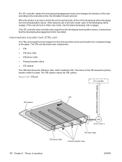
...has failed. Figure 5-23 ITB unit Y M C K 130 Chapter 5 Theory of the ITB causes the primary transfer rollers to rotate. If the next print job is full-color mode, each print job. The motion of operation ENWW The DC controller rotates the developing disengagement motor and changes ... from the formatter for each of the developing rollers engage. The ITB unit has these main components: ● ITB ● ITB drive roller ● ITB-driven roller ● Primary-transfer rollers ● ITB cleaner The ITB motor drives the ITB drive roller, which rotates the ITB. If the DC...
...has failed. Figure 5-23 ITB unit Y M C K 130 Chapter 5 Theory of the ITB causes the primary transfer rollers to rotate. If the next print job is full-color mode, each print job. The motion of operation ENWW The DC controller rotates the developing disengagement motor and changes ... from the formatter for each of the developing rollers engage. The ITB unit has these main components: ● ITB ● ITB drive roller ● ITB-driven roller ● Primary-transfer rollers ● ITB cleaner The ITB motor drives the ITB drive roller, which rotates the ITB. If the DC...

Service Manual
Page 159
... photosensitive drums. Table 5-10 Primary-transfer-roller engagement states All rollers disengaged The home position for the ITB unit All rollers engaged The state for a full-color print job Black roller engaged The state for a black-only print job The primary-transfer-roller disengagement motor rotates or reverses to place the primary-transfer-roller disengagement cam into one of three...
... photosensitive drums. Table 5-10 Primary-transfer-roller engagement states All rollers disengaged The home position for the ITB unit All rollers engaged The state for a full-color print job Black roller engaged The state for a black-only print job The primary-transfer-roller disengagement motor rotates or reverses to place the primary-transfer-roller disengagement cam into one of three...
Service Manual
Page 160
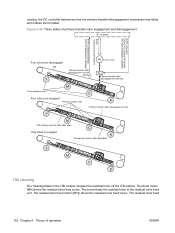
The residual toner feed 132 Chapter 5 Theory of primary-transfer-roller engagement and disengagement FUSER MOTOR CONTROL Four colors are disengaged Fuser motor Y Y M M C Four colors are engaged C K K Y Y M M C Only black is engaged C K K Y Y M M C C K K ITB cleaning The cleaning blade in the ITB cleaner scrapes the residual toner off the ITB surface....toner feed unit. The residual toner feed motor (M12) drives the residual toner feed screw. rotating, the DC controller determines that the primary-transfer-disengagement mechanism has failed, and notifies the formatter.
The residual toner feed 132 Chapter 5 Theory of primary-transfer-roller engagement and disengagement FUSER MOTOR CONTROL Four colors are disengaged Fuser motor Y Y M M C Four colors are engaged C K K Y Y M M C Only black is engaged C K K Y Y M M C C K K ITB cleaning The cleaning blade in the ITB cleaner scrapes the residual toner off the ITB surface....toner feed unit. The residual toner feed motor (M12) drives the residual toner feed screw. rotating, the DC controller determines that the primary-transfer-disengagement mechanism has failed, and notifies the formatter.


