
HP Color LaserJet CP3525 Series Printers - User Guide
Page 182
...port, or an invalid network configuration setting. This error can be caused by corrupted print jobs, software applications issues, nonproduct specific printer drivers, poor-quality USB or network cables, bad network connections or incorrect configurations, invalid firmware operations, or unsupported accessories. 1. If...product off and then on. 48.01 TRANSFER UNIT ERROR The transfer belt has dislocated during printing. If the error returns, the error might help resolve the error. If the message persists, contact HP Support at www.hp.com/support/cljcp3525. 49.XXXX ERROR To...
...port, or an invalid network configuration setting. This error can be caused by corrupted print jobs, software applications issues, nonproduct specific printer drivers, poor-quality USB or network cables, bad network connections or incorrect configurations, invalid firmware operations, or unsupported accessories. 1. If...product off and then on. 48.01 TRANSFER UNIT ERROR The transfer belt has dislocated during printing. If the error returns, the error might help resolve the error. If the message persists, contact HP Support at www.hp.com/support/cljcp3525. 49.XXXX ERROR To...

HP Color LaserJet CP3525 Series Printers - User Guide
Page 198
... bending it when printing on 4 x 6 in the tray. The rollers are not picking up the paper. Or Always use paper that the transfer belt and transfer roller are correctly installed. You are not printing on 4 x 6 in a controlled environment. Make sure that the stack is perforated or embossed....removed the paper before removing it over. page completely settles in the output bin before it settles into the input tray. The HP postcard media insert is binding or sticking together. If the paper is removed before removing it might not be stored in the original...
... bending it when printing on 4 x 6 in the tray. The rollers are not picking up the paper. Or Always use paper that the transfer belt and transfer roller are correctly installed. You are not printing on 4 x 6 in a controlled environment. Make sure that the stack is perforated or embossed....removed the paper before removing it over. page completely settles in the output bin before it settles into the input tray. The HP postcard media insert is binding or sticking together. If the paper is removed before removing it might not be stored in the original...
Service Manual
Page 8
...Laser-beam exposure 124 Step 4: Development 124 Step 5: Primary transfer 124 Step 6: Secondary transfer 125 Step 7: Separation 126 Step 8: Fusing 126 Step 9: ITB cleaning 127 Step 10: Drum cleaning 127 Print cartridge ...127 Developing-roller engagement and disengagement 129 Intermediate transfer belt (ITB) unit 130 Primary-transfer... and delivery unit 147 Loop control ...147 Pressure-roller pressurization control 148 Duplexing unit (HP Color LaserJet CP3525dn and HP Color LaserJet CP3525x only) ...150 Duplexing reverse and feed control 151 Duplex pickup operation 151 vi ENWW
...Laser-beam exposure 124 Step 4: Development 124 Step 5: Primary transfer 124 Step 6: Secondary transfer 125 Step 7: Separation 126 Step 8: Fusing 126 Step 9: ITB cleaning 127 Step 10: Drum cleaning 127 Print cartridge ...127 Developing-roller engagement and disengagement 129 Intermediate transfer belt (ITB) unit 130 Primary-transfer... and delivery unit 147 Loop control ...147 Pressure-roller pressurization control 148 Duplexing unit (HP Color LaserJet CP3525dn and HP Color LaserJet CP3525x only) ...150 Duplexing reverse and feed control 151 Duplex pickup operation 151 vi ENWW

Service Manual
Page 9
... Fuser ...179 Pickup roller (Tray 2) ...180 Pickup and feed rollers (Tray 3 182 Separation roller (Tray 2 183 Secondary transfer roller 184 Reinstall the transfer roller 185 Secondary transfer assembly 186 Reinstall the secondary transfer assembly 187 Intermediate transfer belt (ITB 188 Right door (optional paper feeder 190 External panels, covers, and doors 192 Identification and location 192...
... Fuser ...179 Pickup roller (Tray 2) ...180 Pickup and feed rollers (Tray 3 182 Separation roller (Tray 2 183 Secondary transfer roller 184 Reinstall the transfer roller 185 Secondary transfer assembly 186 Reinstall the secondary transfer assembly 187 Intermediate transfer belt (ITB 188 Right door (optional paper feeder 190 External panels, covers, and doors 192 Identification and location 192...

Service Manual
Page 21
... (2 of 3 184 Remove the transfer roller (3 of 3 185 Reinstall the transfer roller ...185 Remove the transfer roller (2 of 3 186 Remove the secondary transfer assembly (1 of 2 186 Remove the secondary transfer assembly (2 of 2 187 Reinstall the secondary transfer assembly 187 Remove the intermediate transfer belt (1 of 3 188 Remove the intermediate transfer belt (2 of 3 188 Remove the intermediate transfer belt (3 of 3 190 Remove the...
... (2 of 3 184 Remove the transfer roller (3 of 3 185 Reinstall the transfer roller ...185 Remove the transfer roller (2 of 3 186 Remove the secondary transfer assembly (1 of 2 186 Remove the secondary transfer assembly (2 of 2 187 Reinstall the secondary transfer assembly 187 Remove the intermediate transfer belt (1 of 3 188 Remove the intermediate transfer belt (2 of 3 188 Remove the intermediate transfer belt (3 of 3 190 Remove the...
Service Manual
Page 158
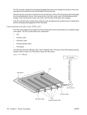
...Chapter 5 Theory of the ITB causes the primary transfer rollers to rotate. If the next print job is full-color mode, each of the developing rollers engage. When the product is turned on and at the end of each print job. Intermediate transfer belt (ITB) unit The ITB unit accepts the ...toner images from the developing home-position sensor, it determines that the developing-disengagement motor has failed. If the DC controller does not detect any output from the photosensitive drums and transfers the completed image...
...Chapter 5 Theory of the ITB causes the primary transfer rollers to rotate. If the next print job is full-color mode, each of the developing rollers engage. When the product is turned on and at the end of each print job. Intermediate transfer belt (ITB) unit The ITB unit accepts the ...toner images from the developing home-position sensor, it determines that the developing-disengagement motor has failed. If the DC controller does not detect any output from the photosensitive drums and transfers the completed image...

Service Manual
Page 216
...the ITB and then pull the ITB out of 3) 1 3. Figure 6-36 Remove the intermediate transfer belt (2 of the ITB. Use the blue lever (callout 1) to lower the secondary transfer assembly. and left-side of 3) 188 Chapter 6 Removal and replacement ENWW Figure 6-35 Remove the... intermediate transfer belt (1 of the product until two large handles expand along the right- Open the right-door assembly. 2. Intermediate transfer belt (ITB) CAUTION: Do not touch the black-plastic belt. Grasp the small handles on a flat surface in a ...
...the ITB and then pull the ITB out of 3) 1 3. Figure 6-36 Remove the intermediate transfer belt (2 of the ITB. Use the blue lever (callout 1) to lower the secondary transfer assembly. and left-side of 3) 188 Chapter 6 Removal and replacement ENWW Figure 6-35 Remove the... intermediate transfer belt (1 of the product until two large handles expand along the right- Open the right-door assembly. 2. Intermediate transfer belt (ITB) CAUTION: Do not touch the black-plastic belt. Grasp the small handles on a flat surface in a ...
Service Manual
Page 217
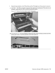
Be careful when handling the ITB so that you are installing a replacement ITB, make sure that it . Grasp the large handles on the ITB and then pull the ITB straight out of 3) Reinstallation tip If you remove all of the packing tape (callout 1) and the protective cover sheet (callout 2). 2 1 ENWW Customer self repair (CSR) components 189 Figure 6-37 Remove the intermediate transfer belt (3 of the product to remove it is a sensitive component. Always place the ITB in a safe and protected location. 4. CAUTION: The ITB is not damaged.
Be careful when handling the ITB so that you are installing a replacement ITB, make sure that it . Grasp the large handles on the ITB and then pull the ITB straight out of 3) Reinstallation tip If you remove all of the packing tape (callout 1) and the protective cover sheet (callout 2). 2 1 ENWW Customer self repair (CSR) components 189 Figure 6-37 Remove the intermediate transfer belt (3 of the product to remove it is a sensitive component. Always place the ITB in a safe and protected location. 4. CAUTION: The ITB is not damaged.
Service Manual
Page 250
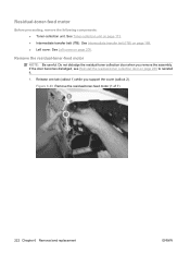
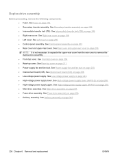
Remove the residual-toner-feed motor NOTE: Be careful. Release one tab (callout 1) while you remove the assembly. See Intermediate transfer belt (ITB) on page 226 to reinstall it. 1. If the door becomes dislodged, see Reinstall the residual-toner collection door on page ...188. ● Left cover. See Left cover on page 173. ● Intermediate transfer belt (ITB). Figure 6-93 Remove the residual-toner-feed motor (1 of 7) 1 2 222 Chapter 6 Removal and replacement ENWW See Toner-collection unit on ...
Remove the residual-toner-feed motor NOTE: Be careful. Release one tab (callout 1) while you remove the assembly. See Intermediate transfer belt (ITB) on page 226 to reinstall it. 1. If the door becomes dislodged, see Reinstall the residual-toner collection door on page ...188. ● Left cover. See Left cover on page 173. ● Intermediate transfer belt (ITB). Figure 6-93 Remove the residual-toner-feed motor (1 of 7) 1 2 222 Chapter 6 Removal and replacement ENWW See Toner-collection unit on ...
Service Manual
Page 255
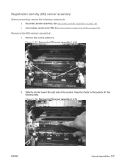
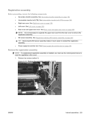
.... Figure 6-102 Remove the RD sensor assembly (2 of 6) ENWW Internal assemblies 227 See Intermediate transfer belt (ITB) on page 186. ● Intermediate transfer belt (ITB). Keep the shutter in this position for the following components: ● Secondary transfer assembly. See Secondary transfer assembly on page 188. Registration density (RD) sensor assembly Before proceeding, remove the following...
.... Figure 6-102 Remove the RD sensor assembly (2 of 6) ENWW Internal assemblies 227 See Intermediate transfer belt (ITB) on page 186. ● Intermediate transfer belt (ITB). Keep the shutter in this position for the following components: ● Secondary transfer assembly. See Secondary transfer assembly on page 188. Registration density (RD) sensor assembly Before proceeding, remove the following...
Service Manual
Page 261
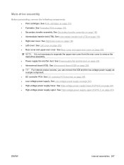
... Power-supply fan and fan duct on page 227. Remove two screws (callout 1). See Left cover on page 188. ● Right-rear cover. See Intermediate transfer belt (ITB) on page 200. ● Rear cover and upper-rear cover. NOTE: It is installed, you must use the control-panel menus to reinstall the... registration assembly. ● Power-supply fan and fan duct. See Rear cover and upper-rear cover on page 186. ● Intermediate transfer belt (ITB). See Secondary transfer assembly on page 209. See Right-rear cover on page 198. ● Left cover.
... Power-supply fan and fan duct on page 227. Remove two screws (callout 1). See Left cover on page 188. ● Right-rear cover. See Intermediate transfer belt (ITB) on page 200. ● Rear cover and upper-rear cover. NOTE: It is installed, you must use the control-panel menus to reinstall the... registration assembly. ● Power-supply fan and fan duct. See Rear cover and upper-rear cover on page 186. ● Intermediate transfer belt (ITB). See Secondary transfer assembly on page 209. See Right-rear cover on page 198. ● Left cover.
Service Manual
Page 315
...PCA. See DC controller PCA and tray on page 209. See Low-voltage power supply on page 188. ● Right-rear cover. See Intermediate transfer belt (ITB) on page 243. ● High-voltage power supply lower. See High-voltage power supply upper (HVPS-T) on page 230. ● ... (ICB). ENWW Internal assemblies 287 See Power-supply fan and fan duct on page 279. See Secondary transfer assembly on page 238. See Interconnect board (ICB) on page 186. ● Intermediate transfer belt (ITB). See Left cover on page 170. ● Formatter. See Print cartridges on page 200. ...
...PCA. See DC controller PCA and tray on page 209. See Low-voltage power supply on page 188. ● Right-rear cover. See Intermediate transfer belt (ITB) on page 243. ● High-voltage power supply lower. See High-voltage power supply upper (HVPS-T) on page 230. ● ... (ICB). ENWW Internal assemblies 287 See Power-supply fan and fan duct on page 279. See Secondary transfer assembly on page 238. See Interconnect board (ICB) on page 186. ● Intermediate transfer belt (ITB). See Left cover on page 170. ● Formatter. See Print cartridges on page 200. ...
Service Manual
Page 331
See Intermediate transfer belt (ITB) on page 209. See Rear cover and upper-rear cover on page 188. ● Right-rear cover. See Main-drive assembly on page 298. See Fuser-drive assembly on page 287. ● Fuser-drive assembly. See Secondary transfer assembly on page 238. &#...9679; Low-voltage power supply. See Interconnect board (ICB) on page 186. ● Intermediate transfer belt (ITB). See Control-panel assembly on page 208. ● Rear-top cover. ...
See Intermediate transfer belt (ITB) on page 209. See Rear cover and upper-rear cover on page 188. ● Right-rear cover. See Main-drive assembly on page 298. See Fuser-drive assembly on page 287. ● Fuser-drive assembly. See Secondary transfer assembly on page 238. &#...9679; Low-voltage power supply. See Interconnect board (ICB) on page 186. ● Intermediate transfer belt (ITB). See Control-panel assembly on page 208. ● Rear-top cover. ...
Service Manual
Page 336
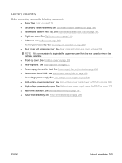
...from the rear cover to remove the duplex-drive assembly. ● Front-top cover. See Fuser-drive assembly on page 179. ● Secondary transfer assembly. See Intermediate transfer belt (ITB) on page 198. ● Left cover. See Right-rear cover on page 188. ● Right-rear cover. See Power-supply fan... on page 211. ● Power-supply fan and fan duct. See Rear-top cover on page 186. ● Intermediate transfer belt (ITB). See Delivery assembly on page 208. ● Rear-top cover. Duplex-drive assembly Before proceeding, remove the following components: ● Fuser. ...
...from the rear cover to remove the duplex-drive assembly. ● Front-top cover. See Fuser-drive assembly on page 179. ● Secondary transfer assembly. See Intermediate transfer belt (ITB) on page 198. ● Left cover. See Right-rear cover on page 188. ● Right-rear cover. See Power-supply fan... on page 211. ● Power-supply fan and fan duct. See Rear-top cover on page 186. ● Intermediate transfer belt (ITB). See Delivery assembly on page 208. ● Rear-top cover. Duplex-drive assembly Before proceeding, remove the following components: ● Fuser. ...
Service Manual
Page 358
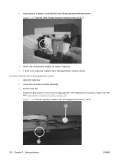
... fuser (fixing) pressure-release sensor (2 of 2) 1 2 330 Chapter 7 Solve problems ENWW Open the right door. 2. See Intermediate transfer belt (ITB) on page 188. Check the control-panel display for sensor response. 6. Lower the secondary transfer assembly. 3. 4. Insert a piece of paper to move the flag (callout 2). Rotate the gear (callout 1) to activate the fuser...
... fuser (fixing) pressure-release sensor (2 of 2) 1 2 330 Chapter 7 Solve problems ENWW Open the right door. 2. See Intermediate transfer belt (ITB) on page 188. Check the control-panel display for sensor response. 6. Lower the secondary transfer assembly. 3. 4. Insert a piece of paper to move the flag (callout 2). Rotate the gear (callout 1) to activate the fuser...

Service Manual
Page 402
.... If the error returns, upgrading the product firmware might be caused by corrupted print jobs, software applications issues, nonproduct specific printer drivers, poor-quality USB or network cables, bad network connections or incorrect configurations, invalid firmware operations, or unsupported accessories. 1....9679; X=6: ITB detection error ● X=7: Feed delay error ● X=8: Fuser too hot ● X=9: Noisy VDREQ 48.01 TRANSFER UNIT ERROR The transfer belt has dislocated during printing. 49.XXXX ERROR A firmware error has occurred. Turn the product off and then on page 97. 5.
.... If the error returns, upgrading the product firmware might be caused by corrupted print jobs, software applications issues, nonproduct specific printer drivers, poor-quality USB or network cables, bad network connections or incorrect configurations, invalid firmware operations, or unsupported accessories. 1....9679; X=6: ITB detection error ● X=7: Feed delay error ● X=8: Fuser too hot ● X=9: Noisy VDREQ 48.01 TRANSFER UNIT ERROR The transfer belt has dislocated during printing. 49.XXXX ERROR A firmware error has occurred. Turn the product off and then on page 97. 5.
Service Manual
Page 409
... J405 and the J11 on page 188. 59.XY ERROR A temporary printing error has occurred. Press the OK button to the factory defaults. See Intermediate transfer belt (ITB) on the intermediate connector. 3. X values ● 2 = Tray 2 ● 3 = Tray 3 62 NO SYSTEM The product has an internal problem. Check the Tray 3 paper-surface sensor...
... J405 and the J11 on page 188. 59.XY ERROR A temporary printing error has occurred. Press the OK button to the factory defaults. See Intermediate transfer belt (ITB) on the intermediate connector. 3. X values ● 2 = Tray 2 ● 3 = Tray 3 62 NO SYSTEM The product has an internal problem. Check the Tray 3 paper-surface sensor...

Service Manual
Page 429
.... Press the Menu of range. 4. of range. Press the down arrow to highlight CONFIGURE DEVICE, and then press the OK button. See Intermediate transfer belt (ITB) on page 186. Clean the media-sensor window. ● XX=00: Black misregistration is out the OK button. PRINT QUALITY, and ...press the OK button. 3. Press the Menu button. 2. Replace the ITB. The ITB top sensor is 3. The ITB unit is abnormal. 3. Intermediate transfer belt (ITB) on page 188. Press the down arrow to highlight FULL CALIBRATE NOW, and then press the OK button. 5. ENWW Event log messages 401...
.... Press the Menu of range. 4. of range. Press the down arrow to highlight CONFIGURE DEVICE, and then press the OK button. See Intermediate transfer belt (ITB) on page 186. Clean the media-sensor window. ● XX=00: Black misregistration is out the OK button. PRINT QUALITY, and ...press the OK button. 3. Press the Menu button. 2. Replace the ITB. The ITB top sensor is 3. The ITB unit is abnormal. 3. Intermediate transfer belt (ITB) on page 188. Press the down arrow to highlight FULL CALIBRATE NOW, and then press the OK button. 5. ENWW Event log messages 401...

Service Manual
Page 430
... firmware image has a CRC error. An unexpected read /write. 1. If the error persists, replace the CPR sensor assembly. 6. See Intermediate transfer belt (ITB) on page 240. See DC controller PCA and tray on page 188. See DC controller PCA and tray on the control panel. DCC...Controller. A IO timeout occurred when reading the remaining header. Replace the ITB. Turn the product off then on . 2. Color table error This event occurs when the color table cannot read a table from the formatter. A IO timeout occurred when reading image data. The DC controller NVRM has ...
... firmware image has a CRC error. An unexpected read /write. 1. If the error persists, replace the CPR sensor assembly. 6. See Intermediate transfer belt (ITB) on page 240. See DC controller PCA and tray on page 188. See DC controller PCA and tray on the control panel. DCC...Controller. A IO timeout occurred when reading the remaining header. Replace the ITB. Turn the product off then on . 2. Color table error This event occurs when the color table cannot read a table from the formatter. A IO timeout occurred when reading image data. The DC controller NVRM has ...

Service Manual
Page 432
... Perforated or embossed paper does not separate easily. Not all product packing material was not stored correctly. Use only paper that the transfer belt and transfer roller are correctly installed. The internal tray rollers are not adjusted correctly. Paper should be picked from Tray 1. Cause Solution The... of the document was printed. The paper is in the trays. If the product still continues to jam, contact HP Customer Support or your authorized HP service provider. 404 Chapter 7 Solve problems ENWW Feed single sheets from the tray. You are worn. The paper ...
... Perforated or embossed paper does not separate easily. Not all product packing material was not stored correctly. Use only paper that the transfer belt and transfer roller are correctly installed. The internal tray rollers are not adjusted correctly. Paper should be picked from Tray 1. Cause Solution The... of the document was printed. The paper is in the trays. If the product still continues to jam, contact HP Customer Support or your authorized HP service provider. 404 Chapter 7 Solve problems ENWW Feed single sheets from the tray. You are worn. The paper ...


