
Service Manual
Page 11
... 2 or drum motor 3 284 Fuser motor ...285 Remove the fuser motor 286 Main-drive assembly ...287 Remove the main-drive assembly 288 Reinstall the main-drive assembly 292 Fuser-drive assembly ...298 Remove the fuser-drive assembly 299 Reinstall the fuser-drive assembly 302 Delivery assembly ...303 Remove the delivery assembly 304 Reinstall the delivery assembly 307 Duplex-drive assembly ...308 Remove the duplex-drive assembly 309 Optional paper feeder assembly (Tray 3 310 Drawer connector...
... 2 or drum motor 3 284 Fuser motor ...285 Remove the fuser motor 286 Main-drive assembly ...287 Remove the main-drive assembly 288 Reinstall the main-drive assembly 292 Fuser-drive assembly ...298 Remove the fuser-drive assembly 299 Reinstall the fuser-drive assembly 302 Delivery assembly ...303 Remove the delivery assembly 304 Reinstall the delivery assembly 307 Duplex-drive assembly ...308 Remove the duplex-drive assembly 309 Optional paper feeder assembly (Tray 3 310 Drawer connector...
Service Manual
Page 24
... Remove the fuser motor ...286 Remove the main-drive assembly (1 of 7 288 Remove the main-drive assembly (2 of 7 288 Remove the main-drive assembly (3 of 7 289 Remove the main-drive assembly (4 of 7 289 Remove the main-drive assembly (5 of 7 290 Remove the main-drive assembly (6 of 7 290 Remove the main-drive assembly (7 of 7 291 Reinstall the main-drive assembly (1 of 11 292 Reinstall the main-drive assembly (2 of 11...
... Remove the fuser motor ...286 Remove the main-drive assembly (1 of 7 288 Remove the main-drive assembly (2 of 7 288 Remove the main-drive assembly (3 of 7 289 Remove the main-drive assembly (4 of 7 289 Remove the main-drive assembly (5 of 7 290 Remove the main-drive assembly (6 of 7 290 Remove the main-drive assembly (7 of 7 291 Reinstall the main-drive assembly (1 of 11 292 Reinstall the main-drive assembly (2 of 11...

Service Manual
Page 25
... Reinstall the main-drive assembly (11 of 11 297 Figure 6-211 Remove the fuser-drive assembly (1 of 6 299 Figure 6-212 Remove the fuser-drive assembly (2 of 6 299 Figure 6-213 Remove the fuser-drive assembly (3 of 6 300 Figure 6-214 Remove the fuser-drive assembly (4 of 6 300 Figure 6-215 Remove the fuser-drive assembly (5 of 6 301 Figure 6-216 Remove the fuser-drive assembly (6 of 6 301 Figure 6-217 Reinstall the fuser-drive assembly 302 Figure 6-218...
... Reinstall the main-drive assembly (11 of 11 297 Figure 6-211 Remove the fuser-drive assembly (1 of 6 299 Figure 6-212 Remove the fuser-drive assembly (2 of 6 299 Figure 6-213 Remove the fuser-drive assembly (3 of 6 300 Figure 6-214 Remove the fuser-drive assembly (4 of 6 300 Figure 6-215 Remove the fuser-drive assembly (5 of 6 301 Figure 6-216 Remove the fuser-drive assembly (6 of 6 301 Figure 6-217 Reinstall the fuser-drive assembly 302 Figure 6-218...
Service Manual
Page 326
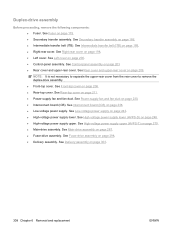
... replacement ENWW NOTE: It is not necessary to separate the upper-rear cover from the rear cover to remove the fuser-drive assembly. ● Front-top cover. See Main-drive assembly on page 175. ● Fuser. See Right-rear cover on page 230. ● Interconnect board (ICB). See Power-supply fan and fan duct on page...
... replacement ENWW NOTE: It is not necessary to separate the upper-rear cover from the rear cover to remove the fuser-drive assembly. ● Front-top cover. See Main-drive assembly on page 175. ● Fuser. See Right-rear cover on page 230. ● Interconnect board (ICB). See Power-supply fan and fan duct on page...
Service Manual
Page 327
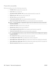
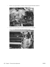
Figure 6-212 Remove the fuser-drive assembly (2 of 6) 2 1 2. Remove two screws (callout 3), and then remove the guide (callout 4). Remove the fuser-drive assembly 1. Figure 6-211 Remove the fuser-drive assembly (1 of 6) 3 4 ENWW Internal assemblies 299 Disconnect one connector (callout 1), and then release the wire harnesses from the guide (callout 2).
Figure 6-212 Remove the fuser-drive assembly (2 of 6) 2 1 2. Remove two screws (callout 3), and then remove the guide (callout 4). Remove the fuser-drive assembly 1. Figure 6-211 Remove the fuser-drive assembly (1 of 6) 3 4 ENWW Internal assemblies 299 Disconnect one connector (callout 1), and then release the wire harnesses from the guide (callout 2).
Service Manual
Page 328
Figure 6-214 Remove the fuser-drive assembly (4 of 6) 6 5 4. Remove one screw (callout 5), and then remove the sheet-metal plate (callout 6). Figure 6-213 Remove the fuser-drive assembly (3 of 6) 8 7 300 Chapter 6 Removal and replacement ENWW 3. Remove one screw (callout 7), and then remove the cover (callout 8).
Figure 6-214 Remove the fuser-drive assembly (4 of 6) 6 5 4. Remove one screw (callout 5), and then remove the sheet-metal plate (callout 6). Figure 6-213 Remove the fuser-drive assembly (3 of 6) 8 7 300 Chapter 6 Removal and replacement ENWW 3. Remove one screw (callout 7), and then remove the cover (callout 8).
Service Manual
Page 329
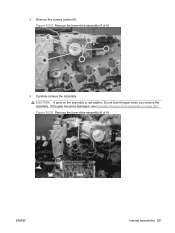
Figure 6-215 Remove the fuser-drive assembly (5 of 6) ENWW Internal assemblies 301 Figure 6-216 Remove the fuser-drive assembly (6 of 6) 9 6. Do not lose the gear when you remove the assembly. If the gear becomes dislodged, see Reinstall the fuser-drive assembly on the assembly is not captive. CAUTION: A gear on page 302. Carefully remove the assembly. 5. Remove five screws (callout 9).
Figure 6-215 Remove the fuser-drive assembly (5 of 6) ENWW Internal assemblies 301 Figure 6-216 Remove the fuser-drive assembly (6 of 6) 9 6. Do not lose the gear when you remove the assembly. If the gear becomes dislodged, see Reinstall the fuser-drive assembly on the assembly is not captive. CAUTION: A gear on page 302. Carefully remove the assembly. 5. Remove five screws (callout 9).
Service Manual
Page 330
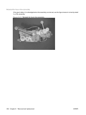
Figure 6-217 Reinstall the fuser-drive assembly 1 302 Chapter 6 Removal and replacement ENWW Reinstall the fuser-drive assembly If the gear (callout 1) is dislodged when the assembly is removed, use the figure below to correctly install it on the assembly.
Figure 6-217 Reinstall the fuser-drive assembly 1 302 Chapter 6 Removal and replacement ENWW Reinstall the fuser-drive assembly If the gear (callout 1) is dislodged when the assembly is removed, use the figure below to correctly install it on the assembly.
Service Manual
Page 331
... High-voltage power supply lower (HVPS-D) on page 298. See Fuser-drive assembly on page 248. ● High-voltage power supply upper. Delivery assembly Before proceeding, remove the following components: ● Fuser. See Secondary transfer assembly on page 211. ● Power-supply fan and fan duct...top cover on page 186. ● Intermediate transfer belt (ITB). See Main-drive assembly on page 198. ● Left cover. See Right-rear cover on page 287. ● Fuser-drive assembly. See Control-panel assembly on page 238. ● Low-voltage power supply. See Interconnect board (...
... High-voltage power supply lower (HVPS-D) on page 298. See Fuser-drive assembly on page 248. ● High-voltage power supply upper. Delivery assembly Before proceeding, remove the following components: ● Fuser. See Secondary transfer assembly on page 211. ● Power-supply fan and fan duct...top cover on page 186. ● Intermediate transfer belt (ITB). See Main-drive assembly on page 198. ● Left cover. See Right-rear cover on page 287. ● Fuser-drive assembly. See Control-panel assembly on page 238. ● Low-voltage power supply. See Interconnect board (...
Service Manual
Page 336
...Rear cover and upper-rear cover. See Control-panel assembly on page 287. ● Fuser-drive assembly. See High-voltage power supply upper (HVPS-T) on page 179. ● Secondary transfer assembly. See Fuser on page 279. ● Main-drive assembly. NOTE: It is not necessary to separate the ...the rear cover to remove the duplex-drive assembly. ● Front-top cover. See Power-supply fan and fan duct on page 298. ● Delivery assembly. See Fuser-drive assembly on page 230. ● Interconnect board (ICB). See Secondary transfer assembly on page 211. ● Power-...
...Rear cover and upper-rear cover. See Control-panel assembly on page 287. ● Fuser-drive assembly. See High-voltage power supply upper (HVPS-T) on page 179. ● Secondary transfer assembly. See Fuser on page 279. ● Main-drive assembly. NOTE: It is not necessary to separate the ...the rear cover to remove the duplex-drive assembly. ● Front-top cover. See Power-supply fan and fan duct on page 298. ● Delivery assembly. See Fuser-drive assembly on page 230. ● Interconnect board (ICB). See Secondary transfer assembly on page 211. ● Power-...
Service Manual
Page 443
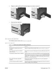
If paper is defective Execute the fuser-motor driving test in the actuator-drive mode. Close the lower right door. Output bin full media sensor is damaged Replace the paper delivery assembly. Poor contact of the fuser-motor (M2) connector Reconnect the connectors of the output bin full sensor (SR6) (J47) ...(SR6) by using the manual sensor test. ENWW Clear paper jams 415 See Delivery assembly on page 353. Poor contact of the output-bin media-full sensor connector Reconnect the connectors of the fuser motor (J117), (J15), and the DC controller PCA (J105). The output-bin media...
If paper is defective Execute the fuser-motor driving test in the actuator-drive mode. Close the lower right door. Output bin full media sensor is damaged Replace the paper delivery assembly. Poor contact of the fuser-motor (M2) connector Reconnect the connectors of the output bin full sensor (SR6) (J47) ...(SR6) by using the manual sensor test. ENWW Clear paper jams 415 See Delivery assembly on page 353. Poor contact of the output-bin media-full sensor connector Reconnect the connectors of the fuser motor (J117), (J15), and the DC controller PCA (J105). The output-bin media...
Service Manual
Page 446
... the sensor monitor mode to verify which sensor detects the media. See Fuser on page 179. ● Loop sensor 1 or 2 (SR14 and SR15): Replace the fuser. The pickup motor is not, replace the cassette-pickup drive assembly. See Pickup motor on page 180. See Pickup roller (Tray 2) on... page 253. See Registration assembly on page 256. 418 Chapter 7 Solve problems ENWW If it is ...
... the sensor monitor mode to verify which sensor detects the media. See Fuser on page 179. ● Loop sensor 1 or 2 (SR14 and SR15): Replace the fuser. The pickup motor is not, replace the cassette-pickup drive assembly. See Pickup motor on page 180. See Pickup roller (Tray 2) on... page 253. See Registration assembly on page 256. 418 Chapter 7 Solve problems ENWW If it is ...

Service Manual
Page 448
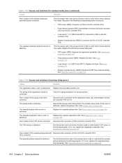
... Cause Solution The duplex re-pickup sensor lever is set correctly. See Duplex-drive assembly on page 179. See Fuser on page 308. The duplex reverse motor is defective Replace the right door assembly. Poor contact of the duplexing reverse-motor Reconnect the connectors of the duplex-...of the duplexing reverse motor (J20) and the connector duplexing driver PCA (J202). If the sensor is defective Replace the duplex drive assembly. The duplex-repick motor is defective, replace the duplexing repick sensor. unhooked 420 Chapter 7 Solve problems ENWW The spring of ...
... Cause Solution The duplex re-pickup sensor lever is set correctly. See Duplex-drive assembly on page 179. See Fuser on page 308. The duplex reverse motor is defective Replace the right door assembly. Poor contact of the duplexing reverse-motor Reconnect the connectors of the duplex-...of the duplexing reverse motor (J20) and the connector duplexing driver PCA (J202). If the sensor is defective Replace the duplex drive assembly. The duplex-repick motor is defective, replace the duplexing repick sensor. unhooked 420 Chapter 7 Solve problems ENWW The spring of ...

Service Manual
Page 523
... Alphabetical parts list (continued) Description Fuser (fixing) 220 V assembly kit Fusing (fixing) connecting cable assembly Fusing (fixing) drive assembly with motor (duplex) Fusing (fixing) drive assembly with motor (simplex) Holder, cartridge lock lever Inner connecting PCA assembly Interlock link Interlock link Interlock link ... cartridge lock Lever, cartridge pressure front Lever, shutter Lifter cable assembly Lifter drive assembly Link, door stopper right Lock, door Lower cartridge guide assembly Lower HVPS-D PCA assembly Part number CC519-67902 RM1-5714-000CN RM1-4974-000CN RM1-5001...
... Alphabetical parts list (continued) Description Fuser (fixing) 220 V assembly kit Fusing (fixing) connecting cable assembly Fusing (fixing) drive assembly with motor (duplex) Fusing (fixing) drive assembly with motor (simplex) Holder, cartridge lock lever Inner connecting PCA assembly Interlock link Interlock link Interlock link ... cartridge lock Lever, cartridge pressure front Lever, shutter Lifter cable assembly Lifter drive assembly Link, door stopper right Lock, door Lower cartridge guide assembly Lower HVPS-D PCA assembly Part number CC519-67902 RM1-5714-000CN RM1-4974-000CN RM1-5001...

Service Manual
Page 528
...assembly (duplex) kit CC468-67916 Secondary transfer assembly (simplex) kit CC468-67917 Scanner assembly kit (one scanner only) CC468-67918 Main drive assembly kit CC468-67920 Front door kit CC519-67901 CC519-67902 CE859-69001 RC2-3983-000CN Fuser (fixing) 110 V assembly kit Fuser (fixing) 220 V assembly kit Formatter assembly... 5) on page 461 Internal components (5 of 5) on page 467 External covers, panels, and doors; on page 455 Fusing assembly on page 483 Fusing assembly on page 483 PCAs on page 485 Internal components (1 of 5) on page 459 Internal components (2 of 5) on page 461...
...assembly (duplex) kit CC468-67916 Secondary transfer assembly (simplex) kit CC468-67917 Scanner assembly kit (one scanner only) CC468-67918 Main drive assembly kit CC468-67920 Front door kit CC519-67901 CC519-67902 CE859-69001 RC2-3983-000CN Fuser (fixing) 110 V assembly kit Fuser (fixing) 220 V assembly kit Formatter assembly... 5) on page 461 Internal components (5 of 5) on page 467 External covers, panels, and doors; on page 455 Fusing assembly on page 483 Fusing assembly on page 483 PCAs on page 485 Internal components (1 of 5) on page 459 Internal components (2 of 5) on page 461...

Service Manual
Page 553
... detection 143, 159 pickup assembly, removing 263 pickup drive assembly, removing 256 pickup operations 140 presence detection 141, 157 tray 2, removing 178 tray 3, removing 178 See also trays certificate of volatility 522 characters, troubleshooting 436 checklists after-service 166 preservice 165 chosen personality not available 383 circuit diagrams fuser temperature-control 116 general 356...
... detection 143, 159 pickup assembly, removing 263 pickup drive assembly, removing 256 pickup operations 140 presence detection 141, 157 tray 2, removing 178 tray 3, removing 178 See also trays certificate of volatility 522 characters, troubleshooting 436 checklists after-service 166 preservice 165 chosen personality not available 383 circuit diagrams fuser temperature-control 116 general 356...

Service Manual
Page 555
... laser safety statement 523 firmware date codes 368 version information 366 firmware, upgrading 97 fixing definition 104 flowcharts troubleshooting 316 fonts included 4 formatter operations 104 PCA, removing 175 resets after replacing 441 security 80 formatter lights 319 fraud hotline 81 fuser cleaning 96 components 115 control-circuit function 115 discrepancy detection 118 drive assembly...
... laser safety statement 523 firmware date codes 368 version information 366 firmware, upgrading 97 fixing definition 104 flowcharts troubleshooting 316 fonts included 4 formatter operations 104 PCA, removing 175 resets after replacing 441 security 80 formatter lights 319 fraud hotline 81 fuser cleaning 96 components 115 control-circuit function 115 discrepancy detection 118 drive assembly...

Service Manual
Page 556
...fuser 115 help, Show Me How menu 14 high-voltage power supply bias generation 112 circuits 112 operations 111 removing, lower 248 removing, upper 279 See also power supply HP Customer Care 514 HP Easy Printer Care opening 71 options 71 using 71 HP fraud hotline 81 HP...connector 4 languages, printer 4 laser safety statements 523 laser/scanner assembly (C/Bk), removing 272 assembly (Y/M), removing 265 failure conditions 120 operations 119 last rotation period 105 latent image formation 122 LEDs. See lights left cover, removing 200 license, software 511 lifter-drive assembly removing 254 light ...
...fuser 115 help, Show Me How menu 14 high-voltage power supply bias generation 112 circuits 112 operations 111 removing, lower 248 removing, upper 279 See also power supply HP Customer Care 514 HP Easy Printer Care opening 71 options 71 using 71 HP fraud hotline 81 HP...connector 4 languages, printer 4 laser safety statements 523 laser/scanner assembly (C/Bk), removing 272 assembly (Y/M), removing 265 failure conditions 120 operations 119 last rotation period 105 latent image formation 122 LEDs. See lights left cover, removing 200 license, software 511 lifter-drive assembly removing 254 light ...

Service Manual
Page 557
... 38 print servers included 2 protocols 32 security 32 settings 32 noise specifications 517 non-HP supplies 81 Novell/NetWare information 367 NVRAM (nonvolatile memory) initialization 443 NVRAM errors 381 ... 113 See also power supply lower right door jams 414 M Macintosh support 514 main-drive assembly removing 287 manual print modes 430 media Show Me How menu 14 supported sizes 44 ...disengagement, removing 251 drum motor 1, removing 283 drum motor 2 or 3, removing 284 failure detection 110 fuser, removing 285 paper feeder 155 pickup, feed, and delivery 137 pickup, removing 253 residual-toner-feed...
... 38 print servers included 2 protocols 32 security 32 settings 32 noise specifications 517 non-HP supplies 81 Novell/NetWare information 367 NVRAM (nonvolatile memory) initialization 443 NVRAM errors 381 ... 113 See also power supply lower right door jams 414 M Macintosh support 514 main-drive assembly removing 287 manual print modes 430 media Show Me How menu 14 supported sizes 44 ...disengagement, removing 251 drum motor 1, removing 283 drum motor 2 or 3, removing 284 failure detection 110 fuser, removing 285 paper feeder 155 pickup, feed, and delivery 137 pickup, removing 253 residual-toner-feed...

Service Manual
Page 559
...215 cassette-pickup assembly 263 cassette-pickup drive assembly 256 cautions for testing 340 troubleshooting 438 printing from Tray 2 55 printing menu 19 problem-solving networks 36 processor speed 3 product info 1 product status HP Easy Printer Care 71 ...fuser 179 fuser motor 285 fuser-drive assembly 298 high-voltage power supply lower 248 high-voltage power supply upper 279 interconnect board (ICB) 238 intermediate transfer belt 188 laser/scanner assembly (C/ Bk) 272 laser/scanner assembly (Y/ M) 265 left cover 200 lifter-drive assembly 254 low-voltage power supply 243 main-drive assembly...
...215 cassette-pickup assembly 263 cassette-pickup drive assembly 256 cautions for testing 340 troubleshooting 438 printing from Tray 2 55 printing menu 19 problem-solving networks 36 processor speed 3 product info 1 product status HP Easy Printer Care 71 ...fuser 179 fuser motor 285 fuser-drive assembly 298 high-voltage power supply lower 248 high-voltage power supply upper 279 interconnect board (ICB) 238 intermediate transfer belt 188 laser/scanner assembly (C/ Bk) 272 laser/scanner assembly (Y/ M) 265 left cover 200 lifter-drive assembly 254 low-voltage power supply 243 main-drive assembly...


