Service Manual
Page 6
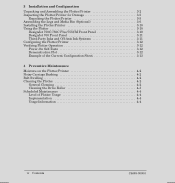
... Assembling the Plotter/Printer 3Ć2 Inspecting the Plotter/Printer for Damage 3Ć5 Repacking the Plotter/Printer 3Ć5 Assembling the Legs and Media Bin (Optional 3Ć6 Installing the Plotter/Printer 3Ć10 Using the Plotter 3Ć10 DesignJet 750C/750C Plus/755CM Front Panel 3Ć10 DesignJet... Plot 3Ć12 Example of the Current Configuration Sheet 3Ć13 4 Preventive Maintenance Moisture on the Plotter/Printer 4Ć2 Noisy Carriage Bushing 4Ć2 Belt Swelling 4Ć2 Cleaning the Plotter 4Ć2 General Cleaning 4Ć2 Cleaning the Drive Roller...
... Assembling the Plotter/Printer 3Ć2 Inspecting the Plotter/Printer for Damage 3Ć5 Repacking the Plotter/Printer 3Ć5 Assembling the Legs and Media Bin (Optional 3Ć6 Installing the Plotter/Printer 3Ć10 Using the Plotter 3Ć10 DesignJet 750C/750C Plus/755CM Front Panel 3Ć10 DesignJet... Plot 3Ć12 Example of the Current Configuration Sheet 3Ć13 4 Preventive Maintenance Moisture on the Plotter/Printer 4Ć2 Noisy Carriage Bushing 4Ć2 Belt Swelling 4Ć2 Cleaning the Plotter 4Ć2 General Cleaning 4Ć2 Cleaning the Drive Roller...

Service Manual
Page 7
...Communications 5Ć2 Plotting 5Ć2 ASICs 5Ć4 Servo Processor 5Ć4 Stepper Motors 5Ć4 Cartridges 5Ć5 Mechanical Overview 5Ć5 CarriageĆAxis Mechanism 5Ć5 Line Sensor 5Ć5 MediaĆAxis Mechanism 5Ć6 Primer Stepper Motor 5Ć6 Bail Stepper Motor 5Ć6... Sensor 5Ć6 Media Sensor 5Ć7 Drop Sensor 5Ć7 PrimerĆCam Sensor 5Ć7 Printed Circuit Assembly (PCA) Overview 5Ć7 Main PCA 5Ć7 Carriage PCA 5Ć8 LineĆSensor PCA 5Ć9 TemperatureĆSensor IC 5Ć9 LinearĆEncoder IC ...
...Communications 5Ć2 Plotting 5Ć2 ASICs 5Ć4 Servo Processor 5Ć4 Stepper Motors 5Ć4 Cartridges 5Ć5 Mechanical Overview 5Ć5 CarriageĆAxis Mechanism 5Ć5 Line Sensor 5Ć5 MediaĆAxis Mechanism 5Ć6 Primer Stepper Motor 5Ć6 Bail Stepper Motor 5Ć6... Sensor 5Ć6 Media Sensor 5Ć7 Drop Sensor 5Ć7 PrimerĆCam Sensor 5Ć7 Printed Circuit Assembly (PCA) Overview 5Ć7 Main PCA 5Ć7 Carriage PCA 5Ć8 LineĆSensor PCA 5Ć9 TemperatureĆSensor IC 5Ć9 LinearĆEncoder IC ...

Service Manual
Page 8
... the Center Cover 6Ć14 Removing the Left Endcover 6Ć16 Removing the Right Endcover 6Ć17 Removing the FrontĆPanel Assembly 6Ć18 Removing the Window Sensor 6Ć20 Removing the PinchĆWheel Sensor 6Ć21 Removing the Media Sensor 6Ć22 Removing...262;Axis Motor Holder 6Ć32 Removing the Cutter 6Ć33 Removing the Cartridge Carriage and Drive Belt 6Ć34 Removing the Trailing Cable 6Ć36 Reinstalling the Trailing Cable 6Ć39 Removing the Starguard Assembly 6Ć40 Removing the Primer 6Ć41 Removing the Service Station 6Ć42...
... the Center Cover 6Ć14 Removing the Left Endcover 6Ć16 Removing the Right Endcover 6Ć17 Removing the FrontĆPanel Assembly 6Ć18 Removing the Window Sensor 6Ć20 Removing the PinchĆWheel Sensor 6Ć21 Removing the Media Sensor 6Ć22 Removing...262;Axis Motor Holder 6Ć32 Removing the Cutter 6Ć33 Removing the Cartridge Carriage and Drive Belt 6Ć34 Removing the Trailing Cable 6Ć36 Reinstalling the Trailing Cable 6Ć39 Removing the Starguard Assembly 6Ć40 Removing the Primer 6Ć41 Removing the Service Station 6Ć42...
Service Manual
Page 11
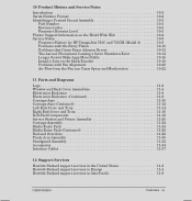
...262;Number Format 10Ć2 Identifying a Printed Circuit Assembly 10Ć3 Part Number 10Ć3 Revision Letter 10Ć3 Firmware Revision Level 10Ć3 Plotter Support Information on the World Wide Web 10Ć4 Service Notes 10Ć5 Firmware History for HP DesignJets 750C and 755CM (Model A 10Ć5 Problems with ...262;14 Right EndĆCover and Trim 11Ć16 RollĆFeed Components 11Ć18 Service Station and Primer Assembly 11Ć20 Carriage Assembly 11Ć22 Media Entry Path 11Ć24 Media Entry Path (Continued 11Ć26 Bail and Overdrive 11Ć28...
...262;Number Format 10Ć2 Identifying a Printed Circuit Assembly 10Ć3 Part Number 10Ć3 Revision Letter 10Ć3 Firmware Revision Level 10Ć3 Plotter Support Information on the World Wide Web 10Ć4 Service Notes 10Ć5 Firmware History for HP DesignJets 750C and 755CM (Model A 10Ć5 Problems with ...262;14 Right EndĆCover and Trim 11Ć16 RollĆFeed Components 11Ć18 Service Station and Primer Assembly 11Ć20 Carriage Assembly 11Ć22 Media Entry Path 11Ć24 Media Entry Path (Continued 11Ć26 Bail and Overdrive 11Ć28...

Service Manual
Page 46
...and the XĆaxis (mediaĆaxis) motor drivers, to manipulate swath data into the registers and sends an interrupt to the carriage ASIC. The main processor then reads the registers, and the interrupt is automatically cleared. D Front panel. D Sensors. ASICs On the...memory (EEROM). D The wiper stepper motor drives the orthogonal wiper. 5-4 Functional Overview C4705-90000 The XĆaxis motor encoder on the carriage assembly. The servo processor controls the: D Servo motors. The processorĆsupport ASIC receives pixels from the plotter sensors. The servo processor ...
...and the XĆaxis (mediaĆaxis) motor drivers, to manipulate swath data into the registers and sends an interrupt to the carriage ASIC. The main processor then reads the registers, and the interrupt is automatically cleared. D Front panel. D Sensors. ASICs On the...memory (EEROM). D The wiper stepper motor drives the orthogonal wiper. 5-4 Functional Overview C4705-90000 The XĆaxis motor encoder on the carriage assembly. The servo processor controls the: D Servo motors. The processorĆsupport ASIC receives pixels from the plotter sensors. The servo processor ...

Service Manual
Page 47
... to fire the cartridges under the plotter's right endcover. The carriage ASIC will receive this signal and fire selected nozzles. WarmĆup When Idle" mode. An optical encoder, located on the carriage assembly, provides positional feedback for banding reduction) using a mark on ...bit per cartridge nozzle), which contains a carriageĆmotor driver. D Circuitry for width measurement). It is working properly. When the carriage motor rotates, it moves the carriage assembly. D Detect media width and skew during media loading. The carriage ASIC controls the firing of the cartridges....
... to fire the cartridges under the plotter's right endcover. The carriage ASIC will receive this signal and fire selected nozzles. WarmĆup When Idle" mode. An optical encoder, located on the carriage assembly, provides positional feedback for banding reduction) using a mark on ...bit per cartridge nozzle), which contains a carriageĆmotor driver. D Circuitry for width measurement). It is working properly. When the carriage motor rotates, it moves the carriage assembly. D Detect media width and skew during media loading. The carriage ASIC controls the firing of the cartridges....

Service Manual
Page 50
...by way of one swath at a time, to a format suitable for storage and sends it is used for the current position of the carriage assembly. The line sensor also provides an edgeĆsensing capability used to fire the cartridges. The main PCA ROM contains the following types of... information: D Variables. D Character sets. D Temporary constants. D When idle. The carriage board also provides feedback to swath RAM by a 12.288ĆMHz, on time, the main PCA reset circuit delays the operation of the cartridge...
...by way of one swath at a time, to a format suitable for storage and sends it is used for the current position of the carriage assembly. The line sensor also provides an edgeĆsensing capability used to fire the cartridges. The main PCA ROM contains the following types of... information: D Variables. D Character sets. D Temporary constants. D When idle. The carriage board also provides feedback to swath RAM by a 12.288ĆMHz, on time, the main PCA reset circuit delays the operation of the cartridge...

Service Manual
Page 51
... dual voltage regulators on Ćboard line driver. PWM Signals The main board contains the drivers for mechanical tolerances as well as the carriage assembly moves along the encoder strip. C4705-90000 Functional Overview 5-9 It is used to measure ambient temperature in the PCA near the print heads...out of the media. LineĆSensor PCA The lineĆsensor PCA is used to calibrate the writing system for the media and carriage motors. It communicates with a unity conjugate ratio system directs the light from the processorĆsupport ASIC. A green and blue LED illuminates...
... dual voltage regulators on Ćboard line driver. PWM Signals The main board contains the drivers for mechanical tolerances as well as the carriage assembly moves along the encoder strip. C4705-90000 Functional Overview 5-9 It is used to measure ambient temperature in the PCA near the print heads...out of the media. LineĆSensor PCA The lineĆsensor PCA is used to calibrate the writing system for the media and carriage motors. It communicates with a unity conjugate ratio system directs the light from the processorĆsupport ASIC. A green and blue LED illuminates...

Service Manual
Page 80
7 Carefully pull the encoder strip through and out of the carriage assembly. 8 Lay the encoder strip on a flat surface. Reinstalling: See following procedure. 6-28 Removal and Replacement C4705-90000
7 Carefully pull the encoder strip through and out of the carriage assembly. 8 Lay the encoder strip on a flat surface. Reinstalling: See following procedure. 6-28 Removal and Replacement C4705-90000

Service Manual
Page 81
Reinstalling the Encoder Strip 1 Ensure that the metallic tensioner is oriented with the transparent area down. 2 Feed the strip through the apertures in the holder. Removal and Replacement 6-29 Tx 10 4 Use a washer and screw to attach the encoder strip to the bracket on the right side of the plotter. 5,5 mm C4705-90000 Ensure that the encoder strip is correctly positioned in the cartridgeĆcarriage assembly. 3 Use a washer and screw to attach the encoder strip to the bracket on the left side of the plotter.
Reinstalling the Encoder Strip 1 Ensure that the metallic tensioner is oriented with the transparent area down. 2 Feed the strip through the apertures in the holder. Removal and Replacement 6-29 Tx 10 4 Use a washer and screw to attach the encoder strip to the bracket on the right side of the plotter. 5,5 mm C4705-90000 Ensure that the encoder strip is correctly positioned in the cartridgeĆcarriage assembly. 3 Use a washer and screw to attach the encoder strip to the bracket on the left side of the plotter.

Service Manual
Page 85
Reassembling: Ensure that the cutter is over the overdrive blade. C4705-90000 Removal and Replacement 6-33 Removing the Cutter 1 Remove the window ' page 6Ć13. 2 Remove the right endcover ' page 6Ć17. 3 Remove the YĆaxis motor holder ' page 6Ć32. 4 Holding the cutter wheels in towards the center of the cutter carriage assembly, move the cutter assembly to the right and remove it from the front slider bar. 5 Slowly release the wheels to relax the spring tension on the wheel arms and lift the cutter assembly clear of the plotter.
Reassembling: Ensure that the cutter is over the overdrive blade. C4705-90000 Removal and Replacement 6-33 Removing the Cutter 1 Remove the window ' page 6Ć13. 2 Remove the right endcover ' page 6Ć17. 3 Remove the YĆaxis motor holder ' page 6Ć32. 4 Holding the cutter wheels in towards the center of the cutter carriage assembly, move the cutter assembly to the right and remove it from the front slider bar. 5 Slowly release the wheels to relax the spring tension on the wheel arms and lift the cutter assembly clear of the plotter.

Service Manual
Page 87
Calibration: After reassembling the plotter, perform: D Pen alignment test ' page 8Ć40. 12 Separate the rear bushing and spring from the carriage assembly and carefully remove the carriage assembly and main drive belt from the plotter. 13 Remove the drive belt from the carriage assembly. D DropĆdetect calibration ' page 7Ć4. C4705-90000 Removal and Replacement 6-35 D LineĆsensor calibration ' page 7Ć5. D Accuracy calibration ' page 7Ć6.
Calibration: After reassembling the plotter, perform: D Pen alignment test ' page 8Ć40. 12 Separate the rear bushing and spring from the carriage assembly and carefully remove the carriage assembly and main drive belt from the plotter. 13 Remove the drive belt from the carriage assembly. D DropĆdetect calibration ' page 7Ć4. C4705-90000 Removal and Replacement 6-35 D LineĆsensor calibration ' page 7Ć5. D Accuracy calibration ' page 7Ć6.

Service Manual
Page 129
... test failure. D Main PCA ' page 6Ć9. D Check the: D XĆaxis encoder. D Carriage assembly. D Main PCA. Error Code 010030 Problem Description Failed communications between the carriage and main processors. D Carriage assembly ' page 6Ć34. D Encoder cable. Only replace one component at a time and check if the error has gone before replacing another component. Using this procedure...
... test failure. D Main PCA ' page 6Ć9. D Check the: D XĆaxis encoder. D Carriage assembly. D Main PCA. Error Code 010030 Problem Description Failed communications between the carriage and main processors. D Carriage assembly ' page 6Ć34. D Encoder cable. Only replace one component at a time and check if the error has gone before replacing another component. Using this procedure...

Service Manual
Page 137
... is in the correct range. 25 YĆStatic Friction ' page 8Ć46 The purpose of this test is to check the static friction of the carriage assembly at different postions along the YĆaxis. 26 YĆAxis Encoder ' page 8Ć47 The purpose of this test is to check the YĆaxis...
... is in the correct range. 25 YĆStatic Friction ' page 8Ć46 The purpose of this test is to check the static friction of the carriage assembly at different postions along the YĆaxis. 26 YĆAxis Encoder ' page 8Ć47 The purpose of this test is to check the YĆaxis...

Service Manual
Page 144
...The purpose of the following messages, in communicating between the main PCA and the carriage. Only replace one of this procedure you will be able to 6 MainĆCarriage Com" and press Enter. Using this test is displayed on the frontĆ...determine exactly which component failed. 8-26 Troubleshooting C4705-90000 SERVICE TESTS 6 Main-Carriage Com 2 The following components: 1 Main PCA ' page 6Ć9. 2 Carriage assembly ' page 6Ć34. 3 Trailing cable ' page 6Ć36. Perform the mainĆcarriage communication test as each circuit is tested. 1 Testing CPROC COMM" 2...
...The purpose of the following messages, in communicating between the main PCA and the carriage. Only replace one of this procedure you will be able to 6 MainĆCarriage Com" and press Enter. Using this test is displayed on the frontĆ...determine exactly which component failed. 8-26 Troubleshooting C4705-90000 SERVICE TESTS 6 Main-Carriage Com 2 The following components: 1 Main PCA ' page 6Ć9. 2 Carriage assembly ' page 6Ć34. 3 Trailing cable ' page 6Ć36. Perform the mainĆcarriage communication test as each circuit is tested. 1 Testing CPROC COMM" 2...

Service Manual
Page 145
.... Using this test is displayed on the frontĆpanel as follows: 1 In the Service Tests submenu, scroll to 7 Carriage" and press Enter. Carriage The purpose of this procedure you will be able to check the internal circuits of the following messages, in the order listed, are displayed ..." message is displayed on the frontĆpanel. 4 If the test fails, an Error Code is to determine exactly which component failed. SERVICE TESTS 7 Carriage 2 The following components: 1 Carriage assembly ' page 6Ć34. 2 Main PCA ' page 6Ć9. 3 Trailing cable ' page 6Ć36. 7.
.... Using this test is displayed on the frontĆpanel as follows: 1 In the Service Tests submenu, scroll to 7 Carriage" and press Enter. Carriage The purpose of this procedure you will be able to check the internal circuits of the following messages, in the order listed, are displayed ..." message is displayed on the frontĆpanel. 4 If the test fails, an Error Code is to determine exactly which component failed. SERVICE TESTS 7 Carriage 2 The following components: 1 Carriage assembly ' page 6Ć34. 2 Main PCA ' page 6Ć9. 3 Trailing cable ' page 6Ć36. 7.

Service Manual
Page 164
.... A typical Maximum PWM value (#) is too high, then you must lubricate the slider rod. 8-46 Troubleshooting C4705-90000 YĆStatic Friction The purpose of the carriage assembly at different postions along the YĆaxis. If the Maximum PWM value is 22. 25. message is displayed on the frontĆpanel as follows...
.... A typical Maximum PWM value (#) is too high, then you must lubricate the slider rod. 8-46 Troubleshooting C4705-90000 YĆStatic Friction The purpose of the carriage assembly at different postions along the YĆaxis. If the Maximum PWM value is 22. 25. message is displayed on the frontĆpanel as follows...
Service Manual
Page 212
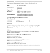
... 1995 Service Note: C3195AĆ03 C3196AĆ03 Supersedes: None Products: HP DesignJet 750C (C3195A) HP DesignJet 750C (C3196A) Serial Numbers: C3195A ESA0000000/ESA5700250 C3196A ESA0000000/ESA5700400 To be performed by: HPĆQualified Personnel Parts Required: Part Number Description Qty C3195Ć60140 Pen Carriage Assembly 1 Situation During very intensive plot workload (high duty cycle), the aerosol...
... 1995 Service Note: C3195AĆ03 C3196AĆ03 Supersedes: None Products: HP DesignJet 750C (C3195A) HP DesignJet 750C (C3196A) Serial Numbers: C3195A ESA0000000/ESA5700250 C3196A ESA0000000/ESA5700400 To be performed by: HPĆQualified Personnel Parts Required: Part Number Description Qty C3195Ć60140 Pen Carriage Assembly 1 Situation During very intensive plot workload (high duty cycle), the aerosol...
Service Manual
Page 234
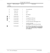
... 19 C4699Ć00016 1 Spring 20 C4705Ć60082 1 Carriage Belt (D/A1Ćsize) C4706Ć60082 1 Carriage Belt (E/A0Ćsize) 21 C4705Ć60054 1 Carriage Assembly (HP DesignJet 700) C3195Ć60143 1 Carriage Assembly (HP DesignJet 750C/750C Plus/755CM) Ć C3195Ć40066 1 Fan Deflector (Only applicable to the EĆsize Printers) For Information regarding this part, refer to Service Note...
... 19 C4699Ć00016 1 Spring 20 C4705Ć60082 1 Carriage Belt (D/A1Ćsize) C4706Ć60082 1 Carriage Belt (E/A0Ćsize) 21 C4705Ć60054 1 Carriage Assembly (HP DesignJet 700) C3195Ć60143 1 Carriage Assembly (HP DesignJet 750C/750C Plus/755CM) Ć C3195Ć40066 1 Fan Deflector (Only applicable to the EĆsize Printers) For Information regarding this part, refer to Service Note...
Service Manual
Page 244
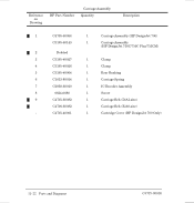
Reference on Drawing HP Part Number Carriage Assembly Quantity Description 1 C4705Ć60054 1 Carriage Assembly (HP DesignJet 700) C3195Ć60143 1 Carriage Assembly (HP DesignJet 750C/750C Plus/755CM) 2 Deleted 3 C3195Ć40027 1 Clamp 4 C3195Ć40026 1 Clamp 5 C3195Ć40064 1 Rear Bushing 6 C1633Ć80014 1 Carriage Spring 7 C2858Ć60010 1 IC Encoder Assembly 8 0624Ć0680 1 Screw 9 C4705Ć60082 1 Carriage Belt (D/A1Ćsize) C4706Ć...
Reference on Drawing HP Part Number Carriage Assembly Quantity Description 1 C4705Ć60054 1 Carriage Assembly (HP DesignJet 700) C3195Ć60143 1 Carriage Assembly (HP DesignJet 750C/750C Plus/755CM) 2 Deleted 3 C3195Ć40027 1 Clamp 4 C3195Ć40026 1 Clamp 5 C3195Ć40064 1 Rear Bushing 6 C1633Ć80014 1 Carriage Spring 7 C2858Ć60010 1 IC Encoder Assembly 8 0624Ć0680 1 Screw 9 C4705Ć60082 1 Carriage Belt (D/A1Ćsize) C4706Ć...


