HP DesignJet 700 user guide
Page 22
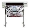
...bits and 1 stop bit. ... For the HP DesignJet 700: You are going to use roll media and print in color. For the HP DesignJet 750C Plus: Load the four color print-cartridges into the carriage on the left ... display and of media supplied, following the instructions on . 2 Load the roll of the plotter's internal plots. Setting Up the Plotter Fast Track 700 750C Plus 700 750C Plus Fast Track If You ...Skip the Rest of This Chapter. 1 Connect the power cord and switch on the label inside the plotter's roll cover. For the HP DesignJet 750C Plus: You are going to use the parallel or ...
...bits and 1 stop bit. ... For the HP DesignJet 700: You are going to use roll media and print in color. For the HP DesignJet 750C Plus: Load the four color print-cartridges into the carriage on the left ... display and of media supplied, following the instructions on . 2 Load the roll of the plotter's internal plots. Setting Up the Plotter Fast Track 700 750C Plus 700 750C Plus Fast Track If You ...Skip the Rest of This Chapter. 1 Connect the power cord and switch on the label inside the plotter's roll cover. For the HP DesignJet 750C Plus: You are going to use the parallel or ...

HP DesignJet 700 user guide
Page 25
...Supplied 1 You need the following items, which were supplied with your plotter should meet the plug requirements for the HP DesignJet 750C Plus) Print cartridge(s): 700 For the HP DesignJet 700: - Power cord The power cord supplied with the plotter. A roll of HP Opaque Bond Paper (for the HP DesignJet...You will need the following items, which were not supplied with the plotter. However, different power cords (international options) are available. Two black 750C Plus For the HP DesignJet 750C Plus: - Two black Not supplied 2 Inspect the plotter itself and the above accessories. ...
...Supplied 1 You need the following items, which were supplied with your plotter should meet the plug requirements for the HP DesignJet 750C Plus) Print cartridge(s): 700 For the HP DesignJet 700: - Power cord The power cord supplied with the plotter. A roll of HP Opaque Bond Paper (for the HP DesignJet...You will need the following items, which were not supplied with the plotter. However, different power cords (international options) are available. Two black 750C Plus For the HP DesignJet 750C Plus: - Two black Not supplied 2 Inspect the plotter itself and the above accessories. ...

HP DesignJet 700 user guide
Page 29
... on the plotter by pushing the power switch. Use only three-wire (earth-grounded) power cords with this plotter. 1 Make sure that the power cord supplied with your plotter matches your power outlet. SETUP 1 1848 If English OK or if you have already changed the language 3 Switch on the ...front of the plotter is OFF. 2 Plug the power cord into the ...
... on the plotter by pushing the power switch. Use only three-wire (earth-grounded) power cords with this plotter. 1 Make sure that the power cord supplied with your plotter matches your power outlet. SETUP 1 1848 If English OK or if you have already changed the language 3 Switch on the ...front of the plotter is OFF. 2 Plug the power cord into the ...

HP DesignJet 700 user guide
Page 115
... To Rotate a Plot from the Front Panel Except in your software. Page format Rotate Full menu mode Default: 0 Affects next plot sent Stays after power off (see page 6-10), and the file contains no raster data. Controlling the Page Format Rotating a Plot Rotating a Plot Rotating a Drawing from the... Panel Your Drawing can only be rotated from the Page format / Rotate option in your software. If you are using the Microsoft Windows driver supplied with this plotter, your files do not contain raster data, and can rotate a plot from the plotter's front panel, without changing the drawing...
... To Rotate a Plot from the Front Panel Except in your software. Page format Rotate Full menu mode Default: 0 Affects next plot sent Stays after power off (see page 6-10), and the file contains no raster data. Controlling the Page Format Rotating a Plot Rotating a Plot Rotating a Drawing from the... Panel Your Drawing can only be rotated from the Page format / Rotate option in your software. If you are using the Microsoft Windows driver supplied with this plotter, your files do not contain raster data, and can rotate a plot from the plotter's front panel, without changing the drawing...

Service Manual
Page 7
...;Sensor IC 5Ć9 LinearĆEncoder IC 5Ć9 Print Control 5Ć9 PWM Signals 5Ć9 FrontĆPanel PCA 5Ć10 Drop Sensor PCA 5Ć10 PowerĆSupply PCA 5Ć10 C4699Ć90000 Contents v
...;Sensor IC 5Ć9 LinearĆEncoder IC 5Ć9 Print Control 5Ć9 PWM Signals 5Ć9 FrontĆPanel PCA 5Ć10 Drop Sensor PCA 5Ć10 PowerĆSupply PCA 5Ć10 C4699Ć90000 Contents v

Service Manual
Page 8
...;Enclosure Cover 6Ć5 Removing a Memory Module (DRAM/ROM SIMM 6Ć7 Reinstalling a Memory Module (DRAM/ROM SIMM 6Ć8 Removing the Main PCA 6Ć9 Removing the PowerĆSupply PCA 6Ć11 Removing the Fan 6Ć12 Removing the Window 6Ć13 Removing the Center Cover 6Ć14 Removing the Left Endcover 6Ć16...
...;Enclosure Cover 6Ć5 Removing a Memory Module (DRAM/ROM SIMM 6Ć7 Reinstalling a Memory Module (DRAM/ROM SIMM 6Ć8 Removing the Main PCA 6Ć9 Removing the PowerĆSupply PCA 6Ć11 Removing the Fan 6Ć12 Removing the Window 6Ć13 Removing the Center Cover 6Ć14 Removing the Left Endcover 6Ć16...
Service Manual
Page 20
Power Requirements HP DesignJet 700, 750C, 750C Plus and 755 CM plotters/printers have a protective earth (ground) terminal. The table below lists the power requirements for the parallel interface. (Cable part numbers ' Service Manual, chapter 11.) 2-2 Site Planning and Requirements C4705-90000 Power Requirements Source ...A 0.60 A 90 to 264 V ac 47-63 Hz Consumption: 140 watts maximum WARNING The ac power outlet (mains) must have selfĆadjusting power supplies and do not require a voltage selector or switch settings prior to use. Parallel (BiĆTronics/Centronics...
Power Requirements HP DesignJet 700, 750C, 750C Plus and 755 CM plotters/printers have a protective earth (ground) terminal. The table below lists the power requirements for the parallel interface. (Cable part numbers ' Service Manual, chapter 11.) 2-2 Site Planning and Requirements C4705-90000 Power Requirements Source ...A 0.60 A 90 to 264 V ac 47-63 Hz Consumption: 140 watts maximum WARNING The ac power outlet (mains) must have selfĆadjusting power supplies and do not require a voltage selector or switch settings prior to use. Parallel (BiĆTronics/Centronics...

Service Manual
Page 45
Electronics Block Diagram BITRONICS RS-232-C FRONT PANEL X-AXIS ENCODER MEDIA SENSOR PINCH WHEEL SENSOR MAIN BOARD X-AXIS SEMNOSOTORR Y-AXIS MOTOR MIO CARD CARÏÏÏÏÏÏRIAGÏÏÏÏÏÏEBOAÏÏÏÏÏÏRD PRIMER STEPPER MOTOR BAIL STEPPER MOTOR WIPER STEPPER MOTOR DROP DETECTOR PRIMER SENSOR POWER SUPPLY FAN C4705-90000 Functional Overview 5-3
Electronics Block Diagram BITRONICS RS-232-C FRONT PANEL X-AXIS ENCODER MEDIA SENSOR PINCH WHEEL SENSOR MAIN BOARD X-AXIS SEMNOSOTORR Y-AXIS MOTOR MIO CARD CARÏÏÏÏÏÏRIAGÏÏÏÏÏÏEBOAÏÏÏÏÏÏRD PRIMER STEPPER MOTOR BAIL STEPPER MOTOR WIPER STEPPER MOTOR DROP DETECTOR PRIMER SENSOR POWER SUPPLY FAN C4705-90000 Functional Overview 5-3
Service Manual
Page 48
In DesignJets 700, 750C Plus and 755CM the media motor has a zero position which ...is indicated to the main PCA. It is controlled by the servo processor and is mounted in the pinchĆarm lift mechanism interrupts the beam of the sensor. 5-6 Functional Overview C4705-90000 The fan is primarily used to cool the power supply...262;plate and connects to the main PCA through the front panel. Fan An internal cooling fan is supplied with a gear at the right end of the plotter's right sideĆplate and is electrically ...
In DesignJets 700, 750C Plus and 755CM the media motor has a zero position which ...is indicated to the main PCA. It is controlled by the servo processor and is mounted in the pinchĆarm lift mechanism interrupts the beam of the sensor. 5-6 Functional Overview C4705-90000 The fan is primarily used to cool the power supply...262;plate and connects to the main PCA through the front panel. Fan An internal cooling fan is supplied with a gear at the right end of the plotter's right sideĆplate and is electrically ...
Service Manual
Page 52
... beam across an aperture which are used for the drop to the processorĆsupport ASIC on the main PCA. PowerĆSupply PCA An autoĆranging power supply is amplified by the preĆamplifier, further amplified by the receiving diode is located in the primary to four ac..., produced by the power supply, are rectified to the VFD and the LEDs and reads the key pad on the main PCA. (Regulated +9 to a pulseĆwidthĆmodulation (PWM), unidirectional current by a photoĆsensitive diode. In order for programming Flash SIMMs on the HP DesignJet 700). The primary ...
... beam across an aperture which are used for the drop to the processorĆsupport ASIC on the main PCA. PowerĆSupply PCA An autoĆranging power supply is amplified by the preĆamplifier, further amplified by the receiving diode is located in the primary to four ac..., produced by the power supply, are rectified to the VFD and the LEDs and reads the key pad on the main PCA. (Regulated +9 to a pulseĆwidthĆmodulation (PWM), unidirectional current by a photoĆsensitive diode. In order for programming Flash SIMMs on the HP DesignJet 700). The primary ...

Service Manual
Page 54
...;Enclosure Cover 6Ć5 Removing a Memory Module (DRAM/ROM SIMM 6Ć7 Reinstalling a Memory Module (DRAM/ROM SIMM 6Ć8 Removing the Main PCA 6Ć9 Removing the PowerĆSupply PCA 6Ć11 Removing the Fan 6Ć12 Removing the Window 6Ć13 Removing the Center Cover 6Ć14 Removing the Left Endcover 6Ć16...
...;Enclosure Cover 6Ć5 Removing a Memory Module (DRAM/ROM SIMM 6Ć7 Reinstalling a Memory Module (DRAM/ROM SIMM 6Ć8 Removing the Main PCA 6Ć9 Removing the PowerĆSupply PCA 6Ć11 Removing the Fan 6Ć12 Removing the Window 6Ć13 Removing the Center Cover 6Ć14 Removing the Left Endcover 6Ć16...

Service Manual
Page 62
... stepper P18 Primer stepper X - 4 Disconnect all cables in the correct orientation and in the order listed: 1. Media motor RAM RAM POST CODE SIMM's connectors M-10 Power supply 5 Remove the eight screws that secure the main PCA to release the cable; First pull the clamp gently towards you connect all cable connectors from...
... stepper P18 Primer stepper X - 4 Disconnect all cables in the correct orientation and in the order listed: 1. Media motor RAM RAM POST CODE SIMM's connectors M-10 Power supply 5 Remove the eight screws that secure the main PCA to release the cable; First pull the clamp gently towards you connect all cable connectors from...

Service Manual
Page 63
Tx 10 dc power-distribution connector ac connector 4 Lift the powerĆsupply PCA clear of the plotter. Removing the PowerĆSupply PCA 1 Remove the electronicsĆenclosure cover ' page 6Ć5. 2 Disconnect the ac connector and the dc powerĆdistribution connector from the powerĆsupply PCA. 3 Remove the screws that attach the powerĆsupply PCA to the electronics enclosure. C4705-90000 Removal and Replacement 6-11
Tx 10 dc power-distribution connector ac connector 4 Lift the powerĆsupply PCA clear of the plotter. Removing the PowerĆSupply PCA 1 Remove the electronicsĆenclosure cover ' page 6Ć5. 2 Disconnect the ac connector and the dc powerĆdistribution connector from the powerĆsupply PCA. 3 Remove the screws that attach the powerĆsupply PCA to the electronics enclosure. C4705-90000 Removal and Replacement 6-11

Service Manual
Page 133
D Causes also include: D A noisy power supply D A bad drop detect sensor D An acoustically noisy environment D The main PCA. 070020 One of the Drop Detection errors has occurred Ć or, during power on the line voltage. D Troubleshoot the cartridges and the drop detector. Corrective Actions D Check for noise on . D Perform the drop detect calibration ' page 7Ć...
D Causes also include: D A noisy power supply D A bad drop detect sensor D An acoustically noisy environment D The main PCA. 070020 One of the Drop Detection errors has occurred Ć or, during power on the line voltage. D Troubleshoot the cartridges and the drop detector. Corrective Actions D Check for noise on . D Perform the drop detect calibration ' page 7Ć...

Service Manual
Page 156
...test is completed, the blk false #/2000" message is displayed on the frontĆpanel. 750C 13 The Testing open sensor in black mode" message is displayed on the frontĆpanel. 750C Plus 14 The Testing open sensor test, then at a time and perform the "Drop Detector" test... D Service Station (which component failed. 8-38 Troubleshooting C4705-90000 Using this procedure you want to perform the open sensor in color mode" message is displayed on the frontĆpanel. D Power Supply PCA ' page 6Ć11. D Main PCA ' page 6Ć9. Only replace one of the drop detector tests fail: 1...
...test is completed, the blk false #/2000" message is displayed on the frontĆpanel. 750C 13 The Testing open sensor in black mode" message is displayed on the frontĆpanel. 750C Plus 14 The Testing open sensor test, then at a time and perform the "Drop Detector" test... D Service Station (which component failed. 8-38 Troubleshooting C4705-90000 Using this procedure you want to perform the open sensor in color mode" message is displayed on the frontĆpanel. D Power Supply PCA ' page 6Ć11. D Main PCA ' page 6Ć9. Only replace one of the drop detector tests fail: 1...

Service Manual
Page 228
Reference on Drawing HP Part Number Electronics Enclosure Quantity Description 1 C4705Ć60092 1 Electronics Enclosure Assembly (D/A1Ćsize) C4706Ć60092 1 Electronics Enclosure Assembly (E/A0Ćsize) 2 Deleted 3 0950Ć2623 1 Power Supply 4 C3190Ć00016 1 Power Supply Insulator 5 0515Ć2200 Ć Screw 6 C3195Ć60149 1 Wiring Harness 7 C3180Ć40012 1 Switch Mount 8 C3195...
Reference on Drawing HP Part Number Electronics Enclosure Quantity Description 1 C4705Ć60092 1 Electronics Enclosure Assembly (D/A1Ćsize) C4706Ć60092 1 Electronics Enclosure Assembly (E/A0Ćsize) 2 Deleted 3 0950Ć2623 1 Power Supply 4 C3190Ć00016 1 Power Supply Insulator 5 0515Ć2200 Ć Screw 6 C3195Ć60149 1 Wiring Harness 7 C3180Ć40012 1 Switch Mount 8 C3195...
Service Manual
Page 279
...;2 Coalescence, 9Ć18 cockle, 9Ć18 code, firmware revision, 10Ć3 color PQ plot, service test, 8Ć34 Configuration Plot, Description, 8Ć56 configuring the plotter, 3Ć12 consumption, power, 2Ć2 controller, DRAM, 5Ć4 copiers, diazo, wearing belt, 8Ć55...262;3 Description Configuration Plot, 8Ć56 PCA, Overview, 5Ć7 description carriage PCA, 5Ć8 line sensor, 5Ć9 main PCA, 5Ć8 power supply PCA, 5Ć10 description of plotter, 1Ć2 Diagnostics - self test, introduction, 8Ć2 diazo copiers, wearing belt, 8Ć55 dimensions, ...
...;2 Coalescence, 9Ć18 cockle, 9Ć18 code, firmware revision, 10Ć3 color PQ plot, service test, 8Ć34 Configuration Plot, Description, 8Ć56 configuring the plotter, 3Ć12 consumption, power, 2Ć2 controller, DRAM, 5Ć4 copiers, diazo, wearing belt, 8Ć55...262;3 Description Configuration Plot, 8Ć56 PCA, Overview, 5Ć7 description carriage PCA, 5Ć8 line sensor, 5Ć9 main PCA, 5Ć8 power supply PCA, 5Ć10 description of plotter, 1Ć2 Diagnostics - self test, introduction, 8Ć2 diazo copiers, wearing belt, 8Ć55 dimensions, ...

Service Manual
Page 282
...Ć4 parallel, interface, 2Ć2 cables, 11Ć37 parity, GlossaryĆ4 parts and diagrams, 11Ć1 PC, GlossaryĆ4 PCA, GlossaryĆ4 Overview, Description, 5Ć7 power supply, description, 5Ć10 PCA (Printed Circuit Assembly) carriage, description, 5Ć8 Main, 5Ć4 Overview, Description, 5Ć7 PCA, identifying a, 10Ć3 PCĆbased diagnostics, 8Ć54...
...Ć4 parallel, interface, 2Ć2 cables, 11Ć37 parity, GlossaryĆ4 parts and diagrams, 11Ć1 PC, GlossaryĆ4 PCA, GlossaryĆ4 Overview, Description, 5Ć7 power supply, description, 5Ć10 PCA (Printed Circuit Assembly) carriage, description, 5Ć8 Main, 5Ć4 Overview, Description, 5Ć7 PCA, identifying a, 10Ć3 PCĆbased diagnostics, 8Ć54...
Service Manual
Page 283
... diagnosis, 9Ć17 CAD 2-D Monochrome, 9Ć13 CAD color diagnostic , 9Ć15 Plotter Languages, 5Ć2 HP/GL2, 5Ć2 RTL, 5Ć2 Sensors, 5Ć4 plotting mode keys, 3Ć10, 3Ć11 PML, 1Ć2 Glossary, GlossaryĆ5 power requirements, 2Ć2 supply, 2Ć2 powerĆsupply PCA, removing, 6Ć11 powerĆsupply autoranging, 5Ć10 PCA, description, 5Ć10 primary, 5Ć...
... diagnosis, 9Ć17 CAD 2-D Monochrome, 9Ć13 CAD color diagnostic , 9Ć15 Plotter Languages, 5Ć2 HP/GL2, 5Ć2 RTL, 5Ć2 Sensors, 5Ć4 plotting mode keys, 3Ć10, 3Ć11 PML, 1Ć2 Glossary, GlossaryĆ5 power requirements, 2Ć2 supply, 2Ć2 powerĆsupply PCA, removing, 6Ć11 powerĆsupply autoranging, 5Ć10 PCA, description, 5Ć10 primary, 5Ć...

Service Manual
Page 284
... sensor, 6Ć22 memory module (DRAM SIMM), 6Ć7 overdrive roller, 6Ć48 pinch arm assemblies, 6Ć57 pinchĆarm sensor, 6Ć21 powerĆsupply PCA, 6Ć11 primer, 6Ć41 right endcover, 6Ć17 rollfeed cover assy, 6Ć51 rollfeed module assemblies, 6Ć52 service station, 6Ć..., 10Ć1 Service Tests, 8Ć17 area fill PQ plot, 8Ć35 bail stepper, 8Ć49 button test, 8Ć53 carriage, 8Ć27 color PQ plot, 8Ć34 cutter, 8Ć48 drop detector, 8Ć37 edge detector, 8Ć39 EEROM, 8Ć21 EEROM clear counters, 8Ć22 EEROM...
... sensor, 6Ć22 memory module (DRAM SIMM), 6Ć7 overdrive roller, 6Ć48 pinch arm assemblies, 6Ć57 pinchĆarm sensor, 6Ć21 powerĆsupply PCA, 6Ć11 primer, 6Ć41 right endcover, 6Ć17 rollfeed cover assy, 6Ć51 rollfeed module assemblies, 6Ć52 service station, 6Ć..., 10Ć1 Service Tests, 8Ć17 area fill PQ plot, 8Ć35 bail stepper, 8Ć49 button test, 8Ć53 carriage, 8Ć27 color PQ plot, 8Ć34 cutter, 8Ć48 drop detector, 8Ć37 edge detector, 8Ć39 EEROM, 8Ć21 EEROM clear counters, 8Ć22 EEROM...


