

Service Manual
Page 9
...-Axis Motor 8-84 Drive Roller 8-86 Gear Assemblies 8-92 Preventive Maintenance 9-1 Moisture on the Printer 9-2 Noisy Carriage Bushing 9-2 Belt Swelling 9-2 Cleaning the Printer 9-2 General Cleaning 9-2 Cleaning the Drive Roller/Print Platen 9-3 Scheduled Maintenance 9-3 Level of Printer Usage 9-3 Scan-Axis Maintenance 9-4 Functional Overview 10-1 Introduction 10-2 SKU Overview 10-2 Electrical System... Ink Delivery System (IDS) 10-7 Ink Supply Station (ISS) 10-7 Tubes Assembly 10-9 Service Station 10-10 Glossary Index Table of Contents HP DesignJets 500 and 800 Series Printers Service Manual 7
...-Axis Motor 8-84 Drive Roller 8-86 Gear Assemblies 8-92 Preventive Maintenance 9-1 Moisture on the Printer 9-2 Noisy Carriage Bushing 9-2 Belt Swelling 9-2 Cleaning the Printer 9-2 General Cleaning 9-2 Cleaning the Drive Roller/Print Platen 9-3 Scheduled Maintenance 9-3 Level of Printer Usage 9-3 Scan-Axis Maintenance 9-4 Functional Overview 10-1 Introduction 10-2 SKU Overview 10-2 Electrical System... Ink Delivery System (IDS) 10-7 Ink Supply Station (ISS) 10-7 Tubes Assembly 10-9 Service Station 10-10 Glossary Index Table of Contents HP DesignJets 500 and 800 Series Printers Service Manual 7

Service Manual
Page 98
... represented as a percentage over the maximum number of Printhead insertions that the Printer is designed to support. Service Tests and Utilities Printer is designed to the Drive Roller. 2 Replace the Carriage Assembly (including the Belt) ⇒ Page 8-78. 3 Replace the Scan-Axis Motor ⇒... as a percentage over the maximum number of times that the Printer is experiencing problems then try the following : 1 Replace the Carriage Assembly ⇒ Page 8-78. 4-28 HP DesignJets 500 and 800 Series Printers Service Manual Number of drops spitted into the Spittoon (on the...
... represented as a percentage over the maximum number of Printhead insertions that the Printer is designed to support. Service Tests and Utilities Printer is designed to the Drive Roller. 2 Replace the Carriage Assembly (including the Belt) ⇒ Page 8-78. 3 Replace the Scan-Axis Motor ⇒... as a percentage over the maximum number of times that the Printer is experiencing problems then try the following : 1 Replace the Carriage Assembly ⇒ Page 8-78. 4-28 HP DesignJets 500 and 800 Series Printers Service Manual Number of drops spitted into the Spittoon (on the...
Service Manual
Page 156
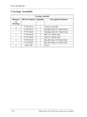
Parts and Diagrams Carriage Assembly Reference on Drawing 1 2 3 4 5 Carriage Assembly HP Part Number Quantity Description/Comments C7769-60151 C7769-60147 C7770-60147 C7769-60182 C7770-60014 C7769-60183 C7770-60013 0624-0769 1 Carriage Assembly 1 Trailing Cable (24" Model Only) 1 Trailing Cable (42" Model Only) 1 Belt (24" Model Only) 1 Belt (42" Model Only) 1 Encoder Strip (24" Model Only) 1 Encoder Strip (42" Model Only) 1 Screw 7-34 HP DesignJets 500 and 800 Series Printers Service Manual
Parts and Diagrams Carriage Assembly Reference on Drawing 1 2 3 4 5 Carriage Assembly HP Part Number Quantity Description/Comments C7769-60151 C7769-60147 C7770-60147 C7769-60182 C7770-60014 C7769-60183 C7770-60013 0624-0769 1 Carriage Assembly 1 Trailing Cable (24" Model Only) 1 Trailing Cable (42" Model Only) 1 Belt (24" Model Only) 1 Belt (42" Model Only) 1 Encoder Strip (24" Model Only) 1 Encoder Strip (42" Model Only) 1 Screw 7-34 HP DesignJets 500 and 800 Series Printers Service Manual
Service Manual
Page 167
... Pinch-Arm Mechanism 8-67 Pinch-Arm Lever 8-69 Pinch-Arm Sensor 8-71 Fork Idler, Tensioner and Idler Pulley 8-74 Encoder Strip 8-76 Carriage Assembly (Including Belt) 8-78 Paper-Axis Motor 8-84 Drive Roller 8-86 Gear Assemblies 8-92 HP DesignJets 500 and 800 Series Printers Service Manual 8-1
... Pinch-Arm Mechanism 8-67 Pinch-Arm Lever 8-69 Pinch-Arm Sensor 8-71 Fork Idler, Tensioner and Idler Pulley 8-74 Encoder Strip 8-76 Carriage Assembly (Including Belt) 8-78 Paper-Axis Motor 8-84 Drive Roller 8-86 Gear Assemblies 8-92 HP DesignJets 500 and 800 Series Printers Service Manual 8-1

Service Manual
Page 195
... Cover - Remove the Power Supply - Disconnect the Scan-Axis Motor Cable from the right hand side of the Belt by pulling the Tensioner down and pushing it into position. HP DesignJets 500 and 800 Series Printers Service Manual 8-29 Refer to lock it towards you to Page 8-27. 4. Release the tension from the Electronics...
... Cover - Remove the Power Supply - Disconnect the Scan-Axis Motor Cable from the right hand side of the Belt by pulling the Tensioner down and pushing it into position. HP DesignJets 500 and 800 Series Printers Service Manual 8-29 Refer to lock it towards you to Page 8-27. 4. Release the tension from the Electronics...

Service Manual
Page 196
Remove the Scan-Axis Motor. 8-30 HP DesignJets 500 and 800 Series Printers Service Manual Remove 2 T-20 screws (Type C) from the Scan-Axis Motor. 7. Remove the left hand side of the Scan-Axis Motor when removing the screws, otherwise the Motor could fall and be damaged. 8. Removal and Installation 6. NOTE Make sure that you keep hold of the Belt from the Scan-Axis Motor.
Remove the Scan-Axis Motor. 8-30 HP DesignJets 500 and 800 Series Printers Service Manual Remove 2 T-20 screws (Type C) from the Scan-Axis Motor. 7. Remove the left hand side of the Scan-Axis Motor when removing the screws, otherwise the Motor could fall and be damaged. 8. Removal and Installation 6. NOTE Make sure that you keep hold of the Belt from the Scan-Axis Motor.
Service Manual
Page 240
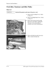
Release the tension from the Scan-Axis Motor on the left hand side. 8-74 HP DesignJets 500 and 800 Series Printers Service Manual Refer to Page 8-5. 2. Refer to Page 8-7. 3. Remove the Left Hand Cover - Release the Belt from the right hand side of the Belt by pulling the Tensioner down and pushing it towards you to lock it into position. 4. Removal and Installation Fork Idler, Tensioner and Idler Pulley Removal WARNING Switch off the printer and remove the power cord. 1. Remove the Right Hand Cover -
Release the tension from the Scan-Axis Motor on the left hand side. 8-74 HP DesignJets 500 and 800 Series Printers Service Manual Refer to Page 8-5. 2. Refer to Page 8-7. 3. Remove the Left Hand Cover - Release the Belt from the right hand side of the Belt by pulling the Tensioner down and pushing it towards you to lock it into position. 4. Removal and Installation Fork Idler, Tensioner and Idler Pulley Removal WARNING Switch off the printer and remove the power cord. 1. Remove the Right Hand Cover -

Service Manual
Page 241
Unlock the Tensioner and remove from the right hand side of the Printer and remove the Idler Pulley. 6. HP DesignJets 500 and 800 Series Printers Service Manual 8-75 NOTE If it is too difficult to unlock the tensioner by hand, try using a Screwdriver (as a lever) instead. Pull out the Belt from the Printer. Removal and Installation 5.
Unlock the Tensioner and remove from the right hand side of the Printer and remove the Idler Pulley. 6. HP DesignJets 500 and 800 Series Printers Service Manual 8-75 NOTE If it is too difficult to unlock the tensioner by hand, try using a Screwdriver (as a lever) instead. Pull out the Belt from the Printer. Removal and Installation 5.

Service Manual
Page 244
... to Page 8-52. 7. Refer to Page 8-7. 4. Removal and Installation Carriage Assembly (Including Belt) Removal 1. Refer to remove the Tubes Assembly from the Carriage. 8-78 HP DesignJets 500 and 800 Series Printers Service Manual Remove the Encoder Strip - NOTE Switch off the Printer after performing this Utility. 2. Manually move the carriage to the correct position to...
... to Page 8-52. 7. Refer to Page 8-7. 4. Removal and Installation Carriage Assembly (Including Belt) Removal 1. Refer to remove the Tubes Assembly from the Carriage. 8-78 HP DesignJets 500 and 800 Series Printers Service Manual Remove the Encoder Strip - NOTE Switch off the Printer after performing this Utility. 2. Manually move the carriage to the correct position to...
Service Manual
Page 248
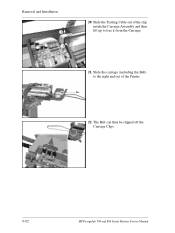
The Belt can then be slipped off the Carriage Clips. 8-82 HP DesignJets 500 and 800 Series Printers Service Manual Removal and Installation 2 1 20. Slide the Trailing Cable out of the Printer. 22. Slide the carriage (including the Belt) to the right and out of the clip inside the Carriage Assembly and then lift up to free it from the Carriage. 21.
The Belt can then be slipped off the Carriage Clips. 8-82 HP DesignJets 500 and 800 Series Printers Service Manual Removal and Installation 2 1 20. Slide the Trailing Cable out of the Printer. 22. Slide the carriage (including the Belt) to the right and out of the clip inside the Carriage Assembly and then lift up to free it from the Carriage. 21.
Service Manual
Page 249
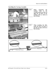
Removal and Installation Installing the Carriage Assembly Align NOTE When connecting the Trailing Cable to the Carriage, make sure that you insert it into the Carriage as shown in this drawing. Scan-Axis Motor Tensioner HP DesignJets 500 and 800 Series Printers Service Manual 8-83 Align NOTE When installing the Belt, make sure that you align the red lines on the Trailing Cable as shown in this drawing.
Removal and Installation Installing the Carriage Assembly Align NOTE When connecting the Trailing Cable to the Carriage, make sure that you insert it into the Carriage as shown in this drawing. Scan-Axis Motor Tensioner HP DesignJets 500 and 800 Series Printers Service Manual 8-83 Align NOTE When installing the Belt, make sure that you align the red lines on the Trailing Cable as shown in this drawing.

Service Manual
Page 261
Preventive Maintenance 9 Moisture on the Printer 9-2 Noisy Carriage Bushing 9-2 Belt Swelling 9-2 Cleaning the Printer 9-2 General Cleaning 9-2 Cleaning the Drive Roller/Print Platen 9-3 Scheduled Maintenance 9-3 Level of Printer Usage 9-3 Scan-Axis Maintenance 9-4 HP DesignJets 500 and 800 Series Printers Service Manual 9-1
Preventive Maintenance 9 Moisture on the Printer 9-2 Noisy Carriage Bushing 9-2 Belt Swelling 9-2 Cleaning the Printer 9-2 General Cleaning 9-2 Cleaning the Drive Roller/Print Platen 9-3 Scheduled Maintenance 9-3 Level of Printer Usage 9-3 Scan-Axis Maintenance 9-4 HP DesignJets 500 and 800 Series Printers Service Manual 9-1
Service Manual
Page 262
... until you need to install them in good operating condition, keep them . Belt Swelling To prevent new belts from swelling incorrectly, keep it again. Preventive Maintenance Preventive Maintenance Moisture on the Printer Users should include the following: 1 Blow away dust accumulation with compressed air ... are determined by the Printer environment and by the types of the carriage, and from moisture condensation, turn the Printer Off, and, using it free of the Printer with a soft lint-free cloth. 9-2 HP DesignJets 500 and 800 Series Printers Service Manual To recover from...
... until you need to install them in good operating condition, keep them . Belt Swelling To prevent new belts from swelling incorrectly, keep it again. Preventive Maintenance Preventive Maintenance Moisture on the Printer Users should include the following: 1 Blow away dust accumulation with compressed air ... are determined by the Printer environment and by the types of the carriage, and from moisture condensation, turn the Printer Off, and, using it free of the Printer with a soft lint-free cloth. 9-2 HP DesignJets 500 and 800 Series Printers Service Manual To recover from...

Service Manual
Page 279
...Index 12 A Advance Calibration 5-9 B Back Platen 8-17 Banding 1-6 Belt 8-78 Belt Swelling 9-2 Boot-Up Sequence 1-12 C Carriage Assembly 8-78 Carriage Movement Test 4-8 Change Cutter 4-24 Change Ink Tubes 4-25 Cleaning Drive Roller 9-3 General 9-2 Print Platen 9-3 Printer 9-2 Color Calibration 5-7 Color differences 1-6 Cover Sensors 1-3 Cutter Assembly 8-32 Cutter Bushing 8-35 Cutter... 2-5 ESD Precautions 8-3 Expiration Message 3-6 F Factory Advance Calibration 5-11 Fork Idler, Tensioner and Idler Pulley 8-74 Formatter 8-20 HP DesignJets 500 and 800 Series Printers Service Manual Index-1
...Index 12 A Advance Calibration 5-9 B Back Platen 8-17 Banding 1-6 Belt 8-78 Belt Swelling 9-2 Boot-Up Sequence 1-12 C Carriage Assembly 8-78 Carriage Movement Test 4-8 Change Cutter 4-24 Change Ink Tubes 4-25 Cleaning Drive Roller 9-3 General 9-2 Print Platen 9-3 Printer 9-2 Color Calibration 5-7 Color differences 1-6 Cover Sensors 1-3 Cutter Assembly 8-32 Cutter Bushing 8-35 Cutter... 2-5 ESD Precautions 8-3 Expiration Message 3-6 F Factory Advance Calibration 5-11 Fork Idler, Tensioner and Idler Pulley 8-74 Formatter 8-20 HP DesignJets 500 and 800 Series Printers Service Manual Index-1
Service Manual
Page 281
... Priming Procedure 1-7 Priming Procedure Fails 1-7 Print Platen 8-56 Print Quality Troubleshooting Checklist 6-2 Printer doesn't power ON 1-3 Printer Information 4-26 Carriage Usage 4-28 Cutter Usage 4-28 Engine Firmware 4-27 Formatter Firmware 4-...Color Accuracy 6-9 Color Consistency 6-9 Cover Sensors 1-3 Line Sensor 1-3 Long Term Color Bleeding 6-9 Vacuum Fan 1-5 Vacuum suction 1-5 R Removing Back Platen 8-17 Carriage Assembly (including Belt) 8-78 Cutter Assembly 8-32 Cutter Bushing 8-35 Cutter Guide 8-55 Cutter Guide Bracket 8-36 Drive Roller 8-86 HP DesignJets 500 and 800 Series Printers...
... Priming Procedure 1-7 Priming Procedure Fails 1-7 Print Platen 8-56 Print Quality Troubleshooting Checklist 6-2 Printer doesn't power ON 1-3 Printer Information 4-26 Carriage Usage 4-28 Cutter Usage 4-28 Engine Firmware 4-27 Formatter Firmware 4-...Color Accuracy 6-9 Color Consistency 6-9 Cover Sensors 1-3 Line Sensor 1-3 Long Term Color Bleeding 6-9 Vacuum Fan 1-5 Vacuum suction 1-5 R Removing Back Platen 8-17 Carriage Assembly (including Belt) 8-78 Cutter Assembly 8-32 Cutter Bushing 8-35 Cutter Guide 8-55 Cutter Guide Bracket 8-36 Drive Roller 8-86 HP DesignJets 500 and 800 Series Printers...


