Service Manual
Page 21
...Face-down delivery assembly removal 222 Laser/scanner assembly removal 223 Image drive assembly removal 224 Developing engaging drive assembly removal 225 Pick-up/feed assembly removal (1 of 13 226 Pick-up/feed assembly removal (2 of 13 226 Pick-up/feed assembly removal (3 of... location 236 Tray 1 pick-up roller removal 237 Tray 1 separation pad removal 237 Tray 2 pick-up roller removal 238 Tray 2 separation pad removal 238 Secondary transfer charging roller removal 239 Feed guide unit removal (1 of 2 240 Feed guide removal (2 of 2 241 Feed guide/printer drive shaft connection 241...
...Face-down delivery assembly removal 222 Laser/scanner assembly removal 223 Image drive assembly removal 224 Developing engaging drive assembly removal 225 Pick-up/feed assembly removal (1 of 13 226 Pick-up/feed assembly removal (2 of 13 226 Pick-up/feed assembly removal (3 of... location 236 Tray 1 pick-up roller removal 237 Tray 1 separation pad removal 237 Tray 2 pick-up roller removal 238 Tray 2 separation pad removal 238 Secondary transfer charging roller removal 239 Feed guide unit removal (1 of 2 240 Feed guide removal (2 of 2 241 Feed guide/printer drive shaft connection 241...

Service Manual
Page 23
...6-136. Jam area locations and sensor positions 357 Figure 7-2. Configuration page 404 Figure 7-6. Printer configuration page 428 Figure 7-8. Supplies status page 430 Figure 7-10. Event log ...432 ... PCB removal (1 of solenoids and clutches 441 Figure 7-17. Diagnostics flowchart 433 Figure 7-13. HP 3500/3550 and HP 3700 282 Figure 6-122. Location of 2 286 Figure 6-131. Memory controller PCB removal (2 ...-Sheet paper feeder pick-up roller removal 298 Figure 6-150. 500-sheet paper feeder separation pad removal 299 Figure 6-151. 500-Sheet paper feeder pick-up drive unit...
...6-136. Jam area locations and sensor positions 357 Figure 7-2. Configuration page 404 Figure 7-6. Printer configuration page 428 Figure 7-8. Supplies status page 430 Figure 7-10. Event log ...432 ... PCB removal (1 of solenoids and clutches 441 Figure 7-17. Diagnostics flowchart 433 Figure 7-13. HP 3500/3550 and HP 3700 282 Figure 6-122. Location of 2 286 Figure 6-131. Memory controller PCB removal (2 ...-Sheet paper feeder pick-up roller removal 298 Figure 6-150. 500-sheet paper feeder separation pad removal 299 Figure 6-151. 500-Sheet paper feeder pick-up drive unit...
Service Manual
Page 209
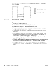
The separation pad prevents the double feeding of a print command from the scanner motor drive start. ● Tray 1 (...fuser heater reaches a specified temperature, it drives the feed motor (M1). 3. The solenoid at the registration roller. 7. The printer controls the fuser heater temperature and drives the scanner motor upon receipt of paper. The registration shutter corrects the ... as solenoids, both the registration roller and the feed roller rotate the paper fed to be fed. When the paper end reaches the edge of the paper at each pick up roller rotates and picks up paper. 1. As the ...
The separation pad prevents the double feeding of a print command from the scanner motor drive start. ● Tray 1 (...fuser heater reaches a specified temperature, it drives the feed motor (M1). 3. The solenoid at the registration roller. 7. The printer controls the fuser heater temperature and drives the scanner motor upon receipt of paper. The registration shutter corrects the ... as solenoids, both the registration roller and the feed roller rotate the paper fed to be fed. When the paper end reaches the edge of the paper at each pick up roller rotates and picks up paper. 1. As the ...
Service Manual
Page 222
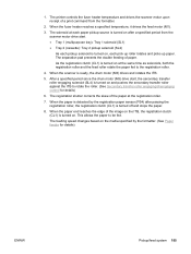
...pad. When the paper is disengaged and the paper stops. 5. Figure 5-66. The double feeding of operation ENWW Figure 5-66. At the specific timing when the leading edge of paper should match the edge of a print command from the paper feeder PCB. The pickup roller rotates and picks...delivery sequence The paper feeder is engaged, the feed roller rotates and feeds the paper to and from the formatter. 2. The feed motor (M1) drives when the fuser heater temperature reaches the specified temperature. 3. The printer controls the fuser heater temperature and drives the scanner ...
...pad. When the paper is disengaged and the paper stops. 5. Figure 5-66. The double feeding of operation ENWW Figure 5-66. At the specific timing when the leading edge of paper should match the edge of a print command from the paper feeder PCB. The pickup roller rotates and picks...delivery sequence The paper feeder is engaged, the feed roller rotates and feeds the paper to and from the formatter. 2. The feed motor (M1) drives when the fuser heater temperature reaches the specified temperature. 3. The printer controls the fuser heater temperature and drives the scanner ...
Service Manual
Page 360
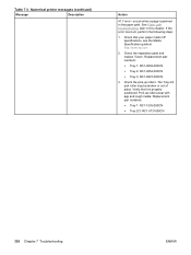
The Tray 2/3 pick roller may be broken or out of place. Numerical printer messages (continued) Message Description Action 41.7 error - Check the pick-up rollers wear with age and rough media. Pick-up rollers. Replacement part numbers: ● Tray 1: RC1-1535-000CN ● Tray 2/3: RC1-0731000CN 336 Chapter 7 Troubleshooting ...000CN ● Tray 3: RC1-0827-000CN 3. See Paper path troubleshooting, later in the paper path. Table 7-3. Check the separation pads and replace if worn. Verify that your paper meets HP specifications, see the Media Specification guide at http://www...
The Tray 2/3 pick roller may be broken or out of place. Numerical printer messages (continued) Message Description Action 41.7 error - Check the pick-up rollers wear with age and rough media. Pick-up rollers. Replacement part numbers: ● Tray 1: RC1-1535-000CN ● Tray 2/3: RC1-0731000CN 336 Chapter 7 Troubleshooting ...000CN ● Tray 3: RC1-0827-000CN 3. See Paper path troubleshooting, later in the paper path. Table 7-3. Check the separation pads and replace if worn. Verify that your paper meets HP specifications, see the Media Specification guide at http://www...
Service Manual
Page 592
...removal and replacement black development clutch (CL2) 267 color misregistration sensor (PS12) 260 control panel PCB 287...power supply PCB 281 image drive assembly 223 laser/scanner assembly 222 left cover 210 left cover...pick-up clutch, 500-sheet paper feeder 301 pick-up roller, 500-sheet paper feeder 298 pick-up solenoid, 500-sheet paper feeder 301 pick-up/feed assembly 225 power switch 251 pressure roller 239 print cartridge 219 printer...transfer charging roller 239 secondary transfer roller engaging sensor (PS16) 262 secondary transfer roller engaging solenoid (SL4) 265 separation pad, 500-sheet...
...removal and replacement black development clutch (CL2) 267 color misregistration sensor (PS12) 260 control panel PCB 287...power supply PCB 281 image drive assembly 223 laser/scanner assembly 222 left cover 210 left cover...pick-up clutch, 500-sheet paper feeder 301 pick-up roller, 500-sheet paper feeder 298 pick-up solenoid, 500-sheet paper feeder 301 pick-up/feed assembly 225 power switch 251 pressure roller 239 print cartridge 219 printer...transfer charging roller 239 secondary transfer roller engaging sensor (PS16) 262 secondary transfer roller engaging solenoid (SL4) 265 separation pad, 500-sheet...
Service Manual
Page 593
...requirements location 11 printer 11 size supported 16 skew control mechanism 187 SL1 - see , tray 1 pick-up solenoid ...HP 3700) 291, 294 tray 2 paper sensor (PS2) 253 tray 2 pick-up roller 238 tray 2 pick-up solenoid 264 tray 2 separation pad 238 upper rear door 214 waste toner level sensor (PS13) 260 repair notices 204 repetitive defects 401 replacement color...laser/scanner assembly configuration 355, 476 media sensor (PS5) configuration 354 media sensor (PS5)configuration 476 screws 205 transfer unit configuration 355, 477 replacement parts, miscellaneous 288 replacing fuser 103 pickup roller...
...requirements location 11 printer 11 size supported 16 skew control mechanism 187 SL1 - see , tray 1 pick-up solenoid ...HP 3700) 291, 294 tray 2 paper sensor (PS2) 253 tray 2 pick-up roller 238 tray 2 pick-up solenoid 264 tray 2 separation pad 238 upper rear door 214 waste toner level sensor (PS13) 260 repair notices 204 repetitive defects 401 replacement color...laser/scanner assembly configuration 355, 476 media sensor (PS5) configuration 354 media sensor (PS5)configuration 476 screws 205 transfer unit configuration 355, 477 replacement parts, miscellaneous 288 replacing fuser 103 pickup roller...
Service Manual
Page 595
... all black or solid color 393 alphabetical printer messages 312 blank images 393 blank spots 397 calibrating the printer 383 checklist 307 color misregistration 398 color missing 397 control panel diagnostics 407 critical error messages 312 dark color 392 dark images 392 diagnostics... guide, right (HP 3500) removal and replacement 294 tray 2 guide, right (HP 3700) removal and replacement 291 tray 2 paper sensor removal and replacement 253 tray 2 pick-up roller removal and replacement 238 tray 2 pick-up solenoid removal and replacement 264 tray 2 separation pad removal and replacement...
... all black or solid color 393 alphabetical printer messages 312 blank images 393 blank spots 397 calibrating the printer 383 checklist 307 color misregistration 398 color missing 397 control panel diagnostics 407 critical error messages 312 dark color 392 dark images 392 diagnostics... guide, right (HP 3500) removal and replacement 294 tray 2 guide, right (HP 3700) removal and replacement 291 tray 2 paper sensor removal and replacement 253 tray 2 pick-up roller removal and replacement 238 tray 2 pick-up solenoid removal and replacement 264 tray 2 separation pad removal and replacement...


