
Service Manual
Page 9
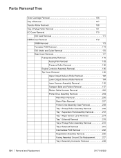
...Laser Scanner Assembly Removal 195 Transport Belts and Rollers Removal 197 Transport Belts and Rollers Replacement 199 Ribbon Cable Harness Removal 202 Printer Drive Assembly Removal 204 Main Motor Removal 206 Motor Plate Removal 207 Printer Drive Assembly Gear Removal 208 Tray 1 Pickup Roller Assembly Removal 209 Tray 1 Separation Pad... Fan Removal 230 Toner Cartridge Guide Removal 232 Tray 1 Removal 234 Tray 1 Pickup Roller Removal 237 Tray 1 Separation Pad Removal 240 DC Bias Voltage Contacts (Leaf Springs) Removal 242 DC Bias Voltage Contacts Replacement 245 Tray 3 Cassette ...
...Laser Scanner Assembly Removal 195 Transport Belts and Rollers Removal 197 Transport Belts and Rollers Replacement 199 Ribbon Cable Harness Removal 202 Printer Drive Assembly Removal 204 Main Motor Removal 206 Motor Plate Removal 207 Printer Drive Assembly Gear Removal 208 Tray 1 Pickup Roller Assembly Removal 209 Tray 1 Separation Pad... Fan Removal 230 Toner Cartridge Guide Removal 232 Tray 1 Removal 234 Tray 1 Pickup Roller Removal 237 Tray 1 Separation Pad Removal 240 DC Bias Voltage Contacts (Leaf Springs) Removal 242 DC Bias Voltage Contacts Replacement 245 Tray 3 Cassette ...
Service Manual
Page 18
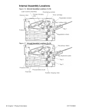
Internal Assembly Locations Figure 1-6 Internal Assembly Locations (1 of 2) Laser scanner assembly Developing cylinder Delivery roller Primary charging roller Toner cartridge Registration shutter Tray 1 pickup roller Fusing film Tray 1 Registration rollers Figure 1-7 Internal Assembly Locations (2 of 2) Tray pickup rollers Tray Separation pads Tray 2 Tray 3 Pressure roller Photosensitive drum Feed belt Transfer charging roller 8 Chapter 1 Product Information C4170-90959
Internal Assembly Locations Figure 1-6 Internal Assembly Locations (1 of 2) Laser scanner assembly Developing cylinder Delivery roller Primary charging roller Toner cartridge Registration shutter Tray 1 pickup roller Fusing film Tray 1 Registration rollers Figure 1-7 Internal Assembly Locations (2 of 2) Tray pickup rollers Tray Separation pads Tray 2 Tray 3 Pressure roller Photosensitive drum Feed belt Transfer charging roller 8 Chapter 1 Product Information C4170-90959
Service Manual
Page 68
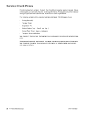
..., environment, and usage conditions. 58 4 Printer Maintenance C4170-90959 Service Check Points Periodic replacement parts are the parts that should be replaced during a regular service visit closest to the end of these parts can cause premature wear of use: • Fusing Assembly • Transfer Roller • Separation Pad • Pickup Rollers (Tray 1, Tray...
..., environment, and usage conditions. 58 4 Printer Maintenance C4170-90959 Service Check Points Periodic replacement parts are the parts that should be replaced during a regular service visit closest to the end of these parts can cause premature wear of use: • Fusing Assembly • Transfer Roller • Separation Pad • Pickup Rollers (Tray 1, Tray...
Service Manual
Page 69
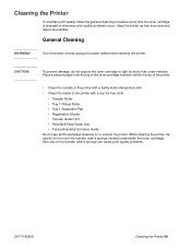
Skin oils on or around the printer. Turn the printer off and unplug the power cable before cleaning the printer. Place a piece of paper over the top of the printer with a dry, lint-free cloth: • Transfer Roller • Tray 1 Pickup Roller • Tray 1 Separation Pad • Registration Shutter • Transfer Guide Unit • Feed Belt/Feed...
Skin oils on or around the printer. Turn the printer off and unplug the power cable before cleaning the printer. Place a piece of paper over the top of the printer with a dry, lint-free cloth: • Transfer Roller • Tray 1 Pickup Roller • Tray 1 Separation Pad • Registration Shutter • Transfer Guide Unit • Feed Belt/Feed...
Service Manual
Page 97
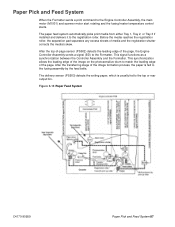
Before the media reaches the registration roller, the separation pad separates any excess sheets of the image on the photosensitive drum to the Formatter. After the transferring stage of the page. After the top-of-page ...
Before the media reaches the registration roller, the separation pad separates any excess sheets of the image on the photosensitive drum to the Formatter. After the transferring stage of the page. After the top-of-page ...
Service Manual
Page 117
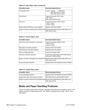
...tray or a failure to move the paper through the input area of the printer. Input Paper Jams Possible Cause Tray Photosensors blocked or inoperative *Pick-up Roller dirty or inoperative (*)Pick-up roller or the separation pad; See "Media Troubleshooting" (page 129) for information about these items are... most likely to be further categorized by the location in the printer in which they occur. The three major areas of the printer are most often related to a ...
...tray or a failure to move the paper through the input area of the printer. Input Paper Jams Possible Cause Tray Photosensors blocked or inoperative *Pick-up Roller dirty or inoperative (*)Pick-up roller or the separation pad; See "Media Troubleshooting" (page 129) for information about these items are... most likely to be further categorized by the location in the printer in which they occur. The three major areas of the printer are most often related to a ...
Service Manual
Page 118
...-000CN (4249 220V) and RG5-4250-000CN Fusing Assembly defective Replace RG5-4132-0000CN (includes PS503) Table 6-8. Input Paper Jams (continued) Possible Cause Recommended Action (*)Separation Pad Inspect / replace TBD(Tray1) RB2-2835-000CN (Tray2) RB2-3008-000CN (Tray3) Feed Rollers Inspect and replace TBD (Tray1) TBD (Tray2) RB2-3490-0000CN(Tray3...
...-000CN (4249 220V) and RG5-4250-000CN Fusing Assembly defective Replace RG5-4132-0000CN (includes PS503) Table 6-8. Input Paper Jams (continued) Possible Cause Recommended Action (*)Separation Pad Inspect / replace TBD(Tray1) RB2-2835-000CN (Tray2) RB2-3008-000CN (Tray3) Feed Rollers Inspect and replace TBD (Tray1) TBD (Tray2) RB2-3490-0000CN(Tray3...
Service Manual
Page 164
... Lower Output Delivery Roller Removal 194 Laser Scanner Assembly Removal 195 Transport Belts and Rollers Removal 197 Ribbon Cable Harness Removal 202 Printer Drive Assembly Removal 204 Main Motor Removal 206 Motor Plate Removal 207 Printer Drive Assembly Gear Removal 208 Tray 1 Pickup Roller Assembly Removal 209 Tray 1 Separation Pad Assembly Removal 212 Tray 1 Paper...
... Lower Output Delivery Roller Removal 194 Laser Scanner Assembly Removal 195 Transport Belts and Rollers Removal 197 Ribbon Cable Harness Removal 202 Printer Drive Assembly Removal 204 Main Motor Removal 206 Motor Plate Removal 207 Printer Drive Assembly Gear Removal 208 Tray 1 Pickup Roller Assembly Removal 209 Tray 1 Separation Pad Assembly Removal 212 Tray 1 Paper...

Service Manual
Page 222
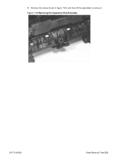
Tray 1 Separation Pad Assembly Removal 1 Remove the following assemblies: • Remove the toner cartridge. (See "Toner Cartridge Removal" (page 156) for instructions. • Remove the DIMM cover. (See "... 1 Removal" (page 234) for instructions.) • Remove the Tray 1 pickup roller assembly. (See "Tray 1 Pickup Roller Assembly Removal" (page 209) for instructions.) 2 To rotate the separation pad forward, simultaneously lift it up and to the left. Figure 7-83Rotating the...
Tray 1 Separation Pad Assembly Removal 1 Remove the following assemblies: • Remove the toner cartridge. (See "Toner Cartridge Removal" (page 156) for instructions. • Remove the DIMM cover. (See "... 1 Removal" (page 234) for instructions.) • Remove the Tray 1 pickup roller assembly. (See "Tray 1 Pickup Roller Assembly Removal" (page 209) for instructions.) 2 To rotate the separation pad forward, simultaneously lift it up and to the left. Figure 7-83Rotating the...
Service Manual
Page 223
Figure 7-84Removing the Separation Pad Assembly C4170-90959 Parts Removal Tree 213 3 Remove the screw shown in figure 7-84, and then lift the assembly to remove it.
Figure 7-84Removing the Separation Pad Assembly C4170-90959 Parts Removal Tree 213 3 Remove the screw shown in figure 7-84, and then lift the assembly to remove it.
Service Manual
Page 247
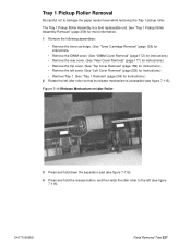
... 1 Pickup Roller Assembly is accessible (see figure 7-116). C4170-90959 Parts Removal Tree 237 Figure 7-115Release Mechanism on Idler Roller 3 Press and hold down the separation pad (see figure 7-116). 4 Press and hold the release button, and then slide the idler roller to damage the paper sensor lever while removing the Tray...
... 1 Pickup Roller Assembly is accessible (see figure 7-116). C4170-90959 Parts Removal Tree 237 Figure 7-115Release Mechanism on Idler Roller 3 Press and hold down the separation pad (see figure 7-116). 4 Press and hold the release button, and then slide the idler roller to damage the paper sensor lever while removing the Tray...
Service Manual
Page 250
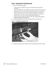
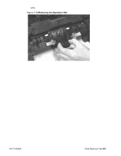
... squeeze both brackets to the left. Tray 1 Separation Pad Removal 1 Remove the following assemblies: • Remove the toner cartridge. (See "Toner Cartridge Removal" (page 156) for instructions. • Remove the DIMM cover. (See "DIMM ... 1 Removal" (page 234) for instructions.) • Remove the Tray 1 pickup roller assembly. (See "Tray 1 Pickup Roller Assembly Removal" (page 209) for instructions.) 2 To rotate the separation pad forward, simultaneously lift it up and to remove the separation pad from the swing 240 7 Removal and Replacement C4170-90959
... squeeze both brackets to the left. Tray 1 Separation Pad Removal 1 Remove the following assemblies: • Remove the toner cartridge. (See "Toner Cartridge Removal" (page 156) for instructions. • Remove the DIMM cover. (See "DIMM ... 1 Removal" (page 234) for instructions.) • Remove the Tray 1 pickup roller assembly. (See "Tray 1 Pickup Roller Assembly Removal" (page 209) for instructions.) 2 To rotate the separation pad forward, simultaneously lift it up and to remove the separation pad from the swing 240 7 Removal and Replacement C4170-90959
Service Manual
Page 251
arms. Figure 7-120Removing the Separation Pad C4170-90959 Parts Removal Tree 241
arms. Figure 7-120Removing the Separation Pad C4170-90959 Parts Removal Tree 241
Service Manual
Page 271
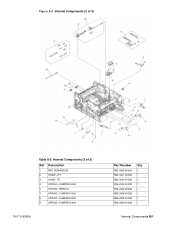
Internal Components (3 of 3) Table 8-5. Figure 8-5 Internal Components (3 of 3) Ref Description 1 PAD, SEPARATION 2 HINGE, LFT 3 HINGE, RT 4 SPRING, COMPRESSION 5 SPRING, TENSION 7 SPRING, COMPRESSION 8 SPRING, COMPRESSION 9 SPRING, COMPRESSION C4170-90959 Part Number RB2-2835-000CN RB2-3041-000CN RB2-3042-000CN RS6-2024-000CN RS6-2030-000CN RB2-2828-000CN RB2-2829-000CN RB2-2845-000CN Qty 1 1 1 1 1 1 1 1 Internal Components 261
Internal Components (3 of 3) Table 8-5. Figure 8-5 Internal Components (3 of 3) Ref Description 1 PAD, SEPARATION 2 HINGE, LFT 3 HINGE, RT 4 SPRING, COMPRESSION 5 SPRING, TENSION 7 SPRING, COMPRESSION 8 SPRING, COMPRESSION 9 SPRING, COMPRESSION C4170-90959 Part Number RB2-2835-000CN RB2-3041-000CN RB2-3042-000CN RS6-2024-000CN RS6-2030-000CN RB2-2828-000CN RB2-2829-000CN RB2-2845-000CN Qty 1 1 1 1 1 1 1 1 Internal Components 261
Service Manual
Page 272
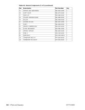
Table 8-5. Internal Components (3 of 3) (continued) Ref Description 10 SPRING, LEAF, GROUNDING 16 SHAFT, IDLER 17 GEAR, 20T 18 HOLDER, SEPARATION PAD 19 ROLLER 20 HOLDER, ROLLER 21 SHAFT 22 SPRING, COMPRESSION 26 PLATE, GROUNDING 30 SPRING, TORSION 32 RING, E 34 GEAR ASSY 35 TRANSPORT BELT KIT ...
Table 8-5. Internal Components (3 of 3) (continued) Ref Description 10 SPRING, LEAF, GROUNDING 16 SHAFT, IDLER 17 GEAR, 20T 18 HOLDER, SEPARATION PAD 19 ROLLER 20 HOLDER, ROLLER 21 SHAFT 22 SPRING, COMPRESSION 26 PLATE, GROUNDING 30 SPRING, TORSION 32 RING, E 34 GEAR ASSY 35 TRANSPORT BELT KIT ...
Service Manual
Page 280
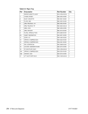
... 2 BODY, CASSETTE 4 PLATE, END 5 ARM, RELEASE, LFT 6 ARM, RELEASE, RT 7 ARM, LOCK 8 ARM, SENSOR 9 PLATE, UPPER LIFTING 9A SHEET, SEPARATION 11 GEAR, 10T 12 SPRING, COMPRESSION 13 SPRING, COMPRESSION 14 PAD, SEPARATION 15 HOLDER, SEPARATION PAD 16 RT SIDE PLATE ASSY 16A SPRING, COMPRESSION 16B SPRING, LEAF 17 LFT SIDE PLATE ASSY Part Number RG5...
... 2 BODY, CASSETTE 4 PLATE, END 5 ARM, RELEASE, LFT 6 ARM, RELEASE, RT 7 ARM, LOCK 8 ARM, SENSOR 9 PLATE, UPPER LIFTING 9A SHEET, SEPARATION 11 GEAR, 10T 12 SPRING, COMPRESSION 13 SPRING, COMPRESSION 14 PAD, SEPARATION 15 HOLDER, SEPARATION PAD 16 RT SIDE PLATE ASSY 16A SPRING, COMPRESSION 16B SPRING, LEAF 17 LFT SIDE PLATE ASSY Part Number RG5...

Service Manual
Page 292
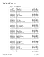
... RF5-2609-000CN RB2-2899-000CN HOLDER, PIN HOLDER, ROLLER RB2-2947-000CN RB2-3047-000CN HOLDER, ROLLER HOLDER, SEPARATION PAD RB2-3485-000CN RB2-2838-000CN HOLDER, SEPARATION PAD IC, TLP1242 RB2-3013-000CN WG8-5382-000CN IC, TLP1242 INTERLOCK SWITCH CABLE WG8-5382-000CN RG5-4256-000CN INTERMEDIATE ...PCB ASSY IR WINDOW` RG5-4250-000CN RB2-2866-000CN LASER-SCANNER ASSY LEFT COVER ASSY RG5-4172-000CN RG5-4139-...
... RF5-2609-000CN RB2-2899-000CN HOLDER, PIN HOLDER, ROLLER RB2-2947-000CN RB2-3047-000CN HOLDER, ROLLER HOLDER, SEPARATION PAD RB2-3485-000CN RB2-2838-000CN HOLDER, SEPARATION PAD IC, TLP1242 RB2-3013-000CN WG8-5382-000CN IC, TLP1242 INTERLOCK SWITCH CABLE WG8-5382-000CN RG5-4256-000CN INTERMEDIATE ...PCB ASSY IR WINDOW` RG5-4250-000CN RB2-2866-000CN LASER-SCANNER ASSY LEFT COVER ASSY RG5-4172-000CN RG5-4139-...
Service Manual
Page 296
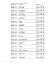
...-2831-000CN GUIDE, CARTRIDGE, RT GUIDE, CARTRIDGE, LFT RB2-2832-000CN RB2-2835-000CN SPRING, COMPRESSION PAD, SEPARATION RB2-2836-000CN RB2-2837-000CN LEVER, SENSOR SPRING, TORSION RB2-2838-000CN RB2-2842-000CN HOLDER, SEPARATION PAD ARM, SENSOR RB2-2843-000CN RB2-2845-000CN SPRING, TORSION SPRING, COMPRESSION RB2-2847-000CN RB2-2849...
...-2831-000CN GUIDE, CARTRIDGE, RT GUIDE, CARTRIDGE, LFT RB2-2832-000CN RB2-2835-000CN SPRING, COMPRESSION PAD, SEPARATION RB2-2836-000CN RB2-2837-000CN LEVER, SENSOR SPRING, TORSION RB2-2838-000CN RB2-2842-000CN HOLDER, SEPARATION PAD ARM, SENSOR RB2-2843-000CN RB2-2845-000CN SPRING, TORSION SPRING, COMPRESSION RB2-2847-000CN RB2-2849...
Service Manual
Page 298
... RB2-3005-000CN ARM, RELEASE, LFT ARM, RELEASE, RT RB2-3007-000CN RB2-3008-000CN SHEET, SEPARATION PAD, SEPARATION RB2-3009-000CN RB2-3010-000CN ARM, LOCK ARM, SENSOR RB2-3012-000CN RB2-3013-000CN SPRING, LEAF HOLDER, SEPARATION PAD RB2-3036-000CN RB2-3037-000CN TRAY, EXPANSION 1 TRAY, EXPANSION 1 RB2-3040-000CN RB2-3041...
... RB2-3005-000CN ARM, RELEASE, LFT ARM, RELEASE, RT RB2-3007-000CN RB2-3008-000CN SHEET, SEPARATION PAD, SEPARATION RB2-3009-000CN RB2-3010-000CN ARM, LOCK ARM, SENSOR RB2-3012-000CN RB2-3013-000CN SPRING, LEAF HOLDER, SEPARATION PAD RB2-3036-000CN RB2-3037-000CN TRAY, EXPANSION 1 TRAY, EXPANSION 1 RB2-3040-000CN RB2-3041...


