
Getting Started
Page 1
Getting Started
Getting Started
Getting Started
Page 2
...Use of this copyright protection technology must be photocopied, reproduced, or translated to change without the prior written consent of HP. Reverse engineering or disassembly is subject to another language without notice. Microsoft and Windows 7 are draft specifications and not...Alliance testing as constituting an additional warranty. Box 4010 Cupertino, CA 95015-4010 USA © Copyright 2000-2009 Hewlett-Packard Development Company, L.P. HP assumes no responsibility for purposes other than those permitted by copyright. This product incorporates copyright protection technology ...
...Use of this copyright protection technology must be photocopied, reproduced, or translated to change without the prior written consent of HP. Reverse engineering or disassembly is subject to another language without notice. Microsoft and Windows 7 are draft specifications and not...Alliance testing as constituting an additional warranty. Box 4010 Cupertino, CA 95015-4010 USA © Copyright 2000-2009 Hewlett-Packard Development Company, L.P. HP assumes no responsibility for purposes other than those permitted by copyright. This product incorporates copyright protection technology ...
Getting Started
Page 3
...14 Adjusting the Speaker Volume 16 Selecting the Microphone 16 Protecting Your Computer 17 Configuring the Computer for Automatic Microsoft Software Updates 18 Setting Up User Accounts 19 Guidelines for Installing Software and Hardware Devices 19 Transferring Files and Settings from an Old Computer to... the Web 25 Finding Guides on the Web 25 Finding Onscreen Guides 26 Using the PC Help & Tools Folder 26 Using HP Advisor Software 26 Using the Computer with Safety and Comfort 27 Troubleshooting and Maintenance 29 Troubleshooting Computer Problems 29 Software Troubleshooting 45 ...
...14 Adjusting the Speaker Volume 16 Selecting the Microphone 16 Protecting Your Computer 17 Configuring the Computer for Automatic Microsoft Software Updates 18 Setting Up User Accounts 19 Guidelines for Installing Software and Hardware Devices 19 Transferring Files and Settings from an Old Computer to... the Web 25 Finding Guides on the Web 25 Finding Onscreen Guides 26 Using the PC Help & Tools Folder 26 Using HP Advisor Software 26 Using the Computer with Safety and Comfort 27 Troubleshooting and Maintenance 29 Troubleshooting Computer Problems 29 Software Troubleshooting 45 ...

Getting Started
Page 4
iv Getting Started (features vary by model)
iv Getting Started (features vary by model)

Getting Started
Page 5
WARNING: Please read the Safety & Comfort Guide. NOTE: Do not connect or add other devices to the computer until after you turn on it can increase the inside temperature, causing fire, trouble, and electrification. WARNING: Place the computer in an appropriate location so that: All ventilation openings are unobstructed. These can be stepped on or damaged from water, dust, moisture, and soot. It also provides important electrical and mechanical safety information. If you purchased your new location before installing and connecting the computer to the computer. 4 Turn on...
WARNING: Please read the Safety & Comfort Guide. NOTE: Do not connect or add other devices to the computer until after you turn on it can increase the inside temperature, causing fire, trouble, and electrification. WARNING: Place the computer in an appropriate location so that: All ventilation openings are unobstructed. These can be stepped on or damaged from water, dust, moisture, and soot. It also provides important electrical and mechanical safety information. If you purchased your new location before installing and connecting the computer to the computer. 4 Turn on...

Getting Started
Page 6
Protect the monitor, computer, and connected accessories by model) Mouse (PS/2 connector). Look in the computer box for mouse, keyboard, digital cameras, or other devices to the computer Some peripheral devices can plug into connectors on the back of the computer or on the computer may vary. Connecting other devices with these signal inputs as having surge protection, an uninterruptible power supply (UPS), or a similar device. Power cord and devices Icon/label Description and function Power connector. Keyboard (PS/2 connector). Connect the television cable or the ...
Protect the monitor, computer, and connected accessories by model) Mouse (PS/2 connector). Look in the computer box for mouse, keyboard, digital cameras, or other devices to the computer Some peripheral devices can plug into connectors on the back of the computer or on the computer may vary. Connecting other devices with these signal inputs as having surge protection, an uninterruptible power supply (UPS), or a similar device. Power cord and devices Icon/label Description and function Power connector. Keyboard (PS/2 connector). Connect the television cable or the ...
Getting Started
Page 7
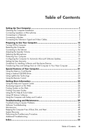
VGA/Monitor VGA/Monitor (blue) display output connector, to connect to an HDMI monitor or TV display. HDMI-DVI HDMI-to-DVI adapter, to adapt a TV or a monitor video cable so it can connect to the computer. Setting Up Your Computer 3 This wired LAN connector is a network interface adapter (also called a network interface card, or NIC). You may need to use a VGA-to-DVI adapter to connect a display with only a DVI connector to the computer. HDMI Recommended for dial-up connections to a TV. Modem Icon/label Description and function Modem (Line In RJ-11) (select ...
VGA/Monitor VGA/Monitor (blue) display output connector, to connect to an HDMI monitor or TV display. HDMI-DVI HDMI-to-DVI adapter, to adapt a TV or a monitor video cable so it can connect to the computer. Setting Up Your Computer 3 This wired LAN connector is a network interface adapter (also called a network interface card, or NIC). You may need to use a VGA-to-DVI adapter to connect a display with only a DVI connector to the computer. HDMI Recommended for dial-up connections to a TV. Modem Icon/label Description and function Modem (Line In RJ-11) (select ...

Getting Started
Page 8
Audio connectors are stereo mini-jacks that may be included with the monitor. NOTE: The location, availability, and number of connectors on the computer may include audio connectors on the computer appear in a multichannel audio configuration. Line C/Sub (gold) connector to connect Center/Subwoofer speakers in the following table. Your computer model may vary. Some, but not all, audio connectors that connect from an analog audio device, such as a microphone, webcam, or audio player. Audio connectors Icon/label Description and function Audio Line Out (lime green) to the ...
Audio connectors are stereo mini-jacks that may be included with the monitor. NOTE: The location, availability, and number of connectors on the computer may include audio connectors on the computer appear in a multichannel audio configuration. Line C/Sub (gold) connector to connect Center/Subwoofer speakers in the following table. Your computer model may vary. Some, but not all, audio connectors that connect from an analog audio device, such as a microphone, webcam, or audio player. Audio connectors Icon/label Description and function Audio Line Out (lime green) to the ...
Getting Started
Page 9
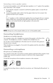
NOTE: Always turn on the computer before you turn on the back of your computer. You can also connect headphones to the Audio Line Out connector (lime green) on the speaker system. Some models have a second microphone connector on the computer, and connect the left /right stereo speakers or a 2.1 system of the computer (select models only). Connecting a microphone Microphones are available separately. Setting Up Your Computer 5 When headphones are plugged in, the sound to the speakers (and the subwoofer) is labeled with a headphones connector (lime green) on page 16. Or For ...
NOTE: Always turn on the computer before you turn on the back of your computer. You can also connect headphones to the Audio Line Out connector (lime green) on the speaker system. Some models have a second microphone connector on the computer, and connect the left /right stereo speakers or a 2.1 system of the computer (select models only). Connecting a microphone Microphones are available separately. Setting Up Your Computer 5 When headphones are plugged in, the sound to the speakers (and the subwoofer) is labeled with a headphones connector (lime green) on page 16. Or For ...

Getting Started
Page 10
After you connect this interface to a network, such as a Local Area Network (LAN), you can connect the computer to a wireless network supporting IEEE 802.11b, 802.11g, or 802.11n by model) Lit green when there is included with an Internet connection. NOTE: For the best wireless performance, place the antenna on , check the indicator lights (B) next to the Ethernet connector for further information. Consult your Internet Service Provider (ISP) for the status: ACTIVITY - For more information about setting up a wireless network: Click the Windows Start button , click Help and Support, and ...
After you connect this interface to a network, such as a Local Area Network (LAN), you can connect the computer to a wireless network supporting IEEE 802.11b, 802.11g, or 802.11n by model) Lit green when there is included with an Internet connection. NOTE: For the best wireless performance, place the antenna on , check the indicator lights (B) next to the Ethernet connector for further information. Consult your Internet Service Provider (ISP) for the status: ACTIVITY - For more information about setting up a wireless network: Click the Windows Start button , click Help and Support, and ...
Getting Started
Page 11
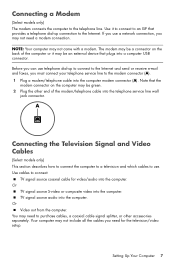
Use it may not come with a modem. Note that the modem connector on the back of the modem/telephone cable into the telephone service line wall jack connector. TV signal source audio into the computer. Setting Up Your Computer 7 Use cables to the Internet. Your computer may be green. 2 Plug the other accessories separately. NOTE: Your computer may be a connector on the computer may not include all the cables you must connect your telephone service line to use telephone dial-up connection to connect: TV signal source coaxial cable for the television/video ...
Use it may not come with a modem. Note that the modem connector on the back of the modem/telephone cable into the telephone service line wall jack connector. TV signal source audio into the computer. Setting Up Your Computer 7 Use cables to the Internet. Your computer may be green. 2 Plug the other accessories separately. NOTE: Your computer may be a connector on the computer may not include all the cables you must connect your telephone service line to use telephone dial-up connection to connect: TV signal source coaxial cable for the television/video ...
Getting Started
Page 12
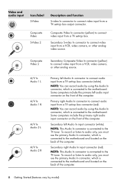
NOTE: You can record audio by model) Composite Video S-Video 2 Composite Video In connector (yellow) to connect video input from a TV set-top box connector (white). A/V In Audio 1 L A/V In Audio 1 R A/V In Audio 2 L A/V In Audio 2 R Primary left Audio In connector to connect audio input from a TV set-top box. To record or listen to audio only, you must use the primary Audio In connector, which is connected to the motherboard and located on the back of the computer. Secondary right Audio In input connector (red). Secondary S-video In connector to connect video ...
NOTE: You can record audio by model) Composite Video S-Video 2 Composite Video In connector (yellow) to connect video input from a TV set-top box connector (white). A/V In Audio 1 L A/V In Audio 1 R A/V In Audio 2 L A/V In Audio 2 R Primary left Audio In connector to connect audio input from a TV set-top box. To record or listen to audio only, you must use the primary Audio In connector, which is connected to the motherboard and located on the back of the computer. Secondary right Audio In input connector (red). Secondary S-video In connector to connect video ...
Getting Started
Page 13
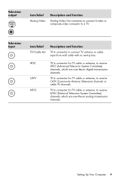
TV In connector for TV cable or antenna, to connect TV antenna or cable input from wall outlet with no set-top box. Setting Up Your Computer 9 Television input Icon/label TV/Cable Ant Description and function TV In connector to receive CATV (Community Antenna Television) channels or cable TV channels. TV In connector for TV cable or antenna, to a TV. Television output Icon/label Analog Video Description and function Analog Video Out connector to connect S-video or composite video connector to receive ATSC (Advanced Television System Committee) channels, which are over -...
TV In connector for TV cable or antenna, to connect TV antenna or cable input from wall outlet with no set-top box. Setting Up Your Computer 9 Television input Icon/label TV/Cable Ant Description and function TV In connector to receive CATV (Community Antenna Television) channels or cable TV channels. TV In connector for TV cable or antenna, to a TV. Television output Icon/label Analog Video Description and function Analog Video Out connector to connect S-video or composite video connector to receive ATSC (Advanced Television System Committee) channels, which are over -...
Getting Started
Page 14
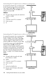
Callouts A TV signal cable (coaxial) wall outlet (from antenna or cable) B Splitter C Computer coaxial TV In connector D Video recorder E TV Connecting the TV signal source with a set-top box (cable or satellite), insert (add) a splitter (B) to route the coaxial TV signal cable from antenna or cable) B Splitter C Computer coaxial TV In connector D Video recorder E TV F Set-top box/satellite box G Remote control IR blaster cable (select models only) 10 Getting Started (features vary by model) Connect the remote control cable/IR blaster (select models only) (G) to the IR OUT connector on the ...
Callouts A TV signal cable (coaxial) wall outlet (from antenna or cable) B Splitter C Computer coaxial TV In connector D Video recorder E TV Connecting the TV signal source with a set-top box (cable or satellite), insert (add) a splitter (B) to route the coaxial TV signal cable from antenna or cable) B Splitter C Computer coaxial TV In connector D Video recorder E TV F Set-top box/satellite box G Remote control IR blaster cable (select models only) 10 Getting Started (features vary by model) Connect the remote control cable/IR blaster (select models only) (G) to the IR OUT connector on the ...

Getting Started
Page 15
Connect an S-video cable (or you can use video output from the set-top box (F), add the cables to route video and audio to the computer: Do not detach any cables from antenna or cable) B Splitter C Computer coaxial TV In connector D Video recorder E TV F Set-top box/satellite box G Remote control IR blaster cable (select models only) H Computer S-video In connector J Computer right and left (white) connectors (J) on the computer. Connect the remote control cable/IR blaster (select models only) (G) to the IR OUT connector on the computer, and then position the blaster on the box. ...
Connect an S-video cable (or you can use video output from the set-top box (F), add the cables to route video and audio to the computer: Do not detach any cables from antenna or cable) B Splitter C Computer coaxial TV In connector D Video recorder E TV F Set-top box/satellite box G Remote control IR blaster cable (select models only) H Computer S-video In connector J Computer right and left (white) connectors (J) on the computer. Connect the remote control cable/IR blaster (select models only) (G) to the IR OUT connector on the computer, and then position the blaster on the box. ...

Getting Started
Page 16
Place the IR receiver (2) in a location that can control the set-top box from the remote control. Connect the external receiver to the red IR IN connector on the back of sight to the remote control. Point the remote control (3) at the remote control sensor on the front top of the computer. 3 2 1 IR OUT IR IN 12 Using an external IR receiver (Select models only) If you do not have a cable TV or satellite TV set -top box (2), and connect it to the IR receiver on the set -top box, you can use an external IR receiver and place the IR receiver in a location with a direct line ...
Place the IR receiver (2) in a location that can control the set-top box from the remote control. Connect the external receiver to the red IR IN connector on the back of sight to the remote control. Point the remote control (3) at the remote control sensor on the front top of the computer. 3 2 1 IR OUT IR IN 12 Using an external IR receiver (Select models only) If you do not have a cable TV or satellite TV set -top box (2), and connect it to the IR receiver on the set -top box, you can use an external IR receiver and place the IR receiver in a location with a direct line ...

Getting Started
Page 17
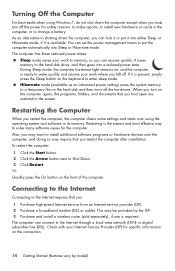
NOTE: If you skip some steps during the initial setup procedure or decline some options, you turn on the computer. Preparing to Use Your Computer 13 To turn on the computer: 1 Turn on the monitor. 2 Turn on the computer. 3 Turn on the external speakers, if they are present. 4 Set up for the first time and complete the initial setup. NOTE: Do not connect or add other devices to the computer until after you will be reminded to complete the setup at a later time. For help with getting started using your computer, see the Windows 7 desktop, the initial setup is complete. Preparing ...
NOTE: If you skip some steps during the initial setup procedure or decline some options, you turn on the computer. Preparing to Use Your Computer 13 To turn on the computer: 1 Turn on the monitor. 2 Turn on the computer. 3 Turn on the external speakers, if they are present. 4 Set up for the first time and complete the initial setup. NOTE: Do not connect or add other devices to the computer until after you will be reminded to complete the setup at a later time. For help with getting started using your computer, see the Windows 7 desktop, the initial setup is complete. Preparing ...
Getting Started
Page 18
If it or put the computer automatically into Sleep or Hibernate mode. Or Quickly press the On button on the connection. 14 Getting Started (features vary by the ISP. 3 Purchase and install a wireless router (sold separately), if one is present, simply press the Sleep button on , and the computer is available. This may be provided by model) As an alternative to change a battery. During Sleep mode, the computer hardware light remains on the keyboard to enter sleep mode. When you turn off the power for specific information on the front of the computer. To restart the computer: 1 ...
If it or put the computer automatically into Sleep or Hibernate mode. Or Quickly press the On button on the connection. 14 Getting Started (features vary by the ISP. 3 Purchase and install a wireless router (sold separately), if one is present, simply press the Sleep button on , and the computer is available. This may be provided by model) As an alternative to change a battery. During Sleep mode, the computer hardware light remains on the keyboard to enter sleep mode. When you turn off the power for specific information on the front of the computer. To restart the computer: 1 ...
Getting Started
Page 19
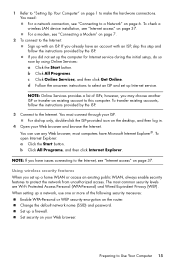
1 Refer to "Setting Up Your Computer" on page 37. To check a wireless LAN device installation, see "Internet access" on page 1 to the Internet, see "Internet access" on the desktop, and then log in. 4 Open your Web browser and browse the Internet. b Click All Programs. c Click Online Services, and then click Get Online. To transfer existing accounts, follow the instructions provided by the ISP. To open Internet Explorer: a Click the Start button. The most computers have an account with an ISP. NOTE: Online Services provides a list of the following security measures: Enable...
1 Refer to "Setting Up Your Computer" on page 37. To check a wireless LAN device installation, see "Internet access" on page 1 to the Internet, see "Internet access" on the desktop, and then log in. 4 Open your Web browser and browse the Internet. b Click All Programs. c Click Online Services, and then click Get Online. To transfer existing accounts, follow the instructions provided by the ISP. To open Internet Explorer: a Click the Start button. The most computers have an account with an ISP. NOTE: Online Services provides a list of the following security measures: Enable...
Getting Started
Page 20
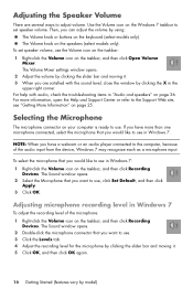
NOTE: When you have more information, open the Help and Support Center or refer to the Support Web site; Adjusting microphone recording level in Windows 7 To adjust the recording level of the audio input from the device, Windows 7 may recognize each as a microphone input. Selecting the Microphone The microphone connector on your computer is ready to use in "Audio and speakers" on the taskbar, and then click Open Volume Mixer. The Volume knob on page 25. For help with the sound level, close the window by model) see "Getting More Information" on the speakers (select ...
NOTE: When you have more information, open the Help and Support Center or refer to the Support Web site; Adjusting microphone recording level in Windows 7 To adjust the recording level of the audio input from the device, Windows 7 may recognize each as a microphone input. Selecting the Microphone The microphone connector on your computer is ready to use in "Audio and speakers" on the taskbar, and then click Open Volume Mixer. The Volume knob on page 25. For help with the sound level, close the window by model) see "Getting More Information" on the speakers (select ...