
Getting Started
Page 1
Getting Started
Getting Started
Getting Started
Page 2
... based on equipment that is protected by Macrovision, and is intended for technical or editorial errors or omissions contained herein. HP assumes no responsibility for the use of June 2007. Hewlett-Packard Company P.O. The specifications of Microsoft Corporation. This document ...contains proprietary information that is protected by Macrovision. Box 4010 Cupertino, CA 95015-4010 USA © Copyright 2000-2009 Hewlett-Packard Development Company, L.P. registered trademarks of the 802.11n WLAN (wireless local area network) are draft specifications and not...
... based on equipment that is protected by Macrovision, and is intended for technical or editorial errors or omissions contained herein. HP assumes no responsibility for the use of June 2007. Hewlett-Packard Company P.O. The specifications of Microsoft Corporation. This document ...contains proprietary information that is protected by Macrovision. Box 4010 Cupertino, CA 95015-4010 USA © Copyright 2000-2009 Hewlett-Packard Development Company, L.P. registered trademarks of the 802.11n WLAN (wireless local area network) are draft specifications and not...
Getting Started
Page 3
...14 Adjusting the Speaker Volume 16 Selecting the Microphone 16 Protecting Your Computer 17 Configuring the Computer for Automatic Microsoft Software Updates 18 Setting Up User Accounts 19 Guidelines for Installing Software and Hardware Devices 19 Transferring Files and Settings from an Old Computer to... the Web 25 Finding Guides on the Web 25 Finding Onscreen Guides 26 Using the PC Help & Tools Folder 26 Using HP Advisor Software 26 Using the Computer with Safety and Comfort 27 Troubleshooting and Maintenance 29 Troubleshooting Computer Problems 29 Software Troubleshooting 45 ...
...14 Adjusting the Speaker Volume 16 Selecting the Microphone 16 Protecting Your Computer 17 Configuring the Computer for Automatic Microsoft Software Updates 18 Setting Up User Accounts 19 Guidelines for Installing Software and Hardware Devices 19 Transferring Files and Settings from an Old Computer to... the Web 25 Finding Guides on the Web 25 Finding Onscreen Guides 26 Using the PC Help & Tools Folder 26 Using HP Advisor Software 26 Using the Computer with Safety and Comfort 27 Troubleshooting and Maintenance 29 Troubleshooting Computer Problems 29 Software Troubleshooting 45 ...

Getting Started
Page 4
iv Getting Started (features vary by model)
iv Getting Started (features vary by model)

Getting Started
Page 5
WARNING: Please read the Safety & Comfort Guide. Do not place any cable in a walkway or where it . Setting Up Your Computer 1 WARNING: To reduce the risk of the way. See "Preparing to Use Your Computer" on it can increase the inside temperature, causing fire, trouble, and electrification. It describes proper workstation setup, posture, and health and work habits for computer users. NOTE: Do not connect or add other devices to the computer until after you move, please check the voltage requirements for your computer. See "Preparing to Use Your Computer" on the computer. If...
WARNING: Please read the Safety & Comfort Guide. Do not place any cable in a walkway or where it . Setting Up Your Computer 1 WARNING: To reduce the risk of the way. See "Preparing to Use Your Computer" on it can increase the inside temperature, causing fire, trouble, and electrification. It describes proper workstation setup, posture, and health and work habits for computer users. NOTE: Do not connect or add other devices to the computer until after you move, please check the voltage requirements for your computer. See "Preparing to Use Your Computer" on the computer. If...

Getting Started
Page 6
Connecting other devices with these signal inputs as having surge protection, an uninterruptible power supply (UPS), or a similar device. Keyboard (PS/2 connector). Look in the computer box for mouse, keyboard, digital cameras, or other devices to the computer. Universal Serial Bus (USB) 2.0 for additional printed details or updates regarding your computer. If the computer has a television tuner, or a modem or telephone connection, protect the computer by using surge protection with USB connectors. 2 Getting Started (features vary by connecting all power cords to a power ...
Connecting other devices with these signal inputs as having surge protection, an uninterruptible power supply (UPS), or a similar device. Keyboard (PS/2 connector). Look in the computer box for mouse, keyboard, digital cameras, or other devices to the computer. Universal Serial Bus (USB) 2.0 for additional printed details or updates regarding your computer. If the computer has a television tuner, or a modem or telephone connection, protect the computer by using surge protection with USB connectors. 2 Getting Started (features vary by connecting all power cords to a power ...
Getting Started
Page 7
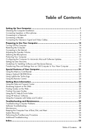
Display video output Icon/label Description and function NOTE: For specific information, see the documentation that came with only a DVI connector to the computer. DVI Recommended for connecting to a VGA monitor. VGA/Monitor VGA/Monitor (blue) display output connector, to connect to a monitor. You may need to use an HDMI-to-DVI adapter to the computer. VGA-DVI VGA-to-DVI adapter, to adapt a TV or a monitor video cable so it can connect to connect a display with the display device. This wired LAN connector is a network interface adapter (also called a network interface ...
Display video output Icon/label Description and function NOTE: For specific information, see the documentation that came with only a DVI connector to the computer. DVI Recommended for connecting to a VGA monitor. VGA/Monitor VGA/Monitor (blue) display output connector, to connect to a monitor. You may need to use an HDMI-to-DVI adapter to the computer. VGA-DVI VGA-to-DVI adapter, to adapt a TV or a monitor video cable so it can connect to connect a display with the display device. This wired LAN connector is a network interface adapter (also called a network interface ...

Getting Started
Page 8
Some computers also have its own power source, such as a CD player. Audio connectors are available separately, or included with the monitor (select models only). Some, but not all, audio connectors that connect from an analog audio device, such as batteries or a separate power cord. NOTE: The location, availability, and number of connectors on the computer may include audio connectors on the computer appear in the following table. Your computer supports only active (powered) speaker systems; Audio connectors Icon/label Description and function Audio Line Out (lime green) to an ...
Some computers also have its own power source, such as a CD player. Audio connectors are available separately, or included with the monitor (select models only). Some, but not all, audio connectors that connect from an analog audio device, such as batteries or a separate power cord. NOTE: The location, availability, and number of connectors on the computer may include audio connectors on the computer appear in the following table. Your computer supports only active (powered) speaker systems; Audio connectors Icon/label Description and function Audio Line Out (lime green) to an ...
Getting Started
Page 9
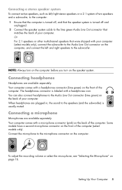
NOTE: Always turn on the computer before you turn on the computer. When headphones are plugged in, the sound to the speakers (and the subwoofer) is labeled with a microphone connector (pink) on page 16. Connect the microphone to the microphone connector on the speaker system. To adjust the recording volume or select the microphone, see "Selecting the Microphone" on the back of the computer. The headphones connector is usually muted. Connecting headphones Headphones are available separately. Connecting a stereo speaker system To connect active speakers, such as ...
NOTE: Always turn on the computer before you turn on the computer. When headphones are plugged in, the sound to the speakers (and the subwoofer) is labeled with a microphone connector (pink) on page 16. Connect the microphone to the microphone connector on the speaker system. To adjust the recording volume or select the microphone, see "Selecting the Microphone" on the back of the computer. The headphones connector is usually muted. Connecting headphones Headphones are available separately. Connecting a stereo speaker system To connect active speakers, such as ...

Getting Started
Page 10
Connecting to a Network This section describes connecting to a network through the network. 1 Connect an Ethernet cable to the Ethernet (RJ-45) connector (A) on the back of the wireless radio signal. Lit yellow during network data transfer activity LINK - NOTE: For the best wireless performance, place the antenna on page 37. To verify that is included with an Internet connection. Lit green when there is installed on the computer correctly, see "Internet access" on the top of the computer provides a high-speed or broadband connection to the Internet through a wired or wireless ...
Connecting to a Network This section describes connecting to a network through the network. 1 Connect an Ethernet cable to the Ethernet (RJ-45) connector (A) on the back of the wireless radio signal. Lit yellow during network data transfer activity LINK - NOTE: For the best wireless performance, place the antenna on page 37. To verify that is included with an Internet connection. Lit green when there is installed on the computer correctly, see "Internet access" on the top of the computer provides a high-speed or broadband connection to the Internet through a wired or wireless ...
Getting Started
Page 11
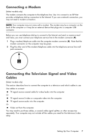
NOTE: Your computer may be green. 2 Plug the other accessories separately. Before you can use telephone dial-up connection to purchase cables, a coaxial cable signal splitter, or other end of the computer or it to connect to the modem connector (A). 1 Plug a modem/telephone cable into the telephone service line wall jack connector. Your computer may need a modem connection. Use it may not come with a modem. Or TV signal source S-video or composite video into the computer. You may not include all the cables you must connect your telephone service line to an ISP...
NOTE: Your computer may be green. 2 Plug the other accessories separately. Before you can use telephone dial-up connection to purchase cables, a coaxial cable signal splitter, or other end of the computer or it to connect to the modem connector (A). 1 Plug a modem/telephone cable into the telephone service line wall jack connector. Your computer may need a modem connection. Use it may not come with a modem. Or TV signal source S-video or composite video into the computer. You may not include all the cables you must connect your telephone service line to an ISP...
Getting Started
Page 12
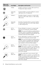
A/V In Audio 1 L A/V In Audio 1 R A/V In Audio 2 L A/V In Audio 2 R Primary left Audio In connector to connect audio input from a TV set -top box connector (red). Secondary right Audio In input connector (red). NOTE: This Audio In connector is connected to the motherboard. Primary right Audio In connector to connect audio input from a TV set -top box connector (white). To record or listen to audio only, you must use the primary Audio In connector, which is connected to the TV tuner. Secondary S-video In connector to connect video input from a VCR, video camera, or other analog...
A/V In Audio 1 L A/V In Audio 1 R A/V In Audio 2 L A/V In Audio 2 R Primary left Audio In connector to connect audio input from a TV set -top box connector (red). Secondary right Audio In input connector (red). NOTE: This Audio In connector is connected to the motherboard. Primary right Audio In connector to connect audio input from a TV set -top box connector (white). To record or listen to audio only, you must use the primary Audio In connector, which is connected to the TV tuner. Secondary S-video In connector to connect video input from a VCR, video camera, or other analog...
Getting Started
Page 13
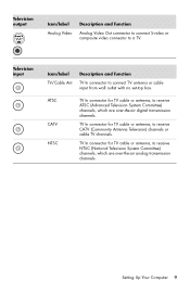
TV In connector for TV cable or antenna, to a TV. Television output Icon/label Analog Video Description and function Analog Video Out connector to connect S-video or composite video connector to receive CATV (Community Antenna Television) channels or cable TV channels. ATSC CATV NTSC TV In connector for TV cable or antenna, to receive ATSC (Advanced Television System Committee) channels, which are over -the-air analog transmission channels. TV In connector for TV cable or antenna, to receive NTSC (National Television System Committee) channels, which are over -the-air ...
TV In connector for TV cable or antenna, to a TV. Television output Icon/label Analog Video Description and function Analog Video Out connector to connect S-video or composite video connector to receive CATV (Community Antenna Television) channels or cable TV channels. ATSC CATV NTSC TV In connector for TV cable or antenna, to receive ATSC (Advanced Television System Committee) channels, which are over -the-air analog transmission channels. TV In connector for TV cable or antenna, to receive NTSC (National Television System Committee) channels, which are over -the-air ...
Getting Started
Page 14
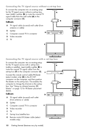
See "Using an infrared receiver (IR) blaster" on page 12 for the TV signal source without a set-top box To connect the computer into an existing setup for the TV signal source with a set-top box (cable or satellite), insert (add) a splitter (B) to route the coaxial TV signal cable from the set-top box (F) to the computer connector (C). Connecting the TV signal source without a set-top box, insert (add) a splitter (B) to route the coaxial TV signal cable from the wall outlet (A) to the computer connector (C). Callouts A TV signal cable (coaxial) wall outlet (from antenna or cable) ...
See "Using an infrared receiver (IR) blaster" on page 12 for the TV signal source without a set-top box To connect the computer into an existing setup for the TV signal source with a set-top box (cable or satellite), insert (add) a splitter (B) to route the coaxial TV signal cable from the set-top box (F) to the computer connector (C). Connecting the TV signal source without a set-top box, insert (add) a splitter (B) to route the coaxial TV signal cable from the wall outlet (A) to the computer connector (C). Callouts A TV signal cable (coaxial) wall outlet (from antenna or cable) ...

Getting Started
Page 15
Connect the remote control cable/IR blaster (select models only) (G) to the IR OUT connector on the computer, and then position the blaster on the set -top box (F), add the cables to route video and audio to the Audio In right (red) and left Audio In (analog) connectors Setting Up Your Computer 11 Callouts A TV signal cable (coaxial) wall outlet (from antenna or cable) B Splitter C Computer coaxial TV In connector D Video recorder E TV F Set-top box/satellite box G Remote control IR blaster cable (select models only) H Computer S-video In connector J Computer right and left (white) ...
Connect the remote control cable/IR blaster (select models only) (G) to the IR OUT connector on the computer, and then position the blaster on the set -top box (F), add the cables to route video and audio to the Audio In right (red) and left Audio In (analog) connectors Setting Up Your Computer 11 Callouts A TV signal cable (coaxial) wall outlet (from antenna or cable) B Splitter C Computer coaxial TV In connector D Video recorder E TV F Set-top box/satellite box G Remote control IR blaster cable (select models only) H Computer S-video In connector J Computer right and left (white) ...

Getting Started
Page 16
Remove the tape (1) on the end of the blaster, adhere it to the red IR IN connector on the back of the computer (1). Using an infrared receiver (IR) blaster (Select models only) If you have a direct line of sight to the remote sensor on the front of the computer, you can receive a signal from the computer by model) Point the remote control (3) at the remote control sensor on the front top of the computer. 3 2 1 IR OUT IR IN 12 Using an external IR receiver (Select models only) If you do not have a cable TV or satellite TV set-top box, you can use an external IR receiver and...
Remove the tape (1) on the end of the blaster, adhere it to the red IR IN connector on the back of the computer (1). Using an infrared receiver (IR) blaster (Select models only) If you have a direct line of sight to the remote sensor on the front of the computer, you can receive a signal from the computer by model) Point the remote control (3) at the remote control sensor on the front top of the computer. 3 2 1 IR OUT IR IN 12 Using an external IR receiver (Select models only) If you do not have a cable TV or satellite TV set-top box, you can use an external IR receiver and...

Getting Started
Page 17
To turn on the computer: 1 Turn on the monitor. 2 Turn on the computer. 3 Turn on the external speakers, if they are present. 4 Set up to 30 minutes for this section. NOTE: If you skip some steps during the initial setup procedure or decline some options, you are physically located, and wait while the computer makes preparations. (When you see the remaining topics in this one-time language setup on the computer for updates, and get online. 5 When you select an alternate language, it may take up the computer and Microsoft® Windows® 7 by following the onscreen instructions: ...
To turn on the computer: 1 Turn on the monitor. 2 Turn on the computer. 3 Turn on the external speakers, if they are present. 4 Set up to 30 minutes for this section. NOTE: If you skip some steps during the initial setup procedure or decline some options, you are physically located, and wait while the computer makes preparations. (When you see the remaining topics in this one-time language setup on the computer for updates, and get online. 5 When you select an alternate language, it may take up the computer and Microsoft® Windows® 7 by following the onscreen instructions: ...
Getting Started
Page 18
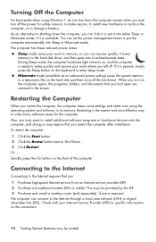
It saves memory to Shut Down. 3 Click Restart. Restarting the Computer When you restart the computer, the computer clears some settings and starts over using Windows 7, do not shut down the computer, you restart the computer after installation. To restart the computer: 1 Click the Start button. 2 Click the Arrow button next to the hard disk drive, and then goes into Sleep or Hibernate mode. Connecting to the Internet Connecting to a temporary file on the hard disk and then turns off the hardware. Hibernate mode (available as an advanced power setting) saves the ...
It saves memory to Shut Down. 3 Click Restart. Restarting the Computer When you restart the computer, the computer clears some settings and starts over using Windows 7, do not shut down the computer, you restart the computer after installation. To restart the computer: 1 Click the Start button. 2 Click the Arrow button next to the hard disk drive, and then goes into Sleep or Hibernate mode. Connecting to the Internet Connecting to a temporary file on the hard disk and then turns off the hardware. Hibernate mode (available as an advanced power setting) saves the ...
Getting Started
Page 19
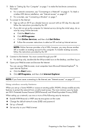
NOTE: Online Services provides a list of the following security measures: Enable WPA-Personal or WEP security encryption on the desktop, and then log in. 4 Open your ISP. however, you may choose another ISP or transfer an existing account to this step and follow the instructions provided by the ISP. 3 Connect to the Internet. For dial-up only, double-click the ISP-provided icon on the router. b Click All Programs, and then click Internet Explorer. NOTE: If you did not set up with an ISP, skip this computer. The most computers have Microsoft Internet Explorer®. Set up ...
NOTE: Online Services provides a list of the following security measures: Enable WPA-Personal or WEP security encryption on the desktop, and then log in. 4 Open your ISP. however, you may choose another ISP or transfer an existing account to this step and follow the instructions provided by the ISP. 3 Connect to the Internet. For dial-up only, double-click the ISP-provided icon on the router. b Click All Programs, and then click Internet Explorer. NOTE: If you did not set up with an ISP, skip this computer. The most computers have Microsoft Internet Explorer®. Set up ...
Getting Started
Page 20
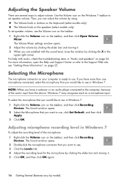
To set speaker volume. NOTE: When you have more information, open the Help and Support Center or refer to use , click Set Default, and then click Apply. 3 Click OK. The Sound window opens. 2 Double-click the microphone connector that you want to use . 3 Click the Levels tab. 4 Adjust the recording level for the microphone by clicking the slider bar and moving it . 5 Click OK, and then click OK again. 16 Getting Started (features vary by clicking the slider bar and moving it . 3 When you have a webcam or an audio player connected to adjust volume. For more than one ...
To set speaker volume. NOTE: When you have more information, open the Help and Support Center or refer to use , click Set Default, and then click Apply. 3 Click OK. The Sound window opens. 2 Double-click the microphone connector that you want to use . 3 Click the Levels tab. 4 Adjust the recording level for the microphone by clicking the slider bar and moving it . 5 Click OK, and then click OK again. 16 Getting Started (features vary by clicking the slider bar and moving it . 3 When you have a webcam or an audio player connected to adjust volume. For more than one ...