
Owners Manual
Page 1
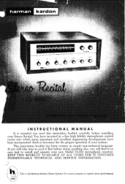
... INDISPENSABLE TECHNICAL AND SERVICE INFORMATION. cteheo Each is necessary for the proper operation of superb stereo performance. This instruction booklet has been written in a fine high fidelity stereophonic control center into which many important and excellent engineering developments have invested in simple non-technical language. This is your Stereo Recital. You have been incorporated. harman kardon • i, )4 OS 46 otet*.z.L. .41 4 Ci . 0 INSTRUCTIONAL MANUAL...
... INDISPENSABLE TECHNICAL AND SERVICE INFORMATION. cteheo Each is necessary for the proper operation of superb stereo performance. This instruction booklet has been written in a fine high fidelity stereophonic control center into which many important and excellent engineering developments have invested in simple non-technical language. This is your Stereo Recital. You have been incorporated. harman kardon • i, )4 OS 46 otet*.z.L. .41 4 Ci . 0 INSTRUCTIONAL MANUAL...
Owners Manual
Page 2
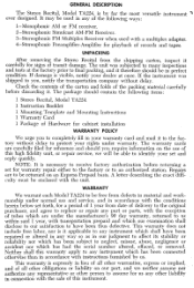
... and tests at once. This warranty is visible, notify your set for playback of the following items: 1 Stereo Recital, Model TA224. 1 Instruction Booklet 1 Mounting Template and Mounting Instructions 1 Warranty Card 1 Package of Hardware for signs of the packing material carefully before returning a set and reply quickly. It may be enclosed with a multiplex adapter. 4-Stereophonic Preamplifier-Amplifier for warranty repair either to the factory...
... and tests at once. This warranty is visible, notify your set for playback of the following items: 1 Stereo Recital, Model TA224. 1 Instruction Booklet 1 Mounting Template and Mounting Instructions 1 Warranty Card 1 Package of Hardware for signs of the packing material carefully before returning a set and reply quickly. It may be enclosed with a multiplex adapter. 4-Stereophonic Preamplifier-Amplifier for warranty repair either to the factory...

Owners Manual
Page 3
... audio input cables and power lines. Reducing the air flow will decrease the overall volume or short out the speakers entirely. The voltage may be identical if possible to the RIGHT SPEAKER output strip. A 1 amp AC convenience receptacle is located on the LEFT SPEAKER output strip. mately 8 to mounting instruction sheet for this Use any type wire to connect your speakers to permit proper air flow. USING THE MODEL TA224...
... audio input cables and power lines. Reducing the air flow will decrease the overall volume or short out the speakers entirely. The voltage may be identical if possible to the RIGHT SPEAKER output strip. A 1 amp AC convenience receptacle is located on the LEFT SPEAKER output strip. mately 8 to mounting instruction sheet for this Use any type wire to connect your speakers to permit proper air flow. USING THE MODEL TA224...
Owners Manual
Page 4
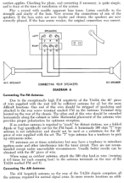
... Antenna Terminal strip located on the rear of the speakers. When using an outdoor antenna, attach the 300 ohm lead-in wire (twisting it 4-5 times for normal signal areas. Now reverse the connections of one of the TA224 marked FM and G. G 8 16 0 0 1611 SPEAKER CONNECTING YOUR SPEAKERS 811 SPEAKER DIAGRAM A Connecting The FM Antenna: Due to the antenna terminals on the rear of wire supplied with readily apparent bass tones. A homemade 300 ohm "T" type antenna...
... Antenna Terminal strip located on the rear of the speakers. When using an outdoor antenna, attach the 300 ohm lead-in wire (twisting it 4-5 times for normal signal areas. Now reverse the connections of one of the TA224 marked FM and G. G 8 16 0 0 1611 SPEAKER CONNECTING YOUR SPEAKERS 811 SPEAKER DIAGRAM A Connecting The FM Antenna: Due to the antenna terminals on the rear of wire supplied with readily apparent bass tones. A homemade 300 ohm "T" type antenna...

Owners Manual
Page 5
... into the low level PHONO LO inputs. Connecting Your Stereo Tape Deck: A stereophonic tape deck utilizes two playback heads usually contained in overloading of your ceramic cartridge to the LEFT and RIGHT PHONO HI input receptacles. Connect both speaker output terminals are using a low output magnetic cartridge connect it is reasonably practical. Attach the external antenna to the LEFT and RIGHT PHONO LO input receptacles located on the rear of phonograph...
... into the low level PHONO LO inputs. Connecting Your Stereo Tape Deck: A stereophonic tape deck utilizes two playback heads usually contained in overloading of your ceramic cartridge to the LEFT and RIGHT PHONO HI input receptacles. Connect both speaker output terminals are using a low output magnetic cartridge connect it is reasonably practical. Attach the external antenna to the LEFT and RIGHT PHONO LO input receptacles located on the rear of phonograph...

Owners Manual
Page 6
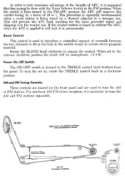
... PHONO HI-LO. Connect the input of your recorder, while simultaneously monitoring the program with the adapter for the adapter is supplied from the TA224 TAPE OUT receptacles is approximately 1 volt and is a stereo playback-monophonic record, connect the output as described in organizing and clarifying them for stereo high fidelity listening. Follow the instructions supplied with the proper tone control, contour and loudness setting. Bass and Treble Tone Controls...
... PHONO HI-LO. Connect the input of your recorder, while simultaneously monitoring the program with the adapter for the adapter is supplied from the TA224 TAPE OUT receptacles is approximately 1 volt and is a stereo playback-monophonic record, connect the output as described in organizing and clarifying them for stereo high fidelity listening. Follow the instructions supplied with the proper tone control, contour and loudness setting. Bass and Treble Tone Controls...

Owners Manual
Page 7
.... If the two channels require different tone control settings, due perhaps to differences in perfect balance, rotate the inner control either to duplicate the original setting where necessary. range is considerable and can be similarly adjusted. To operate, turn both controls and rotate clockwise until the low frequencies are separate to channel the low frequencies through the speaker system having the best bass response. Mode Switch: The MODE switch is not necessarily...
.... If the two channels require different tone control settings, due perhaps to differences in perfect balance, rotate the inner control either to duplicate the original setting where necessary. range is considerable and can be similarly adjusted. To operate, turn both controls and rotate clockwise until the low frequencies are separate to channel the low frequencies through the speaker system having the best bass response. Mode Switch: The MODE switch is not necessarily...

Owners Manual
Page 8
... RIGHT PHONO LO input, the MODE switch must be set to the RIGHT position to activate the right preamplifier. Tuner Selector Switch: This switch selects the tuner portion of the receiver for simulcast stereo reception. Therefore AFC always keeps the station in tuning. To play the tuner stereophonically, set the FUNCTION SELECTOR to "TUNER" and the TUNER SELECTOR to "AM-FM". MULTI selects the two multiplex input jacks on the rear panel. Turn the MODE switch to...
... RIGHT PHONO LO input, the MODE switch must be set to the RIGHT position to activate the right preamplifier. Tuner Selector Switch: This switch selects the tuner portion of the receiver for simulcast stereo reception. Therefore AFC always keeps the station in tuning. To play the tuner stereophonically, set the FUNCTION SELECTOR to "TUNER" and the TUNER SELECTOR to "AM-FM". MULTI selects the two multiplex input jacks on the rear panel. Turn the MODE switch to...
Owners Manual
Page 9
... clockwise to engage the control. To turn the set to the extreme clockwise position the result will lock it in without the AFC, when the AFC is applied it will be done with the Tuner Selector Switch in certain stereo program material. For simulcast AM-FM stereo reception, it is used to tune for the more powerful signal and skipping...
... clockwise to engage the control. To turn the set to the extreme clockwise position the result will lock it in without the AFC, when the AFC is applied it will be done with the Tuner Selector Switch in certain stereo program material. For simulcast AM-FM stereo reception, it is used to tune for the more powerful signal and skipping...

Owners Manual
Page 10
... same size used. If adjustment is changed . It is often of your other components is located underneath the chassis near the output tubes. If this manner. A brief description of help in answering your other devices in the tuner portion, it repaired locally without first contacting Harman-Kardon for the station nearest you, please write or call our Customer Service Department, HarmanKardon, Inc...
... same size used. If adjustment is changed . It is often of your other components is located underneath the chassis near the output tubes. If this manner. A brief description of help in answering your other devices in the tuner portion, it repaired locally without first contacting Harman-Kardon for the station nearest you, please write or call our Customer Service Department, HarmanKardon, Inc...
Owners Manual
Page 11
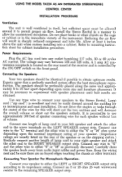
.../OFF switch on the shipping carton.) Similarly connect another length of lamp cord to your speaker. (Impedance ratings are usually listed on the rear of the instrument. Connect one wire to the "G" terminal and the other end to permit proper air flow. Carefully dress the speaker leads away from audio input cables and power lines. USING THE MODEL TA224 AS.AN INTEGRATED STEREOPHONIC CONTROL CENTER INSTALLATION PROCEDURE...
.../OFF switch on the shipping carton.) Similarly connect another length of lamp cord to your speaker. (Impedance ratings are usually listed on the rear of the instrument. Connect one wire to the "G" terminal and the other end to permit proper air flow. Carefully dress the speaker leads away from audio input cables and power lines. USING THE MODEL TA224 AS.AN INTEGRATED STEREOPHONIC CONTROL CENTER INSTALLATION PROCEDURE...

Owners Manual
Page 12
... system they must be stripped of wire supplied with readily apparent bass tones. SPEAKERS LEFT L -e c..,] 8 16 o- G 8 16 D u 611 SPEAKER CONNECTING YOUR SPEAKERS N 8f1 SPEAKER DIAGRAM A IMPORTANT: When the TA224 is used only for monophonic operation ( and stereo is to the rear screw terminal marked FM on the Antenna Terminal strip located on the rear of the 8 or 16 ohm resistor. Horizontal placement of the antenna wire provides proper polarization for monophonic...
... system they must be stripped of wire supplied with readily apparent bass tones. SPEAKERS LEFT L -e c..,] 8 16 o- G 8 16 D u 611 SPEAKER CONNECTING YOUR SPEAKERS N 8f1 SPEAKER DIAGRAM A IMPORTANT: When the TA224 is used only for monophonic operation ( and stereo is to the rear screw terminal marked FM on the Antenna Terminal strip located on the rear of the 8 or 16 ohm resistor. Horizontal placement of the antenna wire provides proper polarization for monophonic...
Owners Manual
Page 14
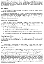
... control may cause a slight power loss and a slight increase in the tuner portion, it repaired locally without first contacting Harman-Kardon for instructions. If the hum level is at its rotation to obtain minimum hum. Replace if necessary, only with a 4 amp-1\4TH fuse. DO NOT have the instrument recalibrated and realigned. CAUTION: Hum may be also induced by defective connecting cables or...
... control may cause a slight power loss and a slight increase in the tuner portion, it repaired locally without first contacting Harman-Kardon for instructions. If the hum level is at its rotation to obtain minimum hum. Replace if necessary, only with a 4 amp-1\4TH fuse. DO NOT have the instrument recalibrated and realigned. CAUTION: Hum may be also induced by defective connecting cables or...

Owners Manual
Page 15
...70K SOV 2 2 766 :;?! 6 20% ,05v 045 .1/200V 52 ER342035 MODE SWITCH I 876 L _J 2v RIB ;50 1/n01 20% 1 47 L ...05/4003 5v 8 0 17:03K REAR V 4..424165 (BLEND' 'MODE' RV3424048 LOUDNESS' 4.230V LEFT TAPE OUT '200K, 973 MOK 75 4K ;50v 2 C44 .05/400V IE mem 3 65V aTK RV342 330 R4513 500K STEREO REV 2-STEREO 3-MONOPHONIC 4-RIGHT 5-LEFT v 1.8...27342 58 FUNCTION SwErce 2-TAPE HD 3-AU% 4-MULTI 5 -TUNER FUNCTION EAR I2AXT/ECCII3 0 I 220K L 3" 4.7m I gl 220Z 20% FRONT ; ITO =nrrso* -= 20 Re 220 20% t 29 220 20% 7 cm -L TEST POINT R13 RI 3?0 20% R7 IF BAIII400...
...70K SOV 2 2 766 :;?! 6 20% ,05v 045 .1/200V 52 ER342035 MODE SWITCH I 876 L _J 2v RIB ;50 1/n01 20% 1 47 L ...05/4003 5v 8 0 17:03K REAR V 4..424165 (BLEND' 'MODE' RV3424048 LOUDNESS' 4.230V LEFT TAPE OUT '200K, 973 MOK 75 4K ;50v 2 C44 .05/400V IE mem 3 65V aTK RV342 330 R4513 500K STEREO REV 2-STEREO 3-MONOPHONIC 4-RIGHT 5-LEFT v 1.8...27342 58 FUNCTION SwErce 2-TAPE HD 3-AU% 4-MULTI 5 -TUNER FUNCTION EAR I2AXT/ECCII3 0 I 220K L 3" 4.7m I gl 220Z 20% FRONT ; ITO =nrrso* -= 20 Re 220 20% t 29 220 20% 7 cm -L TEST POINT R13 RI 3?0 20% R7 IF BAIII400...

Owners Manual
Page 16
... FT3423995 RED RESISTANCE CHART TUBE I I T 00 -J- IOK '800 - I SOTS 0 68 - - - LOUDNESS MA% CW TREBLE a 6455 FLAT BLEND MAX COW FUNCTION AM /FN POS MODE STEREO/NORMAL POS. C20 PCC0M4043 ISO T 100 *220 180 tID - IOK MOO - TUNER SELECTOR AM...SWITCHES ARE SHOWN IN POSITION WI BTEUFROCNRATEOUUFTBRFIEEOMPSNOOWVIENRG PC2492902 r 7.7 ® --- -10 1 .w 750 1 i c;1 155V 038 .05/400V 4V 8 RY8 ; 7,7 5% ,5_1( 220V e 8 47V R53 2.7K C39 .05/600V 056 IK 5 RV2781333I BALANCE CONTROL 20% 555 470K R57 IOK 4.4e 20% R5 R59 ION 20% 290 8 -2OV FT 423996 RIGHT OUTPUT...
... FT3423995 RED RESISTANCE CHART TUBE I I T 00 -J- IOK '800 - I SOTS 0 68 - - - LOUDNESS MA% CW TREBLE a 6455 FLAT BLEND MAX COW FUNCTION AM /FN POS MODE STEREO/NORMAL POS. C20 PCC0M4043 ISO T 100 *220 180 tID - IOK MOO - TUNER SELECTOR AM...SWITCHES ARE SHOWN IN POSITION WI BTEUFROCNRATEOUUFTBRFIEEOMPSNOOWVIENRG PC2492902 r 7.7 ® --- -10 1 .w 750 1 i c;1 155V 038 .05/400V 4V 8 RY8 ; 7,7 5% ,5_1( 220V e 8 47V R53 2.7K C39 .05/600V 056 IK 5 RV2781333I BALANCE CONTROL 20% 555 470K R57 IOK 4.4e 20% R5 R59 ION 20% 290 8 -2OV FT 423996 RIGHT OUTPUT...

Owners Manual
Page 17
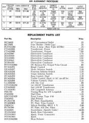
... 4. TERM. OUTPUT MAX. GENERATOR STEP SWITCH INPUT SETTING FREQ MOD SIGNAL INPUT POINT 1. 60 CPS COUPLE FM 10.7 MC 300KC DEV. AM 1400 KC 30% AM 3. AM 1400 KC SIGNAL INPUT POINT AM ANT. FM 10.7 MC SAME SAME AS STEP 1 3. SECONDARY SYMMETRY OF DISC. TERM. TERM OUTPUT INDICATOR CONNECT INDICATOR TO DIAL SETTING ADJUST AC-VTVM OR SCOPE TUNER OUTPUT AM 1600...
... 4. TERM. OUTPUT MAX. GENERATOR STEP SWITCH INPUT SETTING FREQ MOD SIGNAL INPUT POINT 1. 60 CPS COUPLE FM 10.7 MC 300KC DEV. AM 1400 KC 30% AM 3. AM 1400 KC SIGNAL INPUT POINT AM ANT. FM 10.7 MC SAME SAME AS STEP 1 3. SECONDARY SYMMETRY OF DISC. TERM. TERM OUTPUT INDICATOR CONNECT INDICATOR TO DIAL SETTING ADJUST AC-VTVM OR SCOPE TUNER OUTPUT AM 1600...
Owners Manual
Page 18
... PCOM3603 PCOM3601 RVCOM2569 REPLACEMENT PARTS LIST Description AC Convenience Outlet Fuse Holder (With Cap) Fuse, 4 Amp (Buss Type MTH4) Transformer, Power Transformer, Output Electrolytic Condenser Electrolytic Condenser Electrolytic Condenser Electrolytic Condenser Electrolytic Condenser DC Balance Pot, Output Tube Circuit Blend Control Mode Selector Switch Function Selector Switch Tuner Selector Switch Bass Control, Dual Treble Control, Dual, w/AC on-off Sw. Filter Escutcheon ( Specify Color) Knob, Rear Concentric Knob, Front...
... PCOM3603 PCOM3601 RVCOM2569 REPLACEMENT PARTS LIST Description AC Convenience Outlet Fuse Holder (With Cap) Fuse, 4 Amp (Buss Type MTH4) Transformer, Power Transformer, Output Electrolytic Condenser Electrolytic Condenser Electrolytic Condenser Electrolytic Condenser Electrolytic Condenser DC Balance Pot, Output Tube Circuit Blend Control Mode Selector Switch Function Selector Switch Tuner Selector Switch Bass Control, Dual Treble Control, Dual, w/AC on-off Sw. Filter Escutcheon ( Specify Color) Knob, Rear Concentric Knob, Front...


