
User Manual
Page 2
...Control Panel 16 1.2.3 Input and Output Jacks 17 1.2.4 Remote Control 19 1.2.5 Inserting the Remote Control Batteries ......... 23 2. Setting up your TV 25 2.1 Basic Connections 25 2.1.1 Connecting the Power Cord and Turning On 25 2.1.2 Connecting an Antenna or Cable TV 26 2.2 Connecting External Devices 27 2.2.1 Connecting External Earphones 27 2.2.2 Connecting an Amplifier Using Analog Audio 28 2.2.3 Connecting an Amplifier Using Digital Audio 29 2.2.4 Connecting a VCR/STB/DVD Player Using Component Video 30 2.2.5 Connecting a VCR/STB/DVD Player Using S-Video 31 2.2.6 Connecting...
...Control Panel 16 1.2.3 Input and Output Jacks 17 1.2.4 Remote Control 19 1.2.5 Inserting the Remote Control Batteries ......... 23 2. Setting up your TV 25 2.1 Basic Connections 25 2.1.1 Connecting the Power Cord and Turning On 25 2.1.2 Connecting an Antenna or Cable TV 26 2.2 Connecting External Devices 27 2.2.1 Connecting External Earphones 27 2.2.2 Connecting an Amplifier Using Analog Audio 28 2.2.3 Connecting an Amplifier Using Digital Audio 29 2.2.4 Connecting a VCR/STB/DVD Player Using Component Video 30 2.2.5 Connecting a VCR/STB/DVD Player Using S-Video 31 2.2.6 Connecting...
User Manual
Page 3
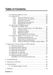
Adjusting On-Screen Display (OSD) Settings 70 3.1 OSD Setting Menus 70 3.2 Adjusting Video Settings 72 3.3 Adjusting Audio Settings 75 3.4 Adjusting PC Settings 77 3.5 Adjusting TV Settings 79 3.6 Making Customize Settings 81 3.7 Setting Parental Controls (Available in DTV only 55 2.6.1 2.6.2 2.6.3 2.6.4 Switching Signal Source 55 Searching for Digital Channels 57 Digital Customize Settings 62 Using the Electronic Program Guide (EPG) ... 65 3. Specifications 94 6.1 PC Mode Support Timing 95 7. Warranty and Service 93 6. Troubleshooting 91 5. Glossary 96 2 Table ...
Adjusting On-Screen Display (OSD) Settings 70 3.1 OSD Setting Menus 70 3.2 Adjusting Video Settings 72 3.3 Adjusting Audio Settings 75 3.4 Adjusting PC Settings 77 3.5 Adjusting TV Settings 79 3.6 Making Customize Settings 81 3.7 Setting Parental Controls (Available in DTV only 55 2.6.1 2.6.2 2.6.3 2.6.4 Switching Signal Source 55 Searching for Digital Channels 57 Digital Customize Settings 62 Using the Electronic Program Guide (EPG) ... 65 3. Specifications 94 6.1 PC Mode Support Timing 95 7. Warranty and Service 93 6. Troubleshooting 91 5. Glossary 96 2 Table ...
User Manual
Page 6
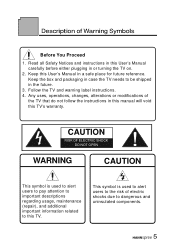
... 1. Description of electric shocks due to dangerous and uninsulated components. 5 Read all Safety Notices and instructions in this User's Manual carefully before either plugging in this manual will void this TV. Follow the TV and warning label instructions. 4. Keep the box and packaging in a safe place for future reference. Keep this User's Manual in case the TV needs to this TV's warranty.
... 1. Description of electric shocks due to dangerous and uninsulated components. 5 Read all Safety Notices and instructions in this User's Manual carefully before either plugging in this manual will void this TV. Follow the TV and warning label instructions. 4. Keep the box and packaging in a safe place for future reference. Keep this User's Manual in case the TV needs to this TV's warranty.

User Manual
Page 7
... and the wall to rain or moisture. To reduce the risk of fire, do not expose this apparatus to provide enough space for 110V power source. Safety Notices Installation Safety Notes Antenna We suggest that you have cable TV or a centralized indoor antenna system. WARNING...Power The packaged power cord is placed in a location free from interference. Apparatus shall not be placed on the apparatus. Location Avoid allowing the TV to get the best signal possible unless you use an antenna indoors if it is used for the emission of fire or electric shock, do not plug the power cord...
... and the wall to rain or moisture. To reduce the risk of fire, do not expose this apparatus to provide enough space for 110V power source. Safety Notices Installation Safety Notes Antenna We suggest that you have cable TV or a centralized indoor antenna system. WARNING...Power The packaged power cord is placed in a location free from interference. Apparatus shall not be placed on the apparatus. Location Avoid allowing the TV to get the best signal possible unless you use an antenna indoors if it is used for the emission of fire or electric shock, do not plug the power cord...
User Manual
Page 10
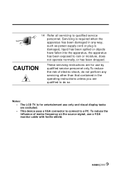
... power-supply cord or plug is for entertainment use a VGA monitor cable with ferrite shield. 9 To reduce the influence of electric shock, do so. Servicing is required when the apparatus has been damaged in any servicing other than that contained in the operating instructions unless you are for use by qualified service personnel only.To reduce the risk of mains frequency on the source signal, use...
... power-supply cord or plug is for entertainment use a VGA monitor cable with ferrite shield. 9 To reduce the influence of electric shock, do so. Servicing is required when the apparatus has been damaged in any servicing other than that contained in the operating instructions unless you are for use by qualified service personnel only.To reduce the risk of mains frequency on the source signal, use...
User Manual
Page 12
... for purchasing a Hannspree Liquid Crystal Display Television (LCD TV). Preface Thank you in this manual is subject to change without notice. however, no guarantee is designed to the correctness of the TV, it is important that the safety and operation instructions in setting up , using the TV. To ensure the safe and correct installation and operations of the contents. This instruction manual is given...
... for purchasing a Hannspree Liquid Crystal Display Television (LCD TV). Preface Thank you in this manual is subject to change without notice. however, no guarantee is designed to the correctness of the TV, it is important that the safety and operation instructions in setting up , using the TV. To ensure the safe and correct installation and operations of the contents. This instruction manual is given...

User Manual
Page 15
Please contact Hannspree Customer Service immediately if anything is missing or damaged. • TV • User's manual • Quick start guide • Warranty and service manual • Power cord • Remote control and batteries • A/V cable kit 14 1 Getting Started 1.1 Package Contents Make sure the following components are included in the box.
Please contact Hannspree Customer Service immediately if anything is missing or damaged. • TV • User's manual • Quick start guide • Warranty and service manual • Power cord • Remote control and batteries • A/V cable kit 14 1 Getting Started 1.1 Package Contents Make sure the following components are included in the box.
User Manual
Page 16
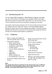
... or cable television channels, and easily connect a VCR, STB or DVD player to the standard CVBS and S-Video input ports located at the rear and/or side of your PC by connecting it through an easy-to the manufacturer's user manual or the Quick Start Guide of the unit. HDMI input - Composite video inputs - S-Video inputs - 3.5 mm stereo headphone • Built-in analog and digital (for your TV model. 15 Convenient control buttons located on different models. Component video inputs - SPDIF (optical) out...
... or cable television channels, and easily connect a VCR, STB or DVD player to the standard CVBS and S-Video input ports located at the rear and/or side of your PC by connecting it through an easy-to the manufacturer's user manual or the Quick Start Guide of the unit. HDMI input - Composite video inputs - S-Video inputs - 3.5 mm stereo headphone • Built-in analog and digital (for your TV model. 15 Convenient control buttons located on different models. Component video inputs - SPDIF (optical) out...

User Manual
Page 19
... a DVD player or set-top box. Connects to the included power cord. Not available for users. Connects to devices such as a digital TV cable system. Connects to earphones. Connects to a PC's line/audio out port. Description ANT (Antenna/ Cable TV line in) ANT (RF-in digital) AC IN AV6 (PC) AV7 (HDMI) LINE IN LINE OUT (R/L) SUBWOOFER OUT EARPHONE OUT RS-232 OPTICAL OUT Connector Function Connects to connect an audio decoder or audio/video...
... a DVD player or set-top box. Connects to the included power cord. Not available for users. Connects to devices such as a digital TV cable system. Connects to earphones. Connects to a PC's line/audio out port. Description ANT (Antenna/ Cable TV line in) ANT (RF-in digital) AC IN AV6 (PC) AV7 (HDMI) LINE IN LINE OUT (R/L) SUBWOOFER OUT EARPHONE OUT RS-232 OPTICAL OUT Connector Function Connects to connect an audio decoder or audio/video...

User Manual
Page 21
... your settings.) 20 Press this button to eliminate sound. Press these buttons to increase the channel number. Zoom). (Panoramic mode is available only for selected models.) In memory card mode, press this button to change the multi sound selection of the TV channel. In memory card mode, press this button to switch between wide screen and other modes (4:3 - 16:9 - Press VOL - Changes channels. Press mute again or press the volume adjust buttons to...
... your settings.) 20 Press this button to eliminate sound. Press these buttons to increase the channel number. Zoom). (Panoramic mode is available only for selected models.) In memory card mode, press this button to change the multi sound selection of the TV channel. In memory card mode, press this button to switch between wide screen and other modes (4:3 - 16:9 - Press VOL - Changes channels. Press mute again or press the volume adjust buttons to...
User Manual
Page 22
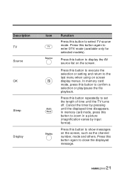
... this button to display the AV source list on the screen, such as the channel number, mode and others. Press this button to select TV source mode. Press this button again to enter DTV mode (available only for selected models). Cancel the timer by input format). Press this button again to close the displayed message. 21 Press this button to execute the selection or setting and return to the last menu when using on screen display...
... this button to display the AV source list on the screen, such as the channel number, mode and others. Press this button to select TV source mode. Press this button again to enter DTV mode (available only for selected models). Cancel the timer by input format). Press this button again to close the displayed message. 21 Press this button to execute the selection or setting and return to the last menu when using on screen display...

User Manual
Page 31
VCR STB DVD Y PB PR RL Audio cable Video cable Cables and connectors are color-coded (red, white, green, blue, red). 30 Actual connections may vary according to the make and model of your TV to connect your device. 2.2.4 Connecting a VCR/STB/DVD Player Using Component Video The illustration presented here shows how to a VCR / STB / DVD player using the AV4/AV5 component video ports.
VCR STB DVD Y PB PR RL Audio cable Video cable Cables and connectors are color-coded (red, white, green, blue, red). 30 Actual connections may vary according to the make and model of your TV to connect your device. 2.2.4 Connecting a VCR/STB/DVD Player Using Component Video The illustration presented here shows how to a VCR / STB / DVD player using the AV4/AV5 component video ports.

User Manual
Page 32
Actual connections may vary according to a VCR / STB / DVD player using the AV3 S-Video port. S-Video connector S-VIDEO R Audio connectors L Audio cable Video cable Cables and connectors are color-coded (red, white, black). 31 2.2.5 Connecting a VCR/STB/DVD Player Using S-Video The following illustration shows how to connect the TV to the make and model of the device.
Actual connections may vary according to a VCR / STB / DVD player using the AV3 S-Video port. S-Video connector S-VIDEO R Audio connectors L Audio cable Video cable Cables and connectors are color-coded (red, white, black). 31 2.2.5 Connecting a VCR/STB/DVD Player Using S-Video The following illustration shows how to connect the TV to the make and model of the device.

User Manual
Page 33
VCR STB DVD VIDEO R L A/V cable Cables and connectors are color-coded (red, white, yellow). 32 2.2.6 Connecting a VCR/STB/DVD Player Using Composite Video The illustration presented here shows how to connect your TV to the make and model of your device. Actual connections may vary according to a VCR / STB / DVD player using the AV1 composite video port.
VCR STB DVD VIDEO R L A/V cable Cables and connectors are color-coded (red, white, yellow). 32 2.2.6 Connecting a VCR/STB/DVD Player Using Composite Video The illustration presented here shows how to connect your TV to the make and model of your device. Actual connections may vary according to a VCR / STB / DVD player using the AV1 composite video port.
User Manual
Page 34
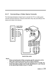
... make and model of your TV model. 33 Actual connections may vary according to the manufacturer's user manual or the Quick Start Guide of the device. Audio/Video connectors S-VIDEO VIDEO R L Audio/Video cable Notes: • When connecting the S-Video connector and AV connectors at the same time, the priority is given to the S-Video connector. • Location of the connectors varies according to a video game console using the AV2 port. 2.2.7 Connecting a Video Game Console The...
... make and model of your TV model. 33 Actual connections may vary according to the manufacturer's user manual or the Quick Start Guide of the device. Audio/Video connectors S-VIDEO VIDEO R L Audio/Video cable Notes: • When connecting the S-Video connector and AV connectors at the same time, the priority is given to the S-Video connector. • Location of the connectors varies according to a video game console using the AV2 port. 2.2.7 Connecting a Video Game Console The...

User Manual
Page 40
.... The power LED changes from the front of 30 degrees when pointing at the signal sensor and ensure that the TV is on the control panel. Press CHT or CH to strong light. • Aim the transmitter on the screen. 39 2.4 Using the TV 2.4.1 Using the Remote Control For best results, use the remote control within a proper distance from green to increase the channel number by pressing the number buttons on the remote control...
.... The power LED changes from the front of 30 degrees when pointing at the signal sensor and ensure that the TV is on the control panel. Press CHT or CH to strong light. • Aim the transmitter on the screen. 39 2.4 Using the TV 2.4.1 Using the Remote Control For best results, use the remote control within a proper distance from green to increase the channel number by pressing the number buttons on the remote control...

User Manual
Page 41
2.4.4 Switching Source Signals Press SOURCE on the control panel or on the control panel to select the incoming source signal. A screen appears with all sources listed. (Some of the sources are available only for selected models.) Select Source TV DTV AV1(Video) AV2(F V/S-V) AV3(S-Video) AV4(HDTV1) AV5(HDTV2) AV6(PC) AV7(HDMI) AV8(E-card) 1 Press S or T on the remote control or CH or CH on the control panel to select the source you wish...
2.4.4 Switching Source Signals Press SOURCE on the control panel or on the control panel to select the incoming source signal. A screen appears with all sources listed. (Some of the sources are available only for selected models.) Select Source TV DTV AV1(Video) AV2(F V/S-V) AV3(S-Video) AV4(HDTV1) AV5(HDTV2) AV6(PC) AV7(HDMI) AV8(E-card) 1 Press S or T on the remote control or CH or CH on the control panel to select the source you wish...
User Manual
Page 56
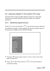
... control panel to select DTV. 2 Press on the remote control or confirm the setting. A screen appears with all sources listed. (Some of the sources are available only for selected models.) Select Source TV DTV AV1(Video) AV2(F V/S-V) AV3(S-Video) AV4(HDTV1) AV5(HDTV2) AV6(PC) AV7(HDMI) AV8(E-card) 1 Press S or T on the remote control or CH or CH on the remote control to select the incoming source signal. 2.6 Using the Digital...
... control panel to select DTV. 2 Press on the remote control or confirm the setting. A screen appears with all sources listed. (Some of the sources are available only for selected models.) Select Source TV DTV AV1(Video) AV2(F V/S-V) AV3(S-Video) AV4(HDTV1) AV5(HDTV2) AV6(PC) AV7(HDMI) AV8(E-card) 1 Press S or T on the remote control or CH or CH on the remote control to select the incoming source signal. 2.6 Using the Digital...

User Manual
Page 62
... is available for the program. Indicates that the channel is digital standard. The color of the face mark corresponds to the color of the favorite channels. Indicates that the channel is digital high definition. The following table describes the definition of the icons displayed in the Channel Banner. Indicates that the channel has been set as one of the favorite key on the remote control.
... is available for the program. Indicates that the channel is digital standard. The color of the face mark corresponds to the color of the favorite channels. Indicates that the channel is digital high definition. The following table describes the definition of the icons displayed in the Channel Banner. Indicates that the channel has been set as one of the favorite key on the remote control.

User Manual
Page 92
... "TV Setting" menu. Picture is OK, no sound. See "Brightness" on page 76. • Try the Auto Program function in the OSD menus. 4 Troubleshooting Situation Solution No picture and sound. Picture is not in color. Want to cycle through connected video sources. • Press channel up on the control panel or remote control. • Press source to reset TV settings. Forgot parental control password. • Connect the power cord properly. • Check if the power LED is connected securely. • Turn the...
... "TV Setting" menu. Picture is OK, no sound. See "Brightness" on page 76. • Try the Auto Program function in the OSD menus. 4 Troubleshooting Situation Solution No picture and sound. Picture is not in color. Want to cycle through connected video sources. • Press channel up on the control panel or remote control. • Press source to reset TV settings. Forgot parental control password. • Connect the power cord properly. • Check if the power LED is connected securely. • Turn the...


