Energy Guide
Page 1
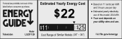
$22 Haier L32D1120 $11 $25 (30" - 34") use of this model: 204 kWh
$22 Haier L32D1120 $11 $25 (30" - 34") use of this model: 204 kWh
User Manual
Page 2
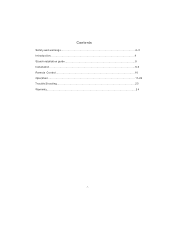
Contents Safety and warnings 2-3 Introduction 4 Stand installation guide 5 Installation...6-9 Remote Control 10 Operation...11-22 Trouble Shooting 23 Warranty...2 4 -1-
Contents Safety and warnings 2-3 Introduction 4 Stand installation guide 5 Installation...6-9 Remote Control 10 Operation...11-22 Trouble Shooting 23 Warranty...2 4 -1-
User Manual
Page 3
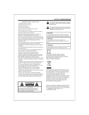
... the like. power-supply cord or plug is damaged, liquid has been spilled or objects have fallen into your used as the disconnect device, the disconnect device shall remain readily operable. 15) The ventilation should be exposed to qualified service personnel. CAUTION TO REDUCE THE RISK OF ELECTRIC SHOCK, DO NOT REMOVE COVER (OR BACK).NO USER SERVICEABLE PARTS INSIDE. Please...
... the like. power-supply cord or plug is damaged, liquid has been spilled or objects have fallen into your used as the disconnect device, the disconnect device shall remain readily operable. 15) The ventilation should be exposed to qualified service personnel. CAUTION TO REDUCE THE RISK OF ELECTRIC SHOCK, DO NOT REMOVE COVER (OR BACK).NO USER SERVICEABLE PARTS INSIDE. Please...
User Manual
Page 4
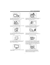
... naked flame sources, such as lighted candles on , or suddenly push the television or its stand. Do not open the cabinet. Never stand on, lean on or near the television. Adequate ventilation is essential to disconnect the AC power cord from the AC outlet. Never spill any kind of electrical components. When the television receiver is not used in the operation of heat...
... naked flame sources, such as lighted candles on , or suddenly push the television or its stand. Do not open the cabinet. Never stand on, lean on or near the television. Adequate ventilation is essential to disconnect the AC power cord from the AC outlet. Never spill any kind of electrical components. When the television receiver is not used in the operation of heat...
User Manual
Page 5
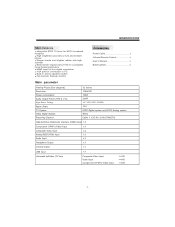
...Remote Control 1 User s Manual 1 Battery(AAA 2 Main parameter Viewing Picture Size (diagonal) Resolution: 32 inches 1366x768 Power consumption: Audio Output Power (THD Input Power Voltage: 7%): 135W 2x8W AC 100V-240V 50/60Hz Aspect Ratio: 16:9 TV System: Video Signal System: ATSC Digital system and NTSC Analog system NTSC Receiving Channel: Cable :1-135/ Air: 2-69 (ATV&DTV) High-Definition Multimedia Interface (HDMI) Input x 2 Component (YPbPr) Video Input x1 Composite Video Input x2 Analog RGB (VGA) Input x1 Audio Input x3 Headphone Output x1 Coaxial Output x1 USB...
...Remote Control 1 User s Manual 1 Battery(AAA 2 Main parameter Viewing Picture Size (diagonal) Resolution: 32 inches 1366x768 Power consumption: Audio Output Power (THD Input Power Voltage: 7%): 135W 2x8W AC 100V-240V 50/60Hz Aspect Ratio: 16:9 TV System: Video Signal System: ATSC Digital system and NTSC Analog system NTSC Receiving Channel: Cable :1-135/ Air: 2-69 (ATV&DTV) High-Definition Multimedia Interface (HDMI) Input x 2 Component (YPbPr) Video Input x1 Composite Video Input x2 Analog RGB (VGA) Input x1 Audio Input x3 Headphone Output x1 Coaxial Output x1 USB...
User Manual
Page 6
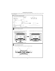
... Stand to help you easily install the stand. Place the Stand on a soft and flat surface (blanket, foam, cloth, etc.) to prevent any damage to the TV. 2. STAND INSTALLATION GUIDE This STAND INSTALLATION GUIDE is provided to the TV by using the 4 supplied screws. 1 2 3 4 -5- Please carefully follow Steps 1 through 3. Place the TV face down on the TV as shown below. Open the box and find the parts...
... Stand to help you easily install the stand. Place the Stand on a soft and flat surface (blanket, foam, cloth, etc.) to prevent any damage to the TV. 2. STAND INSTALLATION GUIDE This STAND INSTALLATION GUIDE is provided to the TV by using the 4 supplied screws. 1 2 3 4 -5- Please carefully follow Steps 1 through 3. Place the TV face down on the TV as shown below. Open the box and find the parts...
User Manual
Page 7
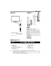
... Port (PC Input) Pr COMPONENT Pb INPUT AUDIO L INPUT AV1 Y R 345 VGA INPUT HEADPHONE PC AUDIO COAXIAL INPUT RF INPUT 6 7 8 9 10 7. Antenna Socket 11. AC Power Socket Note: 1. In MENU mode, press "CH+" or "CH-" to select items in standby mode, press "CH+" or "CH-" to change the channel up and down. Headphone Output 8. Front panel Side panel INSTALLATION 3 1 2 R 9 L 8 Video 7 AV2 6 USB SOURCE 1 MENU 2 CH+ 3 CH- STANDBY. REAR AV INPUT/OUTPUT 1. STANDBY: Press this button to turn on the TV. 4. STANDBY 5 30 30 1: Remote control sensor. 2: Indicator LED: GREEN...
... Port (PC Input) Pr COMPONENT Pb INPUT AUDIO L INPUT AV1 Y R 345 VGA INPUT HEADPHONE PC AUDIO COAXIAL INPUT RF INPUT 6 7 8 9 10 7. Antenna Socket 11. AC Power Socket Note: 1. In MENU mode, press "CH+" or "CH-" to select items in standby mode, press "CH+" or "CH-" to change the channel up and down. Headphone Output 8. Front panel Side panel INSTALLATION 3 1 2 R 9 L 8 Video 7 AV2 6 USB SOURCE 1 MENU 2 CH+ 3 CH- STANDBY. REAR AV INPUT/OUTPUT 1. STANDBY: Press this button to turn on the TV. 4. STANDBY 5 30 30 1: Remote control sensor. 2: Indicator LED: GREEN...
User Manual
Page 8
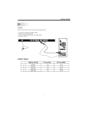
Connect a VGA and audio cable. 2. Turn on the TV and switch to VGA mode. 4. Connect the power cord. 3. Turn on the PC. PC STEPS: Be sure both the TV and computer are powered off. 1. AC INPUT 100-240V~50/60Hz HDMI 1 HDMI 2 Pr COMPONENT Pb INPUT AUDIO L INPUT AV1 Y R VGA INPUT HEADPHONE PC AUDIO COAXIAL INPUT RF INPUT INSTALLATION PRESET MODE RESOLUTION 1 640*480 2 800*600 3 1024*768 4 1280*1024 V.Freq.(Hz) 60 60 60 60 H.Freq.(KHz) 31.47 37.88 48.36 63.98 -7-
Connect a VGA and audio cable. 2. Turn on the TV and switch to VGA mode. 4. Connect the power cord. 3. Turn on the PC. PC STEPS: Be sure both the TV and computer are powered off. 1. AC INPUT 100-240V~50/60Hz HDMI 1 HDMI 2 Pr COMPONENT Pb INPUT AUDIO L INPUT AV1 Y R VGA INPUT HEADPHONE PC AUDIO COAXIAL INPUT RF INPUT INSTALLATION PRESET MODE RESOLUTION 1 640*480 2 800*600 3 1024*768 4 1280*1024 V.Freq.(Hz) 60 60 60 60 H.Freq.(KHz) 31.47 37.88 48.36 63.98 -7-

User Manual
Page 9
Input impendance:75 unbalanced. -8- ANTENNA INSTALLATION Note: Aerial connections:IEC(female).
Input impendance:75 unbalanced. -8- ANTENNA INSTALLATION Note: Aerial connections:IEC(female).

User Manual
Page 10
... (video) W White(audio L) R Red(audio R or Pr) B Blue(Pb) G Green(Y) AC INPUT 100-240V~50/60Hz HDMI 1 G B R W R HDMI 2 Pr COMPONENT Pb INPUT AUDIO L INPUT AV1 Y R VGA INPUT W R HEADPHONE PC AUDIO COAXIAL INPUT RF INPUT HDMI VIDEO EQUIPMENT W R TO VIDEO output To audio outputs R L Video AV2 USB The television's inputs can connect a Blu-ray player, DVD player, or other video equipment to these ports. Please see the diagram below. You can use this AV input to conveniently connect devices that you may also need to refer to the owner's manual of...
... (video) W White(audio L) R Red(audio R or Pr) B Blue(Pb) G Green(Y) AC INPUT 100-240V~50/60Hz HDMI 1 G B R W R HDMI 2 Pr COMPONENT Pb INPUT AUDIO L INPUT AV1 Y R VGA INPUT W R HEADPHONE PC AUDIO COAXIAL INPUT RF INPUT HDMI VIDEO EQUIPMENT W R TO VIDEO output To audio outputs R L Video AV2 USB The television's inputs can connect a Blu-ray player, DVD player, or other video equipment to these ports. Please see the diagram below. You can use this AV input to conveniently connect devices that you may also need to refer to the owner's manual of...
User Manual
Page 11
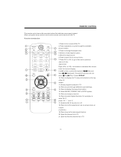
... / Forward (The buttons do not work.) Stop Play / Pause REPEAT. 10.Press to display the TV status information on the top of the TV screen. 11.Shows program schedule in TV. 12.Press to cycle through the available picture modes. 3.Press to change a channel. 16.Press to the next or previous channel in TV. -10- REMOTE CONTROL The remote control cannot be operated unless the batteries...
... / Forward (The buttons do not work.) Stop Play / Pause REPEAT. 10.Press to display the TV status information on the top of the TV screen. 11.Shows program schedule in TV. 12.Press to cycle through the available picture modes. 3.Press to change a channel. 16.Press to the next or previous channel in TV. -10- REMOTE CONTROL The remote control cannot be operated unless the batteries...
User Manual
Page 24
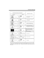
... red, green, blue, black or white. TROUBLE SHOOTING Trouble phenomenon Symptom Picture Audio Snow Noise Inspection Check antenna position, direction or connection Ghost antenna position, direction Normal audio or connection Interference Normal Picture No picture No color Noise electronic equipment,car/ motorcycle,fluorescent light Mute Volume (check if mute is activated or if the audio system connections are not correct) Mute Power cord is not inserted Power switch is not opened Contrast and brightness/volume setup...
... red, green, blue, black or white. TROUBLE SHOOTING Trouble phenomenon Symptom Picture Audio Snow Noise Inspection Check antenna position, direction or connection Ghost antenna position, direction Normal audio or connection Interference Normal Picture No picture No color Noise electronic equipment,car/ motorcycle,fluorescent light Mute Volume (check if mute is activated or if the audio system connections are not correct) Mute Power cord is not inserted Power switch is not opened Contrast and brightness/volume setup...


